Table of Contents
Advertisement
Quick Links
CHAPTER 1
Chapter 1
INTRODUCTION
The MS-6182 ATX WH8 mainboard is a high-performance
computer mainboard based on Intel
®
for the Intel
Pentium
business/personal desktop markets.
The Intel
chipset for the Intel
accelerator architecture consists of dedicated multi-media engines executing
in parallel to deliver high performance 3D, 2D, and motion compensation
video capabilities. An integrated centralized memory arbiter allocates
memory bandwidth to multiple system agents to optimize system memory
utilization. A new chipset component interconnect, the hub interface, is
designed into the Intel
channel between the memory controller hub and I/O hub controller.
The Intel
Graphics and Memory Controller Hub (GMCH), the I/O Controller Hub
(ICHO/ICH) and the Firmware Hub (FWH). The GMCH integrates a 66/
100MHz, P6 family system bus controller, 2D/3D graphics accelerator,
100MHz SDRAM controller and high-speed hub interface for communication
with the ICHO/ICH. The ICHO/ICH integrates an Ultra ATA/33(ICHO) or
Ultra ATA/66(ICH) controller, USB host controller, LPC interface controller,
FWH interface conroller, PCI interface controller, AC'97 digital controller and
a hub interface for communication with the GMCH.
The Intel
®
Intel
810 chipset. The FWH is key to enabling future security and
manageability infrastructure for the PC platform.
®
®
II/III or Celeron
®
810 chipset is the first generation Integrated Graphics
®
®
Pentium
II/III Celeron
®
810 chipset to provide an efficient communication
®
810 chipset contains three core components: the
®
82802 Firmware Hub (FWH) component is part of the
810 chipset. The MS-6182 is designed
TM
processor for inexpensive
TM
processor. The graphics
1-1
INTRODUCTION
Advertisement
Table of Contents

Related Manuals for MSI MS-6182


Summary of Contents for MSI MS-6182
- Page 1 CHAPTER 1 INTRODUCTION Chapter 1 INTRODUCTION The MS-6182 ATX WH8 mainboard is a high-performance ® computer mainboard based on Intel 810 chipset. The MS-6182 is designed ® ® for the Intel Pentium II/III or Celeron processor for inexpensive business/personal desktop markets.
-
Page 2: Mainboard Features
CHAPTER 1 INTRODUCTION 1.1 Mainboard Features l Slot 1 for Intel ® ® ® Pentium II/Pentium III/Celeron processor. l Supports 233MHz, 266MHz, 300MHz, 333MHz, 350MHz, 400MHz, 450MHz, 500MHz and faster processor. Chipset l Intel ® 810 (GMCH) chipset. (421 BGA) - Integrated Graphics Controller - Intel DDM Architecture - SDRAM memory Independent of System Bus... - Page 3 CHAPTER 1 INTRODUCTION On-Board IDE l An IDE controller on the ICH chipset provides IDE HDD/CD-ROM with PIO, Bus Master and Ultra DMA/66 operation modes. l Can connect up to four IDE devices. On-Board Peripherals l On-Board Peripherals include: - 1 floppy port supports 2 FDD with 360K, 720K, 1.2M, 1.44M and 2.88Mbytes.
- Page 4 CHAPTER 1 INTRODUCTION Dimension l ATX Form Factor: 30.5(L)x19.2(W)x4 layers PCB Mounting l 8 mounting holes. System Hardware Monitor l CPU/Power Supply/Chassis Fan Revolution Detect l CPU Fan Control (the fan will automatically stop when the system enters suspend mode) l System Voltage Detect l CPU Overheat Warning.
-
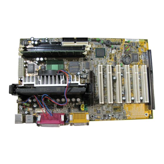
Page 5: Mainboard Layout
MDM_IN USB2 PCI SLOT 1 JGS1 Intel ® ICH0/ICH PCI SLOT 2 Creative JMDM1 SYSFAN JGL1 ES1373 PCI SLOT 3 JWOL1 JFP1 JBAT1 PCI SLOT 4 BATT PCI SLOT 5 W83628F PCI SLOT 6 ISA SLOT MS-6182 ATX WH8 Mainboard... -
Page 6: Hardware Installation
Chapter 2 HARDWARE INSTALLATION 2.1 Central Processing Unit: CPU 2.1-1 Processor Installation Procedure Step 1: Install the Retention Mechanism. Attach the Retention Mechanism to the Mainboard. Push the Plastic lock to secure the Retention Mechanism into the mainboard. Secure the processor by pulling up the Retention Insert the processor Mechanism Processor... -
Page 7: Cpu Core Speed Derivation Procedure
2.1-2 CPU Core Speed Derivation Procedure The mainboard CPU Bus Frequency can be set through BIOS setup CPU Clock 66MHz Core/Bus ratio then CPU core speed Host Clock x Core/Bus ratio 66MHz x 3.5 233MHz 2.1-3 Overclocking Jumper: J2 Overclocking is operating a CPU/Processor beyond its specified frequency. - Page 8 2.1-4 Fan Power Connector: CPUFAN/PSFAN/SYSFAN These connectors support system cooling fan with + 12V. It supports three pin head connector. When connecting the wire to the connector, always take note that the red wire is the positive and should be connected to the +12V, the black wire is Ground and should be connected to GND.
- Page 9 A battery must be used to retain the mainboard configuration in CMOS RAM. Short 1-2 pins of JBAT1 to store the CMOS data. JBAT1 Clear Data Keep Data Note: You can clear CMOS by shorting 2-3 pin, while the system is off. Then, return to 1-2 pin position.
-
Page 10: Memory Bank Configuration
2.3-1 Memory Bank Configuration The mainboard supports a maximum memory size of 256MB(64-bit technol- ogy) or 512MB(128-bit technology for SDRAM: It provides three 168-pin unbuffered DIMMs (Double In-Line Memory Module) sockets. It supports 8 MB to 128 Mbytes DIMM memory module. NOTE: When you install Double Bank DIMM or DIMM 2, DIMM 3 will not be functional and vice versa. -
Page 11: Memory Installation Procedures
2.3-2 Memory Installation Procedures A. How to install a DIMM Module Single Sided DIMM Double Sided DIMM 1. The DIMM slot has 2 Notch Keys “VOLT and DRAM”, so the DIMM memory module can only fit in one direction. 2. Insert the DIMM memory module vertically into the DIMM slot. Then push it in. -
Page 12: Memory Population Rules
2.3-3 Memory Population Rules 1. Supports only SDRAM DIMM. 2. To operate properly, at least one 168-pin DIMM module must be in- stalled. 3. This mainboard supports Table Free memory, so memory can be installed on DIMM1, DIMM 2 or DIMM 3 in any order. 4. -
Page 13: Case Connector: Jfp1
2.4 Case Connector: JFP1 The Keylock, Power Switch, Reset Switch, Power LED, Speaker, and HDD LED are all connected to the JFP1 connector block. Reset Switch Power Switch Single Dual Speaker Color Color Power LED Buzzer (short pin) Keylock JFP1... - Page 14 2.4-1 Power Switch Connect to a 2-pin push button switch. This switch has the same feature with JRMS1. 2.4-2 Reset Switch Reset switch is used to reboot the system rather than turning the power ON/ OFF. Avoid rebooting while the HDD LED is lit. You can connect the Reset switch from the system case to this pin.
-
Page 15: Floppy Disk Connector: Fdd
2.5 Floppy Disk Connector: FDD The mainboard also provides a standard floppy disk connector FDD that supports 360K, 720K, 1.2M, 1.44M and 2.88M floppy disk types. This connector supports the provided floppy drive ribbon cables. 2-10... -
Page 16: Hard Disk Connectors: Ide1 & Ide2
2.6 Hard Disk Connectors: IDE1 & IDE2 The mainboard has a 32-bit Enhanced PCI IDE and Ultra DMA/66 (ICH)/ Ultra DMA/33(ICH0) Controller that provides PIO mode 0~4, Bus Master, and Ultra DMA/33 function. It has two HDD connectors IDE1 (primary) and IDE2 (secondary). -
Page 17: Atx 20-Pin Power Connector: Jpwr1
2.7-1 ATX 20-pin Power Connector: JPWR1 This connector supports the power button on-board. Using the ATX power supply, functions such as Modem Ring Wake-Up and Soft Power Off are supported by this mainboard. This power connector supports instant power on function which means that system will boot up instantly when the power connector is inserted on the board. -
Page 18: Irda Infrared Module Connector: Ir
2.8 IrDA Infrared Module Connector: IR The mainboard provides one 5-pin infrared (IR) connector for IR modules. This connector is for optional wireless transmitting and receiving infrared module. You must configure the setting through the BIOS setup to use the IR function. - Page 19 The mainboard has a 9-pin male DIN connector for serial port COM A. This port is a 16550A high speed communication port that send/receive 16 bytes FIFOs. You can attach a mouse or a modem cable directly into this connec- tor.
- Page 20 The mainboard provides a 25 pin female centronic connector for LPT. A parallel port is a standard printer port that also supports Enhanced Parallel Port(EPP) and Extended capabilities Parallel Port(ECP). See connector and pin definition below: Parallel Port (25-pin Female) LPT 1 PIN DEFINITION SIGNAL...
-
Page 21: Keyboard Connector: Jkbms1
® The mainboard provides a standard PS/2 mouse mini DIN connector for ® ® attaching a PS/2 mouse. You can plug a PS/2 mouse directly into this connector. The connector location and pin definition are shown below: Pin5 Mouse Clock Pin6 Pin3 Pin4... -
Page 22: Joystick/Midi Connectors
2.13 Joystick/Midi Connectors You can connect joystick or game pad to this connector. Joystick/MIDI 2.14 Audio Port Connectors Line Out is a connector for Speakers or Headphones. Line In is used for external CD player, Tape layer, or other audio devices. Mic is a connector for the microphones. -
Page 23: Usb Connectors
2.15 USB Connectors The mainboard provides a UHCI(Universal Host Controller Interface) Universal Serial Bus root for attaching USB devices like: keyboard, mouse and other USB devices. You can plug the USB device directly to this connector. USB Port 2 1 2 3 4 USB Port 1 SIGNAL -Data0... - Page 24 Attach a power saving switch to JGS1. When the switch is pressed, the system immediately goes into suspend mode. Press any key and the system wakes up. JGS1 2-19...
- Page 25 JGL1 can be connected with a LED. When the 2-pin LED is connected to JGL1, the light will turn green, when system is On. During sleep mode, the 2-pin LED will change color from Green to Orange. JGL1 2-20...
- Page 26 The JWOL1 connector is for use with LAN add-on cards that supports Wake Up on LAN function. To use this function, you need to set the “Wake-Up on LAN” to enable at the BIOS Power Management Setup. JWOL1 SIGNAL 5VSB MP_WAKEUP Note: LAN wake-up signal is active “high”.
- Page 27 The JMDM1 connector is for used with Modem add-on card that supports the Modem Wake Up function. JMDM1 SIGNAL MDM_WAKEUP 5VSB Note: Modem wake-up signal is active “low”. Note: To be able to use this function, you need a power supply that provide enough power for this feature.
- Page 28 2.20 Modem-In: MDM_IN The connector is for Modem with internal voice connector. SPK IN GND MIC OUT Modem_In SPK_IN is connected to the Modem Speaker Out connector. MIC_OUT is connected to the Modem Microphone In connector. 2-23...
- Page 29 This connector is used for DVD Add on Card with Line In connector. LGND R AUX_IN 2-24...
- Page 30 This connector is for CD-ROM audio connector. LGND R CD_In 2-25...
- Page 31 The JKBV1 jumper is for setting keyboard power. This function should be set in the BIOS for the keyboard Wake-up function. JKBV1 5V (default) 5V Standby Disable keyboard Enable keyboard power on function power on function Note: To be able to use this function, you need a power supply that provide enough power for this feature.
- Page 32 This connector is connected to a 2-pin connector chassis switch. If the Chassis is open, the switch will be open. The system will record this status. To clear the warning, you must enter the BIOS settting and clear the status. 2-27...
- Page 33 This jumper is used to lock/unlock BIOS Flash. This Jumper should be unlock when flashing/programming the BIOS. BIOS Flash BIOS Flash Unlocked Locked 2-28...
- Page 34 This jumper will enable the case speaker/buzzer to be transferred to the Audio speaker. Enabled Disabled 2-29...
- Page 35 The mainboard provides a front Universal Serial Bus connector. This is an optional USB connector for Front Panel. USB Front Connector 2-30...
- Page 36 This jumper is used to Enabled or Disabled the USB Front Connector. If the USB Front connector is set to enabled, the top USB port at the rear I/O panel will be disabled. If the USB Front connector is set to disabled, the USB port at rear I/O panel will both be operational.
- Page 37 J16 is an optional Front Panel Connector. IR_P IRTX IRRX FPSLP FP_Reset FPBUT_IN HDR_Blink_Yel HDR_Blink_Grn HD_PWR 2-32...
- Page 38 The mainboard provides a Special Diagnostic LED for users to be aware of their mainboard conditions. The LED helps user determine the problem of the mainboard. Diagnostic LED 2-33...
- Page 39 Diagnostic LED Function Diagnostic LED Possible Problem/ Description Solution System D-LED will hang here System Power ON. The Processor might be damage or This will start BIOS Initialization not installed properly Damage/Discharge Lithium Battery Early Chipset Initialization System D-LED will hang here Memory Detection Test The Memory module might be Testing Onboard memory size...
- Page 40 This is used to check the AGP card or BX chipset temperature. The J3 is a 2-pin connector which can be inserted with a 20cm length thermistor. It is located near the chipset heatsink that monitors the chipset temperature. The BIOS setup for “TOP TECH.
- Page 41 The Audio/Modem Riser specification is an open industry-standard specification that defines a hardware scalable Original Equipmet Manufacturer (OEM) mainboard riser board and interface, which supports both audio and modem. 2-36...
- Page 42 The Panel link/TV-Out Interface (PTI) is a MSI in-house designed which supportd either Panel link or TV-out function. To be able utilize both AMR and PTI simultaneously you need to use MSI product like MS-5965 & MS- 5966 or MS-5964 & MS-5966.
-
Page 43: Award Bios Setup
® Chapter 3 AWARD BIOS SETUP ® Award BIOS ROM has a built-in Setup program that allows users to modify the basic system configuration. This type of information is stored in battery-backed RAM (CMOS RAM), so that it retains the Setup information when the power is turned off. -
Page 44: Status Page Setup Menu/Option Page Setup Menu
® Power on the computer and press <Del> immediately to allow you to enter Setup. The other way to enter Setup is to power on the computer. When the below message appears briefly at the bottom of the screen during the POST (Power On Self Test), press <Del>... -
Page 45: Standard Cmos Setup
® ® Once you enter Award BIOS CMOS Setup Utility, the Main Menu (Figure 1) will appear on the screen. The Main Menu allows you to select from twelve setup functions and two exit choices. Use arrow keys to select among the items and press <Enter>... - Page 46 ® Advanced Chipset Features Use this menu to change the values in the chipset registers and optimize your system’s performance. Integrated Peripherals Use this menu to specify your settings for integrated peripherals. Power Management Setup Use this menu to specify your settings for power management. PnP/PCI Configuration This entry appears if your system supports PnP/PCI.
- Page 47 ® The items in Standard CMOS Setup Menu are divided into 10 catego- ries. Each category includes no, one or more than one setup items. Use the arrow keys to highlight the item and then use the <PgUp> or <PgDn> keys to select the value you want in each item.
- Page 48 ® Date The date format is <day><month> <date> <year>. Day of the week, from Sun to Sat, determined by BIOS. Read-only. month The month from Jan. through Dec. date The date from 1 to 31 can be keyed by numeric function keys.
- Page 49 ® If the controller of HDD interface is SCSI, the selection shall be “None”. If the controller of HDD interface is CD-ROM, the selection shall be “None”. Access Mode The settings are Auto, Normal, Large,LBA. Cylinder number of cylinders Head number of heads Precomp write precom...
-
Page 50: Anti-Virus Protection
® CMOS Setup Utility - Copyright(C) 1984-1999 Award Software Advanced BIOS Features Anti-Virus Protection Disabled CPU Internal Cache Enabled Item Help External Cache Enabled CPU L2 Cache ECC Checking Enabled Processor Number Feature Enabled Menu Level > Quick Power On Self Test Disabled First Boot device Floppy... - Page 51 ® CPU Internal Cache The default value is Enabled. Enabled (default) Enable cache Disabled Disable cache Note: The internal cache is built in the processor. External Cache Choose Enabled or Disabled. This option enables the level 2 cache memory. CPU L2 Cache ECC Checking Choose Enabled or Disabled.
- Page 52 ® Swap Floppy Drive Switches the floppy disk drives between being designated as A and B. Default is Disabled. Boot Up Floppy Seek During POST, BIOS will determine if the floppy disk drive installed is 40 or 80 tracks. 360K type is 40 tracks while 760K, 1.2M and 1.44M are all 80 tracks.
-
Page 53: Security Option
® Security Option This category allows you to limit access to the system and Setup, or just to Setup. System The system will not boot and access to Setup will be denied if the correct password is not entered at the prompt. Setup(default) The system will boot, but access to Setup will be denied if the correct password is not entered at the prompt. - Page 54 ® The Advanced Chipset Features Setup option is used to change the values of the chipset registers. These registers control most of the system options in the computer. Choose the “ADVANCED CHIPSET FEATURES” from the Main Menu and the following screen will appear. CMOS Setup Utility - Copyright(C) 1984-1999 Award Software Advanced Chipset Features SDRAM CAS Latency Time...
- Page 55 ® SDRAM CAS latency Time When synchronous DRAM is installed, the number of clock cycles of CAS latency depends on the DRAM timing. The settings are: 2 and 3. SDRAM Cycle Time Tras/Trc Select the number of SCLKs for an access cycle. The settings are: 5/7 and 6/8.
- Page 56 ® Video BIOS Cacheable Select Enabled allows caching of the video BIOS , resulting in better system performance. However, if any program writes to this memory area, a system error may result. The settings are: Enabled and Disabled. Memory Hole At 15M-16M You can reserve this area of system memory for ISA adapter ROM.
-
Page 57: Onchip Primary/Secondary Pci Ide
® CMOS Setup Utility - Copyright(C) 1984-1999 Award Software Integrated Peripherals OnChip Primary PCI IDE Enabled OnChip Secondary PCI IDE Enabled Item Help IDE Primary Master PIO Auto IDE Primary Slave PIO Auto IDE Secondary Master PIO Auto Menu Level >... - Page 58 ® IDE Primary/Secondary Master/Slave PIO The four IDE PIO (Programmed Input/Output) fields let you set a PIO mode (0-4) for each of the four IDE devices that the onboard IDE interface supports. Modes 0 through 4 provide successively increased performance. In Auto mode, the system automatically determines the best mode for each device.
-
Page 59: Ide Hdd Block Mode
® Init Display First PCI Slot If both PCI VGA card and AGP card are installed, the system will display the PCI VGA card first. If both PCI VGA card and AGP card are installed, the system will show the AGP card first. -
Page 60: Uart Mode Select
® UART Mode Select This item allows you to determine which InfraRed(IR) function of the onboard I/O chip, this functions uses. Onboard Parallel Port Disabled There is a built-in parallel port on the (3BCH/IRQ7)/ on-board Super I/O chipset that pro- (278H/IRQ5)/ vides Standard, ECP, and EPP features. -
Page 61: Pwron After Pwr-Fail
® channels 3 or 1. The onboard parallel port is EPP Spec. compliant, so after the user chooses the onboard parallel port with the EPP function, the following message will be displayed on the screen: “EPP Mode Select.” At this time either EPP 1.7 spec. -
Page 62: Acpi Function
® The Power Management Setup allows you to configure you system to most effectively save energy while operating in a manner consistent with your own style of computer use. CMOS Setup Utility - Copyright(C) 1984-1999 Award Software Power Management Setup ACPI Function Enabled ACPI Suspend Type... -
Page 63: Acpi Suspend Type
® ACPI Suspend Type This item will set which ACPI suspend type will be used. Power Management This category allows you to select the type (or degree) of power saving and is directly related to the following modes: Suspend Mode HDD Power Down There are three selections for Power Management, two of which have fixed mode settings. -
Page 64: Soft-Off By Pwrbtn
® Video Off In Suspend This determines the manner in which the monitor is blanked. The settings are: Yes and No. Suspend Type Select the Suspend Type. The settings are: PWRON Suspend, Stop Grant. Modem Use IRQ This determines the IRQ in which the MODEM can use. The settings are: 3, 4, 5, 7, 9, 10, 11, NA. -
Page 65: Wake-Up On Lan
® Wake-Up on LAN To use this function, you need a LAN add-on card which support power on functions. It should also support the wake-up on LAN jumper (JWOL1). Enabled Wake up on LAN supported. Disabled Wake up on LAN not supported. CPU Thermal-Throttling Select the CPU THRM-Throttling rate. -
Page 66: Reset Configuration Data
® This section describes configuring the PCI bus system. PCI, or Personal Computer Interconnect, is a system which allows I/O devices to operate at speeds nearing the speed the CPU itself uses when communicating with its own special components. This section covers some very technical items and it is strongly recommended that only experienced users should make any changes to the default settings. - Page 67 ® Resource Controlled By The Award Plug and Play BIOS has the capacity to automatically configure all of the boot and Plug and Play compatible devices. However, this capability means absolutely nothing unless you are using a Plug and ® Play operating system such as Windows 95/98.
-
Page 68: Cpu Warning Temperature
® This section shows the Status of you CPU, Fan, Warning for overall system status. CMOS Setup Utility - Copyright(C) 1984-1999 Award Software PC Health Status CPU Warning Temperature Disabled Current System Temp C/100 Item Help Current CPU1 Temperature C/156 Current CPUFAN1 Speed 0 RPM Current CPUFAN2 Speed... - Page 69 ® Current System Temp/Current CPU1 Temperature/Current CPUFAN1/CPUFAN2/CPUFAN3 Speed/IN0/1/3/+5V/+12V/- 12V/-5V/VBAT(V)/5VSB(V) This will show the CPU/FAN/System voltage chart and FAN Speed. 3-27...
-
Page 70: Auto Detect Dimm/Pci Clk
® This section is for setting CPU Frequency/Voltage Control. CMOS Setup Utility - Copyright(C) 1984-1999 Award Software Frequency/Voltage Control Auto Detect DIMM/PCI Clk Enabled CPU Clock/Spread Spectrum Default Item Help CPU Ratio Auto Vcore Adjust 2.00 V L2 Cache Voltage Control Disabled Menu Level >... - Page 71 ® Vcore Adjust This item allows you to set the CPU Vcore. L2 Cache Voltage Control This item allows you to Enabled/Disabled the L2 Cache Voltage Control. 3-29...
- Page 72 ® Load Fail-Safe Defaults When you press <Enter> on this item, you get a confirmation dialog box with a message similar to: Load Fail-Safe Defaults (Y/N) ? N Pressing ‘Y’ loads the BIOS default values for the most stable, minimal- performance system operations.
- Page 73 ® You can set either supervisor or user password, or both of them. The differences are: Supervisor password : Can enter and change the options of the setup menus. User password Can only enter but do not have the right to change the options of the setup menus.
- Page 74 ® You determine when the password is required within the BIOS Features Setup Menu and its Security option. If the Security option is set to “Sys- tem”, the password will be required both at boot and at entry to Setup. If set to “Setup”, prompting only occurs when trying to enter Setup.
-
Page 75: Intel ® 810 Integrated Graphics Controller
CHAPTER 4 VGA DRIVER Chapter 4 ® INTEL 810 INTEGRATED GRAPHICS CONTROLLER 1. Overview ® The Intel 810 Chipset extends Intel’s graphics capabilities into the value PC segment by incorporating 2D and 3D capabilities with the memory controller, to provide the industry with complete graphics offerings for every comput- ing segment. -
Page 76: System Requirements
CHAPTER 4 VGA DRIVER 1.2 System Requirements This section describes system requirements for the VGA Driver installa- tion and Usage. ® Computer Intel Celeron processor or higher Monitor VGA Support, mimimum 640x480 resolu- tion ® Operating system DOS 5.0 or higher, Windows 95/98, ®... -
Page 77: Intel ® 810 Vga Driver Setup & Usage Procedures
CHAPTER 4 VGA DRIVER 2. Intel 810 VGA Driver Setup & Usage ® Procedures Insert the CD-title into your CD-ROM drive. This CD will auto-run. This will display installation for VGA driver and sound driver, Intel® 810/820 INF Update (only for Windows® 95/98) and Trend PC-cillin 98. - Page 78 CHAPTER 4 VGA DRIVER ® 2.2 Windows NT 4.0 ® You need to install Windows NT “Service Pack 3” or higher, ® before you install Windows NT driver. 2.2-1 Display Driver Installation Procedure: Step 1: Click Start menu and select Control Panel from Settings group.
- Page 79 CHAPTER 4 VGA DRIVER 2.2-2 Changing resolution, color depth, and refresh rate: Step 1: Click Start menu and select Control Panel from Settings group. Step 2: Select Display icon. Step 3: Select Settings. Step 4: Select Color Palette to change between 256 color, 65536 colors, and 16777216 colors.
- Page 80 CHAPTER 5 AUDIO DRIVER Chapter 5 ICH/ICH0 AUDIO DRIVER 1. Overview The ICH AC’ 97 digital controller provides the next generation of audio performance to the PC market. 1.1 Features PCI Bus Master for fast DMA. Fully Compliant with PC97 Power Management Specification. 1.2 System Requirements This section describes system requirements for the Audio Driver installation and Usage.
-
Page 81: Audio Driver Setup & Usage Procedures
CHAPTER 5 AUDIO DRIVER 2. Audio Driver Setup & Usage Procedures Insert the CD-title into your CD-ROM drive. This CD will auto-run. This will display installation for VGA driver and sound driver, Intel® 810/820 INF Update (only for Windows® 95/98) and Trend PC-cillin 98. - Page 82 CHAPTER 5 AUDIO DRIVER ® 2.2 Windows NT 4.0 2.2-1 Audio Driver Installation Procedure: Step 1: Insert the provided CD_ROM disk into the CD-ROM drive. Step 2: Look for the CD_ROM drive, double click on the CD_ROM icon. This will show the setup screen. Step 3: Click on “ADI SoundMax Drivers”...
Need help?
Do you have a question about the MS-6182 and is the answer not in the manual?
Questions and answers