Table of Contents
Advertisement
CONTENTS
1.
2.
3.
4.
5.
6.
7.
8.
9.
10.
11.
12.
13.
14.
2
..................................................................
............................................................
................................................................
.................................................................
...........................................................................
.................................................................
...............................................................................
...........................................................
......................................................................
.............................................................................
..........................................................................
...................................................
.......................................................
......................................................
................................
. 3
. 6
. 8
. 9
. 18
. 23
. 32
. 38
. 39
. 50
. 52
. 54
. 58
. 67
. 74
Advertisement
Table of Contents

Related Manuals for Honda EM50is


Summary of Contents for Honda EM50is
-
Page 1: Table Of Contents
STOPPING THE ENGINE ..............38 MAINTENANCE ................39 TRANSPORTING/STORAGE ............50 TROUBLESHOOTING ............... 52 SPECIFICATIONS ................54 INSTALLATION OF KIT PARTS ............58 WIRING DIAGRAM ................67 MAJOR Honda DISTRIBUTOR ADDRESSES ........ . 74... - Page 2 Honda EM50is·EM70is OWNER’S MANUAL The‘‘e-SPEC’’mark symbolizes environmentally responsible technologies applied to Honda power equipment, which contains our wish to ‘‘preserve nature for generations to come.’’...
- Page 3 All information in this publication is based on the latest product information available at the time of approval for printing. Honda Motor Co., Ltd. reserves the right to make changes at any time without notice and without incurring any obligation.
-
Page 4: Safety Instructions
SAFETY INSTRUCTIONS To ensure safe operation Honda generator is designed to give safe and dependable service if operated according to instructions. Read and understand the Owner’s Manual before operating the generator. Failure to do so could result in personal injury or equipment damage. - Page 5 To ensure safe operation Gasoline is extremely flammable and explosive under certain conditions. Refuel in a well ventilated area with the engine stopped. Keep away from cigarette, smoke and sparks when refueling the generator. Always refuel in a well-ventilated location. Wipe up spilled gasoline at once.
- Page 6 To ensure safe operation Always make a pre-operation inspection (page ) before you start the engine. You may prevent an accident or equipment damage. Place the generator at least 1 m (3 ft) away from buildings or other equipment during operation. Operate the generator on a level surface.
-
Page 7: Safety Label Locations
These labels warn you of potential hazards that can cause serious injury. Read the labels and safety notes and precautions described in this manual carefully. If a label comes off or becomes hard to read, contact your Honda dealer for a replacement. G, GW, B, F, IT types... - Page 8 S, R, U, L types...
-
Page 9: Ce Mark And Noise Label Locations
CE mark and noise label locations G, GW, B, F, IT types (EM70is) (EM50is) NOISE LABEL CE MARK Manufacturer and address Maximum ambient temperature Performance class IP code Dry weight Maximum altitude Example: EM50is (F, G) CE MARK... -
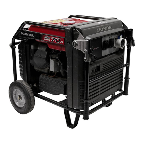
Page 10: Component Identification
COMPONENT IDENTIFICATION Example: B type CONTROL PANEL SPARK PLUG INSPECTION COVER HANDLE WHEEL BATTERY TRAY (Inside maintenance cover) FUSE (Inside maintenance cover) AIR CLEANER STAND FUEL TANK CAP FUEL GAUGE STARTER GRIP MUFFLER GROUND TERMINAL OIL DRAIN PLUG OIL FILLER CAP/DIPSTICK... - Page 11 FRAME SERIAL NUMBER Record the frame serial number in the space below. You will need this serial number when ordering parts. Frame serial number:...
-
Page 12: Control Panel
CONTROL PANEL EM50is/EM70is: B type OIL ALERT INDICATOR 115V RECEPTACLES OVERLOAD INDICATOR i-MONITOR BUTTON OUTPUT INDICATOR i-MONITOR 230V RECEPTACLE ENGINE SWITCH ECO THROTTLE SWITCH FUEL VALVE LEVER VOLTAGE SELECTOR SWITCH EM50is/EM70is: L type 120/240V RECEPTACLE 120V RECEPTACLES... - Page 13 EM50is/EM70is: F, G, GW types EM70is: IT type OIL ALERT INDICATOR 230V RECEPTACLES OIL ALERT INDICATOR 230V RECEPTACLE OVERLOAD OVERLOAD i-MONITOR i-MONITOR INDICATOR INDICATOR BUTTON BUTTON OUTPUT OUTPUT INDICATOR INDICATOR i-MONITOR i-MONITOR 240V RECEPTACLES ENGINE SWITCH ENGINE SWITCH FUEL VALVE LEVER...
- Page 14 Eco Throttle Engine speed is kept at idle automatically when the electrical appliance is disconnected and it returns to the proper speed by the electrical load when electrical appliance is connected. This position is recommended to minimize the fuel consumption while in operation. When high electrical load appliances is connected simultaneously, turn the Eco Throttle switch to the OFF position to reduce voltage changes.
- Page 15 Oil alert system The Oil Alert system is designed to prevent the engine damage caused by an insufficient amount of oil in the crankcase. Before the oil level in the crankcase can fall below a safe limit, the Oil Alert indicator comes on and the Oil Alert system automatically will stop the engine (the engine switch will remain in the ON position).
- Page 16 i-Monitor The i-Monitor is a user interface that allows the operator to view (when the generator is running) total operating time in hours, generator output, engine RPM, battery voltage and error messages. The different display modes are selected by pressing the i-Monitor button. i-Monitor at Start Up During start up, the i-Monitor display and all three indicators will simultaneously blink once.
- Page 17 i-Monitor Display Mode 1 Total Operating Hours This mode displays the total operating hours of the generator. When the generator is running, the total operating time accumulates. If the total operating time is less than one hour, the numeric display will be ‘‘0.’’...
- Page 18 Have the battery recharged and checked (see page i-Monitor System Error Messages If the generator has a system malfunction, it will show an error message on the i-Monitor display. If an error message display, contact an authorized Honda generator dealer. OVERLOAD INDICATOR ERROR MESSAGE (Example: E-01)
-
Page 19: Pre-Operation Check
PRE-OPERATION CHECK Be sure to check the generator on a level surface with the engine stopped. Check the engine oil level. Using nondetergent oil or 2-stroke engine oil could shorten the engine’s service life. Use high-detergent, premium quality 4-stroke engine oil, certified to meet or exceed U.S. - Page 20 Remove the oil filler cap, and wipe the dipstick with a clean rag. Check the oil level by inserting the dipstick in the filler hole without screwing it in. If the oil level is below the end of the dipstick, refill with recommended oil up to the top of the oil filler neck.
- Page 21 Check the fuel level. If the fuel level is low, refill to the shoulder of the fuel strainer. After refueling, tighten the fuel filler cap securely. Use automotive unleaded gasoline with a Research Octane Number of 91 or higher (a Pump Octane Number of 86 or higher). Never use stale or contaminated gasoline or an oil/gasoline mixture.
- Page 22 Gasolines containing alcohol If you decide to use a gasoline containing alcohol (gasohol), be sure it’s octane rating is at least as high as that recommended by Honda. There are two types of ‘‘gasohol’’: one containing ethanol, and the other containing methanol.
- Page 23 Check the air cleaner. Loosen the cover screws and remove the air cleaner cover. Remove the foam air filter from the air cleaner cover. Check the foam air filter to be sure it is clean and in good condition. If the foam air filter is dirty, clean it as described on page Replace the foam air filter if it is damaged.
-
Page 24: Starting The Engine
STARTING THE ENGINE Electric starting When starting the generator after adding fuel for the first time, after long-term storage, or after running out of fuel, turn the fuel valve lever to the ‘‘ON’’ position, then wait for 10 to 20 seconds before starting the engine. - Page 25 Make sure the EcoThrottle switch is in the OFF position, or more time will be required for warm up. (L type) (B type) ECO THROTTLE SWITCH ECO THROTTLE SWITCH (F, G, GW, IT types) (S, U, R types)
- Page 26 Turn the engine switch to the START position and hold it there until the engine starts. (S, U, R, L types) (B, F, G, GW, IT types) START ENGINE SWITCH Do not use the starter motor for more than 5 seconds. If the engine fails to start, release the key, and wait at least 10 seconds before operating the starter motor again.
- Page 27 If you wish to use the EcoThrottle system, turn the EcoThrottle switch to the ON position after the engine has warmed up for 2 or 3 minutes. (L type) (B type) ECO THROTTLE SWITCH ECO THROTTLE SWITCH (F, G, GW, IT types) (S, U, R types)
- Page 28 Manual starting When starting the generator after adding fuel for the first time, after long-term storage, or after running out of fuel, turn the fuel valve lever to the ‘‘ON’’ position, then wait for 10 to 20 seconds before starting the engine. Before starting the engine disconnect any load from the AC receptacle.
- Page 29 Make sure the EcoThrottle switch is in the OFF position, or more time will be required for warm up. (L type) (B type) ECO THROTTLE SWITCH ECO THROTTLE SWITCH (F, G, GW, IT types) (S, U, R types)
- Page 30 Turn the engine switch to the ON position. (S, U, R, L types) (B, F, G, GW, IT types) ENGINE SWITCH Pull the starter grip lightly until you feel resistance, then pull the starter grip briskly toward the arrow as shown below. Do not allow the starter grip to snap back.
- Page 31 If you wish to use the EcoThrottle system, turn the EcoThrottle switch to the ON position after the engine has warmed up for 2 or 3 minutes. (L type) (B type) ECO THROTTLE SWITCH ECO THROTTLE SWITCH (F, G, GW, IT types) (S, U, R types)
-
Page 32: High Altitude Operation
If you always operate the generator at altitudes higher than 1,500-meter (5,000 feet) above sea level, have your authorized Honda dealer perform these carburetor modifications. Even with suitable carburetor jetting, engine horsepower will decrease approximately 3.5% for each 300-meter (1,000-foot) increase in altitude. -
Page 33: Generator Use
GENERATOR USE Be sure to ground the generator when the connected equipment is grounded. Connections for standby power to a building’s electrical system must be made by a qualified electrician and must comply with all applicable laws and electrical codes. Improper connections can allow electrical current from the generator to backfeed into the utility lines. - Page 34 Limit operation requiring maximum power (see pages ) to 30 minutes. For continuous operation, do not exceed the rated power (see pages In either case, the total wattage of all appliances connected must be considered. Do not exceed the current limit specified for any one receptacle. Do not connect the generator to a household circuit.
- Page 35 AC applications B, L types only: Turn the voltage selector switch to either position. Type Voltage selector Used receptacles switch position 230V 230V 115V 115V 120/240V 120V and 120/240V 120V ONLY 120V B type: 230V L type: 120/240V B type: 115V L type: 120V ONLY VOLTAGE SELECTOR SWITCH Start the engine and make sure the Output indicator (green) comes...
- Page 36 Substantial overloading that continuously lights the Overload indicator (red) may damage the generator. Marginal overloading that temporarily lights the Overload indicator (red) may shorten the service life of the generator. Be sure that all appliances are in good working order before connecting them to the generator.
- Page 37 The chart below shows the rated load in amperes that can be connected to each receptacle to balance the generator when the 120/ 240 V locking plug receptacle is used for 120 V. The total rated ampere draw is: EM50is: 37.5A/EM70is: 45.8A Model Main power Receptacles powered...
- Page 38 When an electric motor is started, both the Overload indicator (red) and the Output indicator (green) may go on simultaneously. This is normal if the Overload indicator (red) goes off after about five (5) seconds. If the Overload indicator (red) stays on, consult your Honda generator dealer.
-
Page 39: Stopping The Engine
STOPPING THE ENGINE To stop the engine in an emergency, turn the engine switch to the OFF position. IN NORMAL USE: Switch off the connected equipment and pull the inserted plug. Turn the engine switch to the OFF position. (S, U, R, L types) (B, F, G, GW, IT types) ENGINE SWITCH Turn the fuel valve lever to the OFF position. -
Page 40: Maintenance
Service more frequently when used in dusty areas. These items should be serviced by your servicing dealer, unless you have the proper tools and are mechanically proficient. Refer to Honda shop manual for service procedures. For commercial use, log hours of operation to determine proper maintenance... - Page 41 CHANGING OIL Drain the oil while the engine is still warm to assure rapid and complete draining. Open and remove the oil maintenance cover. Remove the oil filler cap and oil drain plug to drain the oil. Install the oil drain plug, and tighten it securely. Refill with the recommended oil (see page ) and check the oil level.
- Page 42 AIR CLEANER SERVICE A dirty air cleaner will restrict air flow to the carburetor. To prevent carburetor malfunction, service the air cleaner regularly. Service more frequently when operating the generator in extremely dusty areas. Do not use gasoline or low flash point solvents for cleaning. They are flammable and explosive under certain conditions.
- Page 43 Clean the foam air filter in warm soapy water, rinse, and allow to dry thoroughly, or clean in nonflammable solvent and allow to dry. FOAM AIR FILTER Dip the foam air filter in clean engine oil, then squeeze out all excess oil.
- Page 44 FUEL SEDIMENT CUP SERVICE Gasoline is extremely flammable and is explosive under certain conditions. Do not smoke or allow flames or sparks in the area. You can be burned or seriously injured when handling fuel. Stop the engine and keep heat, sparks, and flame away. Handle fuel only outdoors.
- Page 45 SPARK PLUG SERVICE RECOMMENDED SPARK PLUG: BPR5ES (NGK) W16EPR-U (DENSO) To ensure proper engine operation, the spark plug must be properly gapped and free of deposits. Loosen the cover screw and remove the spark plug inspection cover. SPARK PLUG INSPECTION COVER COVER SCREW Disconnect the spark plug cap, and remove any dirt from around the spark plug area.
- Page 46 Visually inspect the spark plug. Discard it if the insulator is cracked or chipped. Clean the spark plug with a wire brush if it is to be reused. Measure the plug gap with a feeler gauge. Correct as necessary by carefully bending the side electrode. The gap should be: 0.70 0.80 mm (0.028 0.031 in) 0.70 0.80 mm...
- Page 47 In the event of fuse failure, locate the cause of failure and repair before you continue operation. If the fuse continues to fail, discontinue generator use and consult an authorized Honda generator dealer. Turn the engine switch OFF and remove the key before checking or replacing the fuse.
- Page 48 Remove the fuse holder cover and pull the fuse out. Replace the fuse with a fuse of the same type and rating. Specified fuse: 1A, 15A FUSES (1A) FUSE (15A) FUSE HOLDER FUSE HOLDER COVER If frequent fuse failure occurs, determine the cause and correct the problem before attempting to operate the generator further.
- Page 49 BATTERY REMOVAL/INSTALLATION Batteries produce explosive gases: If ignited, and explosion can cause serious injury or blindness. Provide adequate ventilation when charging. CHEMICAL HAZARD: Battery electrolyte contains sulfuric acid. Contact with eyes or skin, even through plathins, may cause severe burns. Wear a faceshield and protective clothing. Keep flames and sparks away, and do not smoke in the area.
- Page 50 Remove the battery from the battery tray. Installation: Make sure that the engine switch is turned OFF. Connect the battery positive ( ) cable to the battery positive ( ) terminal, then the battery negative ( ) cable to the battery negative ( ) terminal.
-
Page 51: Transporting/Storage
TRANSPORTING/STORAGE To prevent fuel spillage when transporting or during temporary storage, the generator should be secured upright in its normal operating position, with the engine switch OFF. The fuel valve lever should be turned OFF. When transporting the generator: Do not overfill the tank. Do not operate the generator while it is on a vehicle. - Page 52 Place an approved gasoline container below the sediment cup, and use a funnel to avoid spilling fuel. Remove the sediment cup, then move the fuel valve lever to the ON position (see page Allow the fuel to drain completely, then reinstall the sediment cup (see page Once a month, recharge the battery.
-
Page 53: Troubleshooting
To check: If the engine still Turn off the fuel valve does not start, lever and loosen the take the drain screw. generator to an Turn on the fuel valve authorized lever. Fuel should flow Honda dealer. from the drain. - Page 54 Appliance does not operate: Is the Output indicator ON? Take the Is the Overload generator to an indicator ON? authorized Honda dealer. Check the Take the electrical NO DEFECTS generator to an appliance or authorized equipment for Honda dealer. any defects.
-
Page 55: Specifications
SPECIFICATIONS Dimensions and Weight Model EM50is Description code EAJJ Length 810 mm (31.9 in) [extended handle] 1,155 mm (45.5 in) Width 670 mm (26.4 in) Height 690 mm (27.2 in) [extended handle] 710 mm (28.0 in) Dry weight 95 kg (209 lbs) - Page 56 Noise Model EM50is Type F, G, GW, B S, L, U, R Sound pressure level (Lp ) 81 dB According to 98/37/EC Microphone point CONTROL PANEL Center 1.60 m 1.0 m Guaranteed sound power level 96 dB ) Tested by 2000/14/EC at Eco Throttle Switch turn on Specifications are subject to change without notice.
- Page 57 Dimensions and Weight Model EM70is Description code EAHJ Length 810 mm (31.9 in) [extended handle] 1,155 mm (45.5 in) Width 670 mm (26.4 in) Height 690 mm (27.2 in) [extended handle] 710 mm (28.0 in) Dry weight 95 kg (209 lbs) Engine Model GX390K1...
- Page 58 Noise Model EM70is Type F, G, GW, B, IT S, L, U, R Sound pressure level (Lp ) 82 dB According to 98/37/EC Microphone point CONTROL PANEL Center 1.60 m 1.0 m Guaranteed sound power level 97 dB ) Tested by 2000/14/EC at Eco Throttle Switch turn on Specifications are subject to change without notice.
-
Page 59: Installation Of Kit Parts
INSTALLATION OF KIT PARTS STANDARD KIT PARTS Wheel Kit Installation Do not operate the generator without the wheel kit installed. The wheel kit provides an air space between the ground and the generator air intake. If the wheel kit is not installed, it may be possible for dirt and debris to be drawn into the generator air intake causing possible generator damage. - Page 60 Handle Installation Install the handle assembly on the generator upper frame using the 12 mm washers, spring washers and handle holder bolts. TORQUE: 24 29 N·m (2.4 3.0 kgf·m , 17 22 lbf·ft) SPRING WASHER (2) HANDLE HOLDER BOLT (2) 12 mm WASHER (2) HANDLE ASSEMBLY Operation must be checked after attaching a handle.
- Page 61 Rear Bar Installation Install the rear bar on the generator frame using the two 8 45 mm flange bolts. TORQUE: 24 29 N·m (2.4 3.0 kgf·m , 17 22 lbf·ft) 8 45 mm FLANGE BOLT (2) REAR BAR...
- Page 62 Battery The battery is either standard parts or optional parts for this generator. Battery Part Number: 31500-MCR-D02 Remove the maintenance cover (see page Standard parts type The battery is disconnected and strapped into the battery tray for shipment. Remove the battery strap from the bottom hook, and then remove the battery.
- Page 63 OPTIONAL KIT PARTS Remote Control Kit Remove the maintenance cover (see page Remove the plug from the 6-pin connector. PLUG View the back of the maintenance cover and locate the knockout near the top center of the cover. Carefully remove the knockout. KNOCKOUT...
- Page 64 Pass the remote control cable through the supplied wire grommet and fit the grommet into the maintenance cover knockout. Plug the remote control cable into the 6-pin connector. Install the maintenance cover and tighten the cover screw. REMOTE CONTROL CABLE REMOTE CONTROL CABLE REMOTE CONTROL BOX MAINTENANCE COVER...
- Page 65 Starting the engine with remote control: B, L types only: Determine the voltage requirements and adjust the voltage selector switch, as needed. Turn the fuel valve lever to the ON position. Turn the engine switch to the REMOTE (far left) position. (S, U, R, L types) (B, F, G, GW, IT types) REMOTE...
- Page 66 Stopping the engine: Press the stop button. (B, F, G, GW, IT types) (S, U, R, L types) STOP BUTTON Turn the engine switch to the OFF position. Turn the fuel valve lever to the OFF position. (S, U, R, L types) (B, F, G, GW types) REMOTE FUEL VALVE LEVER...
- Page 67 Hanger Kit Installation Position the hanger at the generator’s balance point as shown below. Fit the end tabs of the hanger through the bracket slots, and bolt the brackets to the hanger and tighten securely. TORQUE: 24 29 N·m (2.4 3.0 kgf·m , 17 22 lbf·ft) 8 16 mm FLANGE BOLT (4) HANGER BRACKET (2) HANGER...
-
Page 68: Wiring Diagram
WIRING DIAGRAM Auto Choke Motor L Type ACOR AC Output Receptacle Main Winding B Type Oil Alert Indicator Battery Overload Indicator Control Panel Block OLSw Oil Level Switch Combination Switch Output Indicator EcoSw Eco Throttle Switch R Type Engine Block Remote Control Block F Type RcBX... - Page 69 B type...
- Page 70 F, G, GW, IT type...
- Page 71 U, S, R type...
- Page 72 L type...
- Page 73 RECEPTACLE Shape Type G, GW...
- Page 74 RECEPTACLE Shape Type S, R...
-
Page 75: Major Honda Distributor Addresses
Honda Power Equipment Sweden AB Västkustvägen 17 Tel: 040-600 23 00 202 15 Malmö, Fax: 040-600 23 19 Sweden Honda Produtos De Força, Portugal, S.A. Lugar da Abrunheira Tel: 351-1-9150374 S. Pedro de Penaferrim Fax: 351-1-9111021 2710 Sintra, Portugal Berema A/S... - Page 76 2040 Buda-rs, Kamaraerdei-t 3. Tel: 23-444-971 Hungary Fax: 23-444-972 For Australian NAME OF FIRM (COMPANY) ADDRESS TEL: FAX: Honda Australia Motorcycle and Power 1954-1956 Hume Highway Tel: (03) 9270 1111 Equipment Pty. Ltd Campbelifield Victoria 3061 Fax: (03) 9270 1133...
- Page 77 GENERATOR EM50is EM70is • OWNER'S MANUAL MANUEL DE L'UTILISATEUR BEDIENUNGSANLEITUNG oHonda Motor Co., Ltd. 2004 efgsY1500.2006.04 36Z11604 MANUAL DE EXPLICACIONES Printed in Japan 00X36-Z11-6040...
Need help?
Do you have a question about the EM50is and is the answer not in the manual?
Questions and answers