Hitachi H 45MRY Technical Data And Service Manual
Hide thumbs
Also See for H 45MRY:
- Instruction manual (36 pages) ,
- Handling instructions manual (41 pages) ,
- Handling instructions manual (93 pages)

Related Manuals for Hitachi H 45MRY


Summary of Contents for Hitachi H 45MRY
- Page 1 MODEL H 45MRY Hitachi Power Tools DEMOLITION HAMMER TECHNICAL DATA H 45MRY SERVICE MANUAL Oct. 2006 LIST No.: E495 SPECIFICATIONS AND PARTS ARE SUBJECT TO CHANGE FOR IMPROVEMENT...
- Page 2 REMARK: Throughout this TECHNICAL DATA AND SERVICE MANUAL, symbols are used in the place of company names and model names of our competitors. The symbols utilized here are as follows: Competitors Symbols Utilized Model Name Company Name MAKITA HM0860C BOSCH GSH5E...
-
Page 3: Table Of Contents
8-8. Adjusting Mechanism for the Tool Swivel Angle ................15 8-9. Side Handle ..........................16 9. REPAIR GUIDE ..........................17 9-1. Precautions and Suggestions for Disassembly and Reassembly of the Main Body ....17 10. STANDARD REPAIR TIME (UNIT) SCHEDULES ..............28 Assembly Diagram for H 45MRY... -
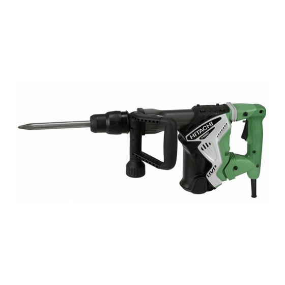
Page 4: Product Name
Hitachi Demolition Hammer, Model H 45MRY 2. MARKETING OBJECTIVE The Model H 45MRY is an upgraded version of the current Model H 45MR that features the use of maker B's SDS-max shank tools. The performance, durability and operability are greatly improved. In addition, the vibration... -
Page 5: Selling Points
4. SELLING POINTS Lowest vibration level in the class High chipping and demolishing performance with low vibration and noise level Self-chiseling (Good feeling) A highly reliable mechanism for prevention of idle hammering and shock-absorbing mechanism results in prolonged service life and comfortable operation. Newly designed vibration- absorbing handle Simply turning method, variable lock mechanism... -
Page 6: Selling Point Descriptions
The Model H 45MRY is equipped with Hitachi's own dynamic damper that absorbs vibration from the main body by means of resonance of a leaf spring and a spindle. As a result, the vibration level of the Model H 45MRY is remarkably lower than the current Model H 45MR. - Page 7 The Model H 45MRY has air holes located at the position unaffected by the rebound of the striker at no load. The air holes are opened and closed by the movement of the slide sleeve provided around the cylinder that interlocks with the tool and the second hammer to prevent idle hammering.
-
Page 8: Specifications
5. SPECIFICATIONS Power source Single-phase AC 50/60 Hz Voltage 110 V, 230 V AC single-phase series commutator motor Motor type Double insulation Insulation structure Enclosure Materials: Aluminum alloy die casting (Cylinder crank case) Nylon resin (Handle, tail cover, back cover, hood, crank cover) Polycarbonate resin (Housing) Paint: Green, gunmetallic silver, black, silver Switch... -
Page 9: Optional Accessories
5-1. Optional Accessories (1) Demolishing work (1) Bull point (SDS-max shank type) Overall length Code No. 280 mm (11-1/32") 313471 400 mm (15-3/4") 313472 (2) Grooving and chiseling work (1) Cold chisel (SDS-max shank type) Overall length Code No. 280 mm (11-1/32") 313473 400 mm (15-3/4") 313474... - Page 10 (4) Digging (Substitute pick-ax) (1) Scoop (SDS-max shank type) Overall length Code No. 400 mm (15-3/4") 313476 (5) Roughing surface work (1) Bushing tool (2) Shank (SDS-max shank type) Code No. Overall length Code No. 313477 220 mm (8-21/32") 313479 (6) Tamping work (1) Rammer (2) Shank (SDS-max shank type)
- Page 11 (7) Grease for hammer and hammer drill 30 g (1 oz) Tube 500 g (1.1 lbs.) Can 70 g (2.5 oz) Tube Code No. 981840 Code No. 980927 Code No. 308471 NOTE: Code numbers listed above are subject to change without notice. Please refer to periodic Technical News Bulletins.
-
Page 12: Comparisons With Similar Products
6. COMPARISONS WITH SIMILAR PRODUCTS 6-1. Specification Comparison HITACHI Maker Model name H 45MRY H 45MR Power input 1,100 1,100 Striking energy per stroke 12.5 1.8 to 12.0 2.0 to 12.0 12.7 Full-load impact rate 3,000 1,100 to 2,650 1,300 to 3,000... -
Page 13: Precautions In Sales Promotion
7. PRECAUTIONS IN SALES PROMOTION In the interest of promoting the safest and most efficient use of the Model H 45MRY Demolition Hammer by all of our customers, it is very important that at the time of sale the salesperson carefully ensures that the buyer seriously recognizes the importance of the contents of the Handling Instructions, and fully understands the meaning of the precautions listed on the Caution Plate attached to each tool. -
Page 14: Reference Information
8. REFERENCE INFORMATION Structure: Crank cover Connecting rod Second hammer O-rings Crank shaft Striker Cylinder Piston Air chamber Armature Fig. 2 8-1. Striking Operation The rotation of the armature is transferred to the crank shaft and the connecting rod, which in turn cause the piston to reciprocate inside the cylinder. -
Page 15: Dynamic Damper With Leaf Spring
Fig. 3 8-3. Vibration-proof Handle thanks to the Transatory Unit and the Neidhardt Spring The Model H 45MRY has the vibration-proof handle equipped with the transatory unit and the Neidhardt spring. Structure of the transatory unit The main body (cylinder crank case) is connected to... -
Page 16: Idling-Proof Mechanism
The Neidhardt spring prevents the handle from moving horizontally. Thus the Model H 45MRY can provide high vibration-proofing effect without Rebound hindering the operability by twisting. In addition, the handle is prevented from being pulled out (Fig. -
Page 17: Shock-Absorbing Mechanism
(A) as shown in Fig. 7 then the cushion (damper (A)) provided between hammer holder (A) and the front cover absorbs the striking force of the second hammer. Thus the durability of the Model H 45MRY is greatly increased because the second hammer does not strike the tool retainer directly. Second hammer... -
Page 18: Tool Retainer
8-7. Tool Retainer The Model H 45MRY is equipped with a slide-type tool retainer. Tools can be attached and detached just by pulling grip (A). While pulling grip (A) in A direction, insert the tool in the hole of the front cap (Fig. 9). Adjust the groove position by turning the tool and push it in to the end. -
Page 19: Side Handle
8-9. Side Handle The side handle can be adjusted by 360û rotation and also allows operation from front to rear. Loosen the handle by turning the grip in A direction and adjust the handle to a convenient position. Turn the grip in B direction to fix the side handle (Fig. -
Page 20: Repair Guide
9-1. Precautions and Suggestions for Disassembly and Reassembly of the Main Body The numbers in [Bold] correspond to the item numbers in the Parts List and the exploded assembly diagrams of the Model H 45MRY. 9-1-1. Disassembly Retainer disassembly (See Figs. 12 and 13.) Pull Grip (A) [2] fully in the arrow direction as shown in Fig. - Page 21 Removal of hammer holder (A), damper (A) and retainer sleeve Remove the Seal Lock Hex. Socket Hd. Bolt M6 x 25 [11] from the Front Cover [12]. Then the Front Cover [12] and the Retainer Sleeve [16] can be removed from the Cylinder Crank Case [47]. Insert a small flat-blade screwdriver into the groove of the Front Cover [12] and remove Ring (B) [20].
- Page 22 Removal of the first gear and the crank shaft Degrease the Connecting Rod [36] side and the First Gear [60] side of the Cylinder Crank Case [47]. Place the Cylinder Crank Case [47] on a workbench facing the Connecting Rod [36] side downward. Apply light pressure on the end surface of the Crank Shaft [42] with a hand press and pull out the Retaining Ring for D40 Hole [43] that fixes the Ball Bearing 6203DDCMPS2L [45] from the groove of the Cylinder Crank Case [47].
- Page 23 9-1-2. Reassembly Reassembly can be accomplished by following the disassembly procedure in reverse. However, special attention should be given to the following items. Mounting hammer holder (A) Set the Retainer Sleeve [16], O-ring (S-34) [14], Proper jig Damper (A) [17] and Hammer Holder (A) [18] in the Ring (B) Front Cover [12].
- Page 24 Mounting the piston Insert the Piston Pin [34] into the 8-mm dia. hole (marked) of the Piston [35] and the Connecting Rod [36] then press-fit it. Mount the O-ring (I.D 27.2) [33] to the Piston [35]. At this time, do not protrude the Piston Pin [34] from the outside of the Piston [35].
- Page 25 Move the crank pin of the Crank Shaft [42] then move the Piston [35] to the top dead center. Insert Spring (B) [32] into the cylinder case of the Cylinder Crank Case [47] then insert the assembly of the Cylinder [30], Slide Sleeve [31] and Striker [28] into the Cylinder Crank Case [47] (Fig.
- Page 26 Mounting the handle shaft and handle (A) Push the Holder [88] in the Back Cover [76] by hand. At this time, check that the clearance of the Holder [88] does not protrude from the main body and the Holder [88] does not protrude from the end surface of the Back Cover [76].
- Page 27 Mounting the leaf spring Sandwich the Leaf Spring [51] between Weight (A) [59] and Weight (B) [58] and fix it with the Leaf spring Seal Lock Hex. Socket Hd. Bolt M5 x 22 [56]. Weight (B) Weight (A) Sufficiently degrease the adhering surface of Weight (B) [58] and adhere Rubber Sheet (C) [57] securely.
- Page 28 Mount the assembly of the Leaf Spring [51], Weight (A) [59] and Weight (B) [58] to the Cylinder Crank Case [47]. Then mount Spring Bumper (A) [52] and Washer M4.5 [53] to the Cylinder Crank Case [47] in this order and fix it with the Seal Lock Hex.
- Page 29 Apply Hitachi Motor Grease No. 29 to the Needle Bearing (M661) [61], pinion portion of the Armature Ass'y [67], Needle Roller D8 x 20 [15] and Steel Ball D6.35 [10]. Seal 20 g of the Hitachi Motor Grease No. 29 into the Cylinder Crank Case [47] (the First Gear [60] side).
- Page 30 9-1-5. Internal wiring Wiring diagram for products with noise suppressor 9-1-6. Insulation tests On completion of disassembly and repair, measure the insulation resistance and the dielectric strength. Insulation resistance: 7 M Ω or more with DC 500 V megohm tester Dielectric strength: AC 4,000 V/1 minute, with no abnormalities 220 V --- 240 V •...
-
Page 31: Standard Repair Time (Unit) Schedules
10. STANDARD REPAIR TIME (UNIT) SCHEDULES Variable MODEL 60 min. Fixed Work Flow H 45MRY Housing Ass'y Stator Ass'y Handle (A).(B) Gear Cover Ass'y Transatory Unit Needle Switch (B) Bearing (A) Cord Handle Damper Armature Ass'y Handle Damper Ball Bearing... - Page 32 Hitachi Power Tools LIST NO. E495 ELECTRIC TOOL PARTS LIST HAMMER 2006 • • Model H 45MRY (E1)
- Page 33 PARTS H 45MRY ITEM CODE NO. DESCRIPTION REMARKS USED 315-529 FRONT CAP 320-802 GRIP (A) 320-803 RING 320-804 NEEDLE HOLDER 320-806 SPRING (A) 317-088 RETAINING RING D42 320-810 BALL HOLDER 320-807 GRIP (B) 320-808 GRIP (C) 959-150 STEEL BALL D6.35 (10 PCS.) 981-942 SEAL LOCK HEX.
- Page 34 PARTS H 45MRY ITEM CODE NO. REMARKS DESCRIPTION USED 326-477 WASHER M4.5 878-356 SEAL LOCK HEX. SOCKET HD. BOLT M4X10 878-418 NEEDLE ROLLER 317-245 SEAL LOCK HEX. SOCKET HD. BOLT M5X22 326-515 RUBBER SHEET (C) 326-508 WEIGHT (B) 326-507 WEIGHT (A)
-
Page 35: Standard Accessories
PARTS H 45MRY ITEM CODE NO. DESCRIPTION REMARKS USED 959-141 CONNECTOR 50092 (10 PCS.) 953-327 CORD ARMOR D8.8 500-390Z CORD 1 (CORD ARMOR D8.8) 500-454Z CORD 1 (CORD ARMOR D8.8) FOR GBR (110V) 500-446Z CORD 1 (CORD ARMOR D8.8) FOR GBR (230V)
Need help?
Do you have a question about the H 45MRY and is the answer not in the manual?
Questions and answers