Haier AFL631 series Service Manual

Haier AFL631 series Service Manual

Afl631/cfe633 series
Hide thumbs Also See for AFL631 series:

Advertisement

SERVICE MANUAL
Order No.Ref0905S003V0
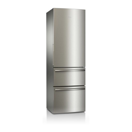
Refrigerator
MODEL:
AFL631*
CFE633*
WARNING
This service information is designed for experienced repair technicians only and is not designed for use by the general public. It
dose not contain warnings and cautions to advice non-technical individuals of potential dangers in attempting to service a product.
Product powered by electricity should by serviced or repaired only by experienced professional technicians. Any attempt to service
or repair the product or products dealt with in this service information by anyone else could result in serious injury or death.
◎2009(HAIER ELECTRICAL APPLIANCES COR. LTD)
All right reserved. Unauthorized copying and distribution is a violation of law。

Advertisement

Table of Contents
loading

Summary of Contents for Haier AFL631 series

  • Page 1 Product powered by electricity should by serviced or repaired only by experienced professional technicians. Any attempt to service or repair the product or products dealt with in this service information by anyone else could result in serious injury or death. ◎2009(HAIER ELECTRICAL APPLIANCES COR. LTD) All right reserved. Unauthorized copying and distribution is a violation of law。...
  • Page 2: Table Of Contents

    SERVICE MANUAL Issue 200905 Rev. Ref0905S003V0 Model: AFL631 & CFE633 Contents Table of Contents ·········································································································· 1 1. General Information ·································································································· 2 1-1. General guideline ······························································································· 1-2. Insurance test ····································································································· 1-3. How to read this Service Manual ········································································ 2. Product Feature ········································································································ 6 2-1.
  • Page 3 SERVICE MANUAL Issue 200905 Rev. Ref0905S003V0 Model: AFL631 & CFE633 4-2-1. Sensor location description ········································································ 4-2-2. Graphic display of the sensor location ······················································· 4-3. Self test model···································································································· 5. Control principle of electronic component ···························································· 23 5-1. Air Escaper ········································································································· 5-2. Control Principle of the Fan motor ······································································...
  • Page 4: General Information

    SERVICE MANUAL Issue 200905 Rev. Ref0905S003V0 Model: AFL631 & CFE633 Chapter 1 General Information 1-1. General Guidelines When servicing, observe the original lead dress. If a short circuit is found, replace all parts which have been overheated or damaged by the short circuit. After servicing, see to it that all the protective devices such as insulation barriers, insulation papers shields are properly installed.
  • Page 5: How To Read This Service Manual

    SERVICE MANUAL Issue 200905 Rev. Ref0905S003V0 Model: AFL631 & CFE633 Photo used in this manual The illustration and photos used in this Manual may not base on the final design of products, which may differ from your products in some way. 1-3.
  • Page 6: Product Feature

    SERVICE MANUAL Issue 200905 Rev. Ref0905S003V0 Model: AFL631 & CFE633 Chapter 2 Product Feature 2-1. SPECIFICATIONS Models AFL 631 CW/U CFE 633 CW/U AFL 631 CB/U CFE 633 CB/U AFL 631 CS/U CFE 633 CS/U Sketch Product description (Refrigerator/Freezer) Refrigerator Refrigerator Type of appliance (FS= freestanding/BI= built-in) Type of cooling system(NF=no frost/ S=static)
  • Page 7 SERVICE MANUAL Issue 200905 Rev. Ref0905S003V0 Model: AFL631 & CFE633 Energy consumption per l 100 net / 24h 0.87 0.87 Cooling system: K=Compressor / A=Absorption Max noise level dB(A) Aesthetics W/B/G W/B/G Colors: W=white G=silver gray SS=stainless steel F= flat / R= rounded / S= streamline Inside colour Compartments number...
  • Page 8: Main Functions And Features

    SERVICE MANUAL Issue 200905 Rev. Ref0905S003V0 Model: AFL631 & CFE633 Condenser Back wall / Integrated Product dimensions Unit dimensions ( H / W / D) 188/59.5/67 188/59.5/67 Depth Without handle 1188 1188 Depth with open door Door open angle n° <135 <135 Net weight...
  • Page 9: External Views

    SERVICE MANUAL Issue 200905 Rev. Ref0905S003V0 Model: AFL631 & CFE633 2-3. External views 2-3-1 Three-Door Refrigerator Structure Fridge storage compartment Display panel Turnover box (include egg box) Turnover box rack Shelf Butter box Wire wine holder Middle bottle rack Fresh keeping box cover Fresh keeping box Large bottle rack Crisper cover...
  • Page 10: Two-Door Refrigerator Structure

    SERVICE MANUAL Issue 200905 Rev. Ref0905S003V0 Model: AFL631 & CFE633 2-3-2 Two-Door Refrigerator Structure Display panel Turnover box Turnover box rack Shelf Butter box Middle bottle rack Fresh keeping box cover Fresh keeping box Large bottle rack Crisper cover Crisper Small bottle rack Freezer storage compartment drawer...
  • Page 11: Product Dimensions

    SERVICE MANUAL Issue 200905 Rev. Ref0905S003V0 Model: AFL631 & CFE633 2-4. Product Dimensions Three-Door Refrigerator Dimensions: Refrigerator height H=1880mm Refrigerator width W=595mm Refrigerator depth D=730mm Cabinet depth D1=576mm Door depth D2=78mm Two-Door Refrigerator Dimensions: Refrigerator height H=1880mm Refrigerator width W=595mm Refrigerator depth D=670mm Cabinet depth D1=576mm Door depth D2=78mm...
  • Page 12: Disassembly

    SERVICE MANUAL Issue 200905 Rev. Ref0905S003V0 Model: AFL631 & CFE633 Chapter 3 Disassembly 3-1 Installing the Freezer Drawer Handle (1) Take the handle from the packing bag and align it with the handle seat on the door. note: the screw hole on the handle should be facing downward. (2) Secure it with the screw from the bottom.
  • Page 13: Dismantles And Install The Upper Decoration Strip And Cables

    SERVICE MANUAL Issue 200905 Rev. Ref0905S003V0 Model: AFL631 & CFE633 ⑶ Lift the front decoration strip of the table-board outward and upward. At this time, there are wires connecting it. Please do not disconnect the wires. Gently put the front decoration strip on the top of the refrigerator.
  • Page 14: Dismantle And Install The Middle And Lower Hinge

    SERVICE MANUAL Issue 200905 Rev. Ref0905S003V0 Model: AFL631 & CFE633 (5) Pull the axis from the upper hinge. Then, insert it from the other end of the upper hinge. Insert the upper hinge by placing the axis into the door axis hole after turning 180 degrees. (6) Remove the stop block on the bottom of the door and then reatacht on the other side of the door after turning 180 degrees.
  • Page 15: Removing The Freezer Drawer

    SERVICE MANUAL Issue 200905 Rev. Ref0905S003V0 Model: AFL631 & CFE633 hinge. (4) Fix the lower hinge to the bottom of the other side of the cabinet. Then, mount the lower door on the lower hinge. (5) Take out the 3 hole plugs on the other side of the cabinet. Turn the middle hinge by 180 degrees and install it on the other side of the cabinet.
  • Page 16: Removing The Air-Duct

    SERVICE MANUAL Issue 200905 Rev. Ref0905S003V0 Model: AFL631 & CFE633 (3) Detach the screws fix on the top cover of the cabinet (fig.③); (4) Remove the top cover of the cabinet (fig.④); (5) Pull out the connector and remove the front decoration strip of the table-board (fig. ⑤⑥). 3-5 Removing the Air-Duct nplug the refrigerator before removing the air-duct 3-5-1 Removal of fridge air-duct...
  • Page 17 SERVICE MANUAL Issue 200905 Rev. Ref0905S003V0 Model: AFL631 & CFE633 (3) Remove the harness cover. There is a small indentation on both upper side and bottom side of the harness cover to facilitate the removal (fig ③); (4) Pull out the wires under the harness cover and pull out the connector (fig ④); (5) Detach the 2 screws in the freezing air-duct onto the freezer chamber (fig ⑤);...
  • Page 18: Control And Display System

    SERVICE MANUAL Issue 200905 Rev. Ref0905S003V0 Model: AFL631 & CFE633 Chapter 4 Control and display system 4-1. Control and display panel 4-1-1 Models: CFE633* Control panel Super cooling Fridge storage Power Freezer Super button temperature setup indicator storage freezing knob temperature button setup knob...
  • Page 19: Models: Afl631

    SERVICE MANUAL Issue 200905 Rev. Ref0905S003V0 Model: AFL631 & CFE633 it by pressing the super freezing button again. ■ Holiday function Turning the fridge storage temperature setup knob to “Holiday” will activate the holiday function of the fridge storage compartment. It will operate at a relatively high temperature. (Please remove any fresh food from the fridge storage compartment and close the door before activating this function) ■...
  • Page 20 SERVICE MANUAL Issue 200905 Rev. Ref0905S003V0 Model: AFL631 & CFE633 temperature inside. The freezer storage temperature will be displayed as“- -” due to high temperature inside. The buzzer will beep. Press key A9, and the buzzer will be silenced. After the temperature decreases to certain level, the displayed temperatures of the fridge storage compartment and the freezer storage compartment will become the ex-factory settings “5”...
  • Page 21: Error Code Display And Sensor Positions

    SERVICE MANUAL Issue 200905 Rev. Ref0905S003V0 Model: AFL631 & CFE633 ■ Turning off the fridge storage compartment Press and hold key A1 for 3 seconds, and the corresponding indicator will turn off and the fridge storage compartment will be turned off while the freezer storage compartment operates normally. The fridge storage temperature indication icon will also go off.
  • Page 22: Graphic Display Of The Sensor Location

    SERVICE MANUAL Issue 200905 Rev. Ref0905S003V0 Model: AFL631 & CFE633 4-2-2 Graphic display of the sensor location Ambient temperature sensor Fridge storage temperature sensor Defrosting temperature sensor Freezer storage temperature sensor 4-3. Self test model TEST1:Press the TEST key on the power board to enter the (PULL DOWN MODE), the door display panel displays T1 T1 and the refrigerator enters forced refrigeration state: the compressor operates normally, the fan runs at high speed, and the defrosting heating wire is disconnected.
  • Page 23: Control Principle Of Electronic Component

    SERVICE MANUAL Issue 200905 Rev. Ref0905S003V0 Model: AFL631 & CFE633 Chapter 5 Control principle of electronic component 5-1. Air Escaper (1) The refrigeration air door is controlled with the fridge storage temperature sensor R SNR. (2) The air door is closed from the beginning of defrosting until 15 minutes after the defrosting is finished.
  • Page 24: System Flow Principle

    SERVICE MANUAL Issue 200905 Rev. Ref0905S003V0 Model: AFL631 & CFE633 Chapter 6 System flow principle 6-1. Refrigeration flow chart Principle diagram and description of the refrigeration cycle The refrigerant is compressed in the compressor, from there, it enters the dry filter, de-dewing tube, and the condenser, and goes into the evaporator after being throttled and decompressed in the capillary tube.
  • Page 25: Perspective Of The Refrigeration System

    SERVICE MANUAL Issue 200905 Rev. Ref0905S003V0 Model: AFL631 & CFE633 6.2. Perspective of the Refrigeration System...
  • Page 26: Air Flow Scenograph

    SERVICE MANUAL Issue 200905 Rev. Ref0905S003V0 Model: AFL631 & CFE633 6.3 Air Flow Chart Schematic drawing and description of air circulation in the refrigerator air-duct...
  • Page 27: Circuit Diagram

    SERVICE MANUAL Issue 200905 Rev. Ref0905S003V0 Model: AFL631 & CFE633 Chapter 7 Circuit diagram 7-1. Main control PCB diagram Power board LED Lamp Display panel CON2 CON3 CON4 CON1 1 12 6 10 Main control cable Switch Blue Brown Black Air escaper connecting cable Fridge storage temperature sensor Defrosting temperature sensor...
  • Page 28: Main Control Pcb Connections

    SERVICE MANUAL Issue 200905 Rev. Ref0905S003V0 Model: AFL631 & CFE633 7-2. Main control PCB connections There are 4 connectors on the main control panel of CFE/AFL/AFD refrigerators. CN1 is the connector for the sensors and the door switch. Its pins from the left to right are: 1: GND 2: +12V 3: Door switch signal.
  • Page 29: Trouble Shooting

    SERVICE MANUAL Issue 200905 Rev. Ref0905S003V0 Model: AFL631 & CFE633 Chapter 8 Trouble shooting 8-1. Common problems and solutions 8-1-1 Symptom: food in the fridge storage compartment is frozen Check: 1) Verify that the temperature in the fridge storage compartment is too low and the food is frozen there; 2) Remove the decoration piece of the refrigeration air-duct.
  • Page 30: Neither Displaying Nor Starting When Powering On

    SERVICE MANUAL Issue 200905 Rev. Ref0905S003V0 Model: AFL631 & CFE633 2) Measure the resistance of the heating wire with a multimeter. It should be around 345Ω. 3) Measure the resistance of the defrosting fuse. If it is zero, the fuse is OK. If it is infinite, the fuse is malfunctioning.
  • Page 31: Examination And Solutions For Other Problems

    SERVICE MANUAL Issue 200905 Rev. Ref0905S003V0 Model: AFL631 & CFE633 8-2 Examination and Solutions for Other Problems Problems Causes Solutions Water/moisture/frost in the refrigerator Hot and moist climate. Accumulation frost moisture Moisture accumulates The door is not closed accelerate in such climate. on the refrigerators tightly Make sure the refrigerator is level and there...
  • Page 32 SERVICE MANUAL Issue 200905 Rev. Ref0905S003V0 Model: AFL631 & CFE633 fridge/freezer storage running time of the refrigerator in order to compartment is dirty, maintain desired temperature. worn, cracked or mismatched. Clean the condenser. The condenser is dirty. Too high temperature The door is opened too Warm will...
  • Page 33: Checking Flow Chart

    SERVICE MANUAL Issue 200905 Rev. Ref0905S003V0 Model: AFL631 & CFE633 8-3. Checking flow chart Com pressor doesn’ t start W hether lighting and display system is Trouble of lighting and display system normal W hether the grade of therm ostat is Adjust the grade according to fact on 0 W hether the...
  • Page 34 SERVICE MANUAL Issue 200905 Rev. Ref0905S003V0 Model: AFL631 & CFE633 Sincere forever Haier Group Haier Industrial Park, No.1, Haier Road 266101, Qingdao, China http://www.haier.com...

Table of Contents