Table of Contents
Advertisement
K40-CU-IM-13
1068155
Installation and Maintenance
Instructions
for
Air-Cooled, Remote and Water-Cooled
Condensing Units
National Refrigeration and Air Conditioning Canada Corp.,
159 Roy Blvd., P.O. Box 2020, Brantford, Ontario, N3T 5Y6
Phone: 800-463-9517, 519-751-0444 Fax: 519-753-1140
Visit our web site at www.keepriterefrigeration.com
Advertisement
Table of Contents
Troubleshooting

Related Manuals for KeepRite K40-CU-IM-13


Summary of Contents for KeepRite K40-CU-IM-13
-
Page 1: Installation And Maintenance
K40-CU-IM-13 1068155 Installation and Maintenance Instructions Air-Cooled, Remote and Water-Cooled Condensing Units National Refrigeration and Air Conditioning Canada Corp., 159 Roy Blvd., P.O. Box 2020, Brantford, Ontario, N3T 5Y6 Phone: 800-463-9517, 519-751-0444 Fax: 519-753-1140 Visit our web site at www.keepriterefrigeration.com... -
Page 2: Table Of Contents
Table of Contents Pages General Safety, Inspection & General Warranty Policy Handling, Placement & Installation 4 – 6 Electrical Information & Wiring Diagrams 7 – 14 Refrigerant Piping 15 – 16 Water-Cooled Condensers, Piping & Flow Rates 17 – 18 System Accessories Leak Testing, Evacuation &... -
Page 3: General Safety, Inspection & General Warranty Policy
General Safety IMPORTANT SAFETY NOTE Only a qualified refrigeration mechanic who is familiar with refrigeration systems and components, including all controls should perform the installation and start-up of the system. To avoid potential injury, use care when working around coil surfaces (if applicable) or sharp edges of metal cabinets. All piping and electrical wiring should be installed in accordance with all applicable codes, ordinances and local by-laws. -
Page 4: Handling, Placement & Installation
Handling, Placement and Installation IMPORTANT: When selecting a location for the condensing unit, consideration should be given to some of the following: Loading capacity of the floor or roof. Check building codes for weight distribution requirements. Distance to suitable electrical supply. Distance to the evaporator. - Page 5 SPECIAL NOTE FOR LARGE AIR COOLED CONDENSING UNITS: Vertical flow air cooled condensing units are large and heavy pieces of mechanical equipment and must be handled as such. A fully qualified and properly equipped crew with the necessary tackle and rigging should be engaged to locate the condensing unit into location.
- Page 6 Ventilation If the compressors or condensing units are to be located in machine rooms, adequate ventilation air must be provided in order to avoid an excessive temperature rise in the room. Air requirements vary with ambient air temperatures and the refrigeration load, however the following rule of thumb may be used to approximate ventilating air quantities: Model Type Air Quantity...
-
Page 7: Electrical Information & Wiring Diagrams
Electrical Information WARNING All wiring and connections to the unit must be made in accordance with national as well as local electrical codes and by-laws. Electrical wiring should be sized in accordance with the minimum circuit ampacities shown on the unit nameplate and applicable electrical codes. - Page 8 Electrical Wiring Diagram – Horizontal Air Flow Condensing Units (K-Line)
- Page 9 Electrical Wiring Diagram – Horizontal Air Flow Condensing Units (K-Line)
- Page 10 Electrical Wiring Diagram – Horizontal Air Flow Condensing Units (K-Line)
- Page 11 Electrical Wiring Diagram – Horizontal Air Flow Condensing Units (KE-Line)
- Page 12 Electrical Wiring Diagram – Horizontal Air Flow Condensing Units (KE-Line)
- Page 13 Electrical Wiring Diagram – Horizontal Air Flow Condensing Units (KE-Line)
- Page 14 Electrical Wiring Diagram – Vertical Air Flow Condensing Units...
-
Page 15: Refrigerant Piping
Refrigerant Piping WARNING All local codes must be observed in the installation of refrigerant piping. IMPORTANT PIPING NOTE Appropriate line sizing practices must be used throughout the installation of the refrigeration system. Special consideration must be taken when the condensing unit is installed above the evaporator. REFRIGERATION GRADE COPPER TUBING MUST BE USED FOR PIPING SYSTEMS. - Page 16 At the temperatures encountered in the condenser, receiver and liquid line a certain amount of oil is always being circulated with the refrigerant through the system by the compressor. However, at the evaporator temperature, and with the refrigerant in a vapor state, the oil and refrigerant separate. This oil can only be returned to the compressor by gravity or by entrainment in the suction gas.
-
Page 17: Water-Cooled Condensers, Piping & Flow Rates
Water-Cooled Condensers WARNING All water and drain connections to the unit must be made in accordance with national as well as local plumbing codes and by-laws. Cooling water circuits in some shell and tube water-cooled condensers may be either series or parallel as required by the particular application. - Page 18 If the condenser is installed more than 5 ft (1.52 m) higher than the outlet drain point of the condenser, a vacuum breaker or open vent line should be provided to prevent the outlet line from creating a partial vacuum condition. CONSULT THE FACTORY OR LOCAL SALES REPRESENTIVE FOR FURTHER INFORMATION.
-
Page 19: System Accessories
System Accessories In order to ensure trouble free operation of the refrigeration system it is important that the following system accessories be reviewed and installed. A moisture indicating LIQUID SIGHT GLASS should be installed in the liquid line between the receiver and as close as possible to the expansion valve on the evaporator. -
Page 20: Leak Testing, Evacuation & Dehydration
Leak Testing IMPORTANT: All system piping, including the condensing unit and accessories should be thoroughly tested for leaks prior to start up and charging. The system should be initially pressurized to a maximum of 150 psig (1136 kPa) with dry nitrogen to ensure that the system is free of major leaks. With the system free of major leaks, a more detailed leak check should be performed. -
Page 21: Line Insulation
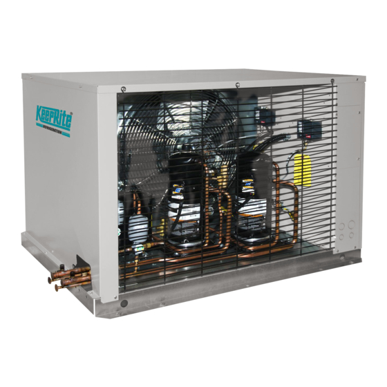
Line Insulation After the final system leak test is complete, it is important that all refrigerant lines exposed to high ambient conditions must be insulated to reduce the heat pick-up and prevent the formation of flash gas in the liquid lines. Suction lines should be insulated with 3/4 inch wall insulation, Armstrong “Armaflex”... - Page 22 Typical Air-Cooled Condensing Unit (with Horizontal Airflow Condensers) Refrigerant Operating Charges (LBS) (Less Evaporator and Liquid Lines) Cold Ambients ** (below 50 F) (outdoor Warm Ambients * (above 50 F) ambient winter operation with flooded head application pressure control) Model HP R-22 R-404A / R-507 Model HP...
- Page 23 Typical Air-Cooled Condensing Unit (with Vertical Airflow Condensers) Refrigerant Operating Charges (LBS) (Less Evaporator and Liquid Lines) COLD AMBIENTS** WARM AMBIENTS* AMBIENT TEMP. AMBIENT TEMP>50F +40F -40F +40F -40F TYPE R404A R404A 15 H 25.7 30.0 47.7 20 H 25.7 30.0 47.7 25 H...
-
Page 24: Compressor Oils
Compressor Oils Check to see that the oil level is 1/8 to 1/3 up on the compressor sight glass on compressors so equipped before starting the compressor and after 15 to 20 minutes of operation. CAUTION: Oil levels should not be allowed to go above the centre or 1/2 of the sight glass. Excessive oil levels in the compressor can result in excessive compressor noise, higher power consumption or internal compressor damage. - Page 25 Refrigeration Oils--Bitzer Semi-Hermetic Reciprocating Compressors: 2KC-05.2(Y) to 6F-50.2(Y) Interim Blends R-401A, R-401B, R-402A, HFC's (H)CFC R-408A, R-409A, R-134a, R-404A, Lubricant Type R-22 (MP-39, MP-66, HP-80, R-507, R-407C FX-10, FX56) ICI (Virgina KMP) Emkarate RL32S Polyol Ester Mobil EAL Arctic 32 Castrol Icematic SW32 Suniso 3GS Suniso 4GS...
-
Page 26: System Start-Up Check List
System Start-up Check List IMPORTANT START-UP NOTE Only a qualified refrigeration mechanic who is familiar with compressor performance and the function and adjustment of all controls and components should start up the compressor. Finishing up work on the installations should be planned so that a qualified mechanic is on the job for at least the first full day that the unit is in operation. -
Page 27: Low Temperature Room Pull-Down
Pressure Control Settings R-134a R-22 R-404A, R-507 Minimum Cut-in Cut-out Cut-in Cut-out Cut-in Cut-out Temperature (PSIG) (PSIG) (PSIG) (PSIG) (PSIG) (PSIG) 5" Hg 5" Hg 3" Hg * The coldest Temperature of either the fixture or outdoor ambient. High Pressure Control Settings Maximum Cut-out (PSIG) Refrigerant Air-Cooled Units... -
Page 28: Checking Compressor & Evaporator Superheat
Checking Superheat IMPORTANT SYSTEM BALANCING NOTE To obtain maximum system capacity and insure trouble free operation it is necessary to check both the compressor and evaporator superheat. Compressor Superheat Compressor suction superheat must be checked. To check the superheat at the compressor the following steps should be followed: Measure the suction pressure at the suction service valve of the compressor. -
Page 29: System Operational Check List
System Operational Check List When the system has been running trouble free for an extended time (two weeks or more) and design conditions are satisfied, the following check list should be followed: Check that compressor discharge and suction pressures are operating within the allowable design limits for the compressor. -
Page 30: System Troubleshooting
System Troubleshooting The following System Troubleshooting Guide lists the most common types of malfunctions encountered with refrigeration systems. These simple troubleshooting techniques can save time and money minimizing unnecessary downtime and end-user dissatisfaction. Contact the factory or your local sales representative for further information or assistance. System Troubleshooting Guide Condensing Unit Problem Possible Causes... - Page 31 Condensing Unit Problem Possible Causes Compressor noisy or vibrating. 1. Flood back of refrigerant. 2. Improper piping support on the suction or discharge lines. 3. Broken or worn internal compressor parts. 4. Incorrect oil level. 5. Scroll compressor rotating in reverse (three phase). 6.
-
Page 32: System Troubleshooting
System Troubleshooting Guide Fixture Problem Possible Causes Room temperature too high. 1. Defective room thermostat or improper differential / setting. 2. Malfunctioning liquid line solenoid valve. 3. Insufficient air across evaporator coil (iced up coil, product blocking evaporator, fan blade / motor problem). 4. -
Page 33: Customer Instructions
Customer Instructions Completely fill in Warranty Activation Certificate located inside of the back cover of this Installation and Maintenance Manual. The top (white) copy should be faxed or mailed per the instructions on this form. The (pink) copy is for the installing contractor’s files and the (yellow) copy is to be left attached inside of the Installation and Maintenance Manual for the owner / end user’s future reference. -
Page 34: Finished Goods Warranty & Service Log
FINISHED GOODS WARRANTY The terms and conditions as described below in the General Warranty Policy cover all products manufactured by National Refrigeration. GENERAL WARRANTY POLICY Subject to the terms and conditions hereof, the Company warrants all Products, including Service Parts, manufactured by the Company to be free of defects in material or workmanship, under normal use and application for a period of one (1) year from the original date of installation, or eighteen (18) months from the date of shipment from the Company, whichever occurs first. -
Page 35: Warranty Activation Certificate
Start-up Information Important: This start-up information should be completely filled in on each installation and remain with the unit as a permanent record for future reference. Future service work may be logged on the proceeding page. Service parts list are attached to the back cover. PLEASE PRINT LEGIBLY ___________________________________________________ Name &... -
Page 36: Service Parts List
Service Parts List National Refrigeration & Air Conditioning Canada Corp. CANADA 159 ROY BLVD., BRANTFORD, ONTARIO, CANADA N3R 7K1 985 WHEELER WAY, LANGHORNE, PA. 19047 USA PHONE: 1-800-463-9517 (519)751-0444 FAX (519)753-1140 PHONE:1-888-KEEPUS1 OR 1-888-533-7871 Due to National Refrigeration’s policy of continuous product improvement, we reserve the right to make changes without notice. 08/08/2007...
Need help?
Do you have a question about the K40-CU-IM-13 and is the answer not in the manual?
Questions and answers