Table of Contents
Advertisement
Quick Links
Advertisement
Table of Contents
Troubleshooting

Related Manuals for Sangoma Netborder SS7


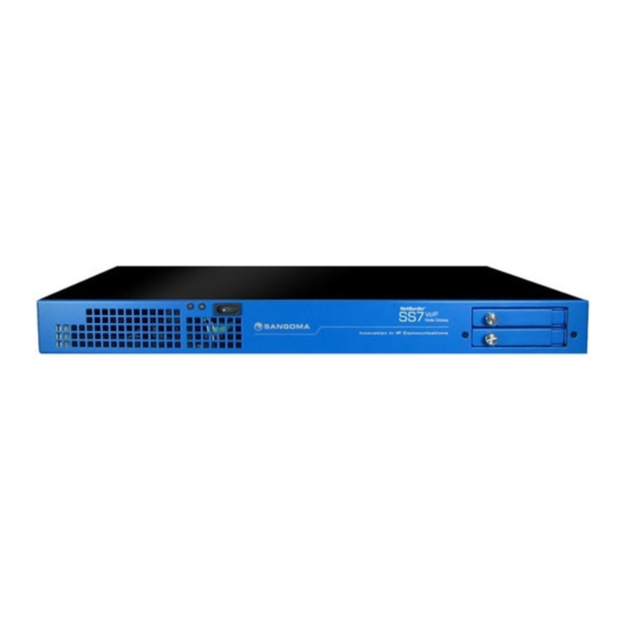
Summary of Contents for Sangoma Netborder SS7
-
Page 1: User Manual
Netborder SS7 to VoIP Gateway User Manual [Type the abstract of the document here. The abstract is typically a short summary of the contents of the document. Type the abstract of the document here. The abstract is typically a short summary of the contents of the document.]... - Page 2 NOTE Notes inform the user of additional but essential information or features. CAUTION Cautions inform the user of potential damage, malfunction, or disruption to equipment, software, or environment. Sangoma Technologies provides technical support for this product. support@sangoma.com Tech-support e-mail: v1.14...
- Page 3 This page is intentionally blank. v1.14...
-
Page 4: Sangoma
Sangoma Netborder SS7 to VoIP GW User Manual v1.14... -
Page 5: Table Of Contents
Contents Sangoma............................... 4 Netborder SS7 to VoIP GW User Manual ..................... 4 Product Overview .......................... 10 Features / Advantages ......................10 1.1.1 Any to Any Signaling and Media Gateway ..............11 TDM T1/E1 Interfaces ......................12 Ethernet Network Interfaces ....................12 VoIP Protocols ........................ - Page 6 3.2.2 Connect via USB Serial ....................32 3.2.3 Bash Shell ........................33 Gateway CLI – nsg_cli ....................34 3.2.4 Shell/CLI from GUI ......................... 35 Usage Scenarios ........................... 36 Signaling Gateway: M2UA ....................36 Megaco/H.248 Media Gateway: MG + SG ................36 4.2.1 Megaco Quick Configuration ...................
- Page 7 Megaco/H.248 Media Gateway Configuration ................74 Overview ..........................74 8.1.1 Terminations........................74 8.1.2 Contexts .......................... 74 Commands ..........................75 8.2.1 Sent from controller to gateway ..................75 8.2.2 Sent from gateway to controller ..................75 Packages ..........................76 Create MG Profile ........................77 Create MG Peer Profile ......................
- Page 8 10.1.2 Configuring the slave gateway ..................136 10.1.3 Configuring the slave TDM configurations from the master gateway ......140 Media Transcoding Configuration ................... 142 11.1 Media Hardware ....................... 143 Applying Configuration ......................144 Dialplan ........................... 146 13.1 Dialplan Reload/Apply ...................... 147 13.2 PSTN to SIP Dialplan .......................
- Page 9 Troubleshooting ........................188 19.1 Physical Layer ........................189 19.1.1 NSG TDM Driver related commands ................190 19.1.2 T1/E1 Port Status ......................191 19.1.3 T1/E1 Port Debugging ....................191 19.2 TDM Signaling Link Debugging ..................195 Appendix ..........................197 20.1 Redundant DC PSU ......................197 20.1.1 DC PSU Cables ......................
-
Page 10: Product Overview
1 Product Overview The NetBorder SS7 to VoIP Gateway is Sangoma’s Carrier Class TDM to SIP VoIP Gateway product. For short, it is often referred to as NSG. 1.1 Features / Advantages Any to any switching gateway. o Ability to run all endpoints/protocols on single software image and appliance o SS7, Sigtran, SIP, H.323, Megaco Media Gateway, Signaling Gateway... -
Page 11: Any To Any Signaling And Media Gateway
1.1.1 Any to Any Signaling and Media Gateway Route any signaling traffic from eny signaling endpoint. All protocols and signalling suppored from single gateway image. o Ability to change from Megaco GW to SIP gateway via config change. ... -
Page 12: Tdm T1/E1 Interfaces
1.2 TDM T1/E1 Interfaces Electrical G.703.6/G.704 balanced Minimum 4 T1/E1 Maximum 32 T1/E1 (960 ds0/sessions) per appliance Transcoding supported on all channels Extend capacity over 960 ports via ISUP relay feature and multiple appliances. 1.3 Ethernet Network Interfaces ... -
Page 13: H.323
H.248.2 – Fax etal Package H.248.14 – Inactivity Timer Package Augmented BNF for Syntax Specifications: ABNF, Internet RFC 2324 DTMF support o RFC 2833/4733 - "RTP Payload for DTMF Digits, Telephony Tones and Telephony Signals" o In-band DTMF detection/generation 1.4.3 H.323 Call Handling ... -
Page 14: Isdn
1.5.2 ISDN CCITT 88, User & Network Side PRI/BRI AT&T 4ESS User Side - PRI, Network Side - PRI 5ESS User Side - PRI/BRI, Network Side - PRI/BRI DMS-100 User & Network Side - PRI/BRI ETSI User &... -
Page 15: Echo Cancellation & Vqe
SIP INFO Hardware and software DTMF detection and generation 1.10 Management and Configuration Sangoma NSG configuration, operation and troubleshooting are designed to be flexible. Web GUI Profile Sync, on the fly configuration without service interruption. Command line interface via ssh and usb to serial ... -
Page 16: Shipping Options
Up to 32 E1/T1, ISUP to SIP, codec support, 32 signaling links, up to 12 point codes 1.14 Support and Professional Services Sangoma Engineers are here to support your success. Whether you need technical support and software maintenance, training, consultation and installation services, Sangoma can help you. Please contact your Sales representative for more information. -
Page 17: Nsg Product Information
2 NSG Product Information 2.1 NetBorder SS7 to VoIP Gateway Appliance Fully integrated Industrial grade telco appliance running a customized OS, Netborder SS7 to VoIP application and TDM interfaces configured and installed by Sangoma. NSG Appliance provides a full-featured, carrier-class VoIP deployment while leveraging the flexibility and cost effectiveness of standard computing platforms. -
Page 18: Nsg Shipping Box Contents
2.2 NSG Shipping Box Contents The first three tasks for installing and operating the Netborder SS7 to VOIP Gateway are Unpack Inspect Power up. Carefully inspect the NSG Appliance for any damage that might have occurred in shipment. -
Page 19: Front Panel
Refer to Serial Console section. RAID1 SSD o The RAID1 is NOT Hot Plug o NSG appliances use industrial grade SSD o One must power down the machine in order to change SSD/HDD o Contact Sangoma Support for part replacement. v1.14... -
Page 20: Rear Panel 1U
2.2.4 Rear Panel 1U Power button o Used to turn off the power supply o Not for Factory Reset USB Ports can be used for Serial Console o Refer to Serial Console section. PSTN T1/E1 Interfaces o RJ45 Connections ... -
Page 21: Front Panel 2U
Refer to Factory Reset section. RAID1 SSD o The RAID1 is NOT Hot Plug o NSG appliances use industrial grade SSD o One must power down the machine in order to change SSD/HDD o Contact Sangoma Support for part replacement. v1.14... -
Page 22: Rear Panel 2U
2.2.6 Rear Panel 2U 2.2.6.1 Rear Panel Description Fan Internal Power supply o Default AC, non-redundant o Option: DC or AC Redundant Power Button o Used to turn off the machine o Not used for Factory Reset. ... -
Page 23: Nsg T1/E1 Port Identification
2.3 NSG T1/E1 Port Identification Sangoma T1/E1 Interface boards come with two types of RJ45 Connections Low density Interface Boards o Single Port Interface Board o Dual Port Interface Board o Quad Ports Interface Board o RJ 45 Connector ... -
Page 24: Cable Pinouts: T1/E1
2.3.1 Cable Pinouts: T1/E1 NSG Appliance utilizes Sangoma TDM T1/E1 digital board adapters. A101DE – 1-port E1/T1 board A102DE – 2-port E1/T1 board A104DE – 4-port E1/T1 board A108DE – 8-port E1/T1 board* Eight Port Board Information... - Page 25 T1/E1 "Portsplitter" Cable T1/E1 Split Cable for the Eight Port Board Standard | ROHS: Yes | Length: 6' SKU: CABL-630 A108D Loop Back Cable This is to connect an A108 port in loopback mode 1 <-> 4 2 <-> 5 3 <->...
-
Page 26: Nsg Appliance Default Configuration
2.4 NSG Appliance Default Configuration By default the NSG appliance gets shipped with following configuration. Static IP 192.168.168.2 / 255.255.255.0 Static IP Port eth0 (Primary Ethernet Interface Port) WebUI URL http://192.168.168.2:81 Username root Password sangoma v1.14... -
Page 27: User Interface
3 User Interface Netborder SS7 to VoIP media gateway provides the user with two interfaces WebGUI o Web GUI is preferred for almost all operations o Configuration, Operations, Statistics, Reports Console via ssh or usb-serial o For power users familiar with Linux operating system, ssh or usb-serial console provides advanced and flexible interface for troubleshooting and automation. -
Page 28: Webgui Structure
3.1.1 WebGUI Structure 3.1.1.1 Overview Control Panel o Used to control the global gateway operations: start, stop, restart Profile Panel o Used to Sync configuration on the fly without Restarting full gateway. o Allows configuration of the gateway without service interruption. o Supported from NSG Version v5.0.1 ... - Page 29 Allow for system software and hw components test. o Firmware Update Allows for firmware updates Sangoma TDM boards Sangoma Media processing boards Help o About Shows system version and version of all important packages. o PBX Integration ...
- Page 30 o Hardware Report Full hardware overview and description HDD, Memory and system usage Device enumeration o Resource Report Long term statistics v1.14...
-
Page 31: Console Structure
3.2 Console Structure Console access via ssh Console access via usb-serial Shell Commands via WebUI – Command Execution Gateway CLI Commands via WebUI – Command Execution Operating system is Linux based. Therefore Linux expertise is mandatory. ... -
Page 32: Connect Via Usb Serial
3.2.2 Connect via USB Serial usb to serial cable o One must use usb to serial cable + null modem cable o If Laptop does not have a serial port then use two usb to serial cables plus null modem cable per diagram below. -
Page 33: Bash Shell
Network interface statistics tool o Shows error counters on Ethernet and TDM interfaces. o Notice the error and overrun counters on wanpipe w1g1 interfaces. wanpipemon o Sangoma TDM troubleshooting tool o T1/E1 alarms wanpipemon –i w1g1 –c Ta nsg_cli... -
Page 34: Gateway Cli - Nsg_Cli
3.2.4 Gateway CLI – nsg_cli First log into the System Console (bash) Once on bash prompt run o nsg_cli NOTE The NSG gateway must be running and started in Control Pannel. Command Description status Shows NSG Status show channels List all active calls ftdm list... -
Page 35: Shell/Cli From Gui
3.3 Shell/CLI from GUI Select Command Execution from side/top Configuration Menu Specify a shell or CLI command. Refer to guide below. Warning Do not run shell commands that run indefinitely. Such as “ping <ip>”. In such case the webgui will get stuck forever executing the command. -
Page 36: Usage Scenarios
Pass through signaling from IP to TDM o M2UA -> MTP2 4.2 Megaco/H.248 Media Gateway: MG + SG Third part Softswitch/MGC controlling Netborder SS7 Media Gateway using Megaco/H.248 protocol. o Bridge RTP media to TDM Voice 64kb G.711 channels o Bridge TDM Voice 64kb G.711 channels to RTP media ports... -
Page 37: Megaco Quick Configuration
4.2.1 Megaco Quick Configuration In order to configure the system for Megaco Operation Perform the First Boot/Initial Setup o Section 5 o Connect and Power up the system o Change password Perform the Network Connection o Section 6 o Setup IP, VLAN and Routes ... -
Page 38: Sip/H323 To Ss7 Isup
4.3 SIP/H323 to SS7 ISUP Bridge signaling sessions from H.323 to SS7 ISUP o Bridge RTP media to TDM Voice 64kb G.711 channels Bridge signaling session from SS7 ISUP to H.323 o Bridge TDM Voice 64kb G.711 channels to RTP media ports ... -
Page 39: H323 To Ss7 Isup Quick Start Guide
4.3.1 H323 to SS7 ISUP Quick Start Guide In order to configure the system for Megaco Operation Perform the First Boot/Initial Setup o Section 5 o Connect and Power up the system o Change password Perform the Network Connection o Section 6 o Setup IP, VLAN and Routes ... -
Page 40: Any To Any Signaling And Media Gateway
4.4 Any to Any Signaling and Media Gateway Route any signaling traffic from eny signaling endpoint simultaneously. Ability to run all protocols together at the same time. Route media with transcoding/dtmf/T.38 to/from end media endpoint. v1.14... -
Page 41: First Boot/Initial Setup
Initial Provision Done Next step is to configure the Gateway. o Please refer to usage scenarios in section 5. 5.1 Power Connection Sangoma NSG comes with three types of power supplies AC PSU o AC Single PSU (Default) o AC Dual-Redundant PSU ... -
Page 42: Dc Psu Connection
5.1.2 DC PSU Connection Connecting cables to a power supply depends on the remote power source. Power Source Type Black Wire Red Wire If power source -48V -48V 0V (Ground) If power source +48V 0V (Ground) +48V The PSU has voltage reverse protection. If the red and black wires are connected the wrong way, the system will not power up. -
Page 43: Establishing Initial Webgui Connection
Connect the Primary Signaling Port: eth0 to a LAN Switch Connect Laptop to LAN Switch Configure Laptop to IP address: 192.168.168.1/24 Using Laptop web browser go to URL: http://192.168.168.2:81 Login via o Username: root, Password: sangoma v1.14... -
Page 44: Change Password
5.3 Change Password After successful Login, please proceed to change the default password. Sangoma NSG appliance comes with default password. For security reasons please change the password. Select Password page from side/top System menu Enter your new password ... -
Page 45: Console Ssh Configuration
5.4 Console SSH Configuration By default NSG systems come with SSH enabled. To configure ssh service Select Services from side/top System Menu Enable or disable Secure Shell service v1.14... - Page 46 Service Description Status Samba/Windows NetBIOS Windows NetBIOS server Not used / Not required MySQL MySQL database Not used / Not required Samba/Windows Server Windows File server Not used / Not required Time Server Network Time Protocol Should be configured and enabled.
-
Page 47: Self Test
5.5 Self Test Self-Test page must be run on initial installation or on any hardware upgrade. It will run a battery of tests on Sangoma TDM and Transcoding hardware. 5.5.1 Running Self-Test Select Self Test from side/top System Menu ... - Page 48 ARNING All services during the Self-Test will be stopped. The existing configuration will be restored after Self Test. Do not run Self-Test in production! Only run Self-Test during on initial setup or during a maintenance window. The Self-Test can be used to detect: ...
-
Page 49: Nsg License
5.6 NSG License Each NSG appliance comes with pre-installed license. In case of upgrades, of expansions please contact Sangoma Sales. To update NSG license Select License from side/top Configuration Menu Obtain NSG License from Sangoma Support Upload the License into the NSG Gateway via the Upload Button The License page offers the detailed license overview. - Page 50 License Variables Description Name Customer Name Email Customer Email Reseller Reseller Name License SPC stands for: self point code It’s used to bind a specific set of point codes to the license. ANY: is a special value which allows use of an SPC value. System’s MAC address.
-
Page 51: Network Configuration
6 Network Configuration Network configuration section only applies to Physical Network Interfaces: eth0 and eth1. It does not apply to VLAN IP and route configuration. Network Setup Physical network interfaces: eth0, eth1 are configured in the section Configuration-> Settings-> IP Settings. This section can only be used to modify/configure IP, Host, DNS information for Physical Network interfaces eth0 and eth1. - Page 52 Media Ethernet Interface: Transcoding NSG comes with optional, media/codec transcoding hardware. The media transcoding hardware network interface is: eth2. The media transcoding network interface comes preconfigured with a 10.x.x.x ip address. Configuration of the eth2 device should be performed in Configuration->Settings->Media. CAUTION One should take this into account when assigning IP addresses to eth0,eth1 or VLAN interfaces.
-
Page 53: Physical Network Interface Configuration
Select Edit under eth0 and eth1 device and configure NOTE eth2 device is a Sangoma Transcoding device and should be modified. eth2 device is configured in Configuration -> Media section of the GUI will configure this device. -
Page 54: Appliance Network Interfaces
By default provisioned as static no IP address o By default allows access to ssh and management http eth2 o Sangoma transcoding DSP board o Provisioned using Media page. Do not modify in this section. 6.3 Selecting Default Route NSG appliance should have a single default route. -
Page 55: Network Section
6.4 Network Section Variable Name Input Options Description Standalone – No Firewall Mode Firewall Disabled Standalone Firewall Enabled Warning: All active service ports must be explicitly enabled Hostname String A hostname is the full name of your system. If you have your own domain, you can use a hostname like nsg.example.com Alternatively, you can also make one up: gateway.lan, mail.lan. -
Page 56: Interface Section
6.5 Interface Section 6.5.1 Network Role When configuring a network interface, the first thing you need to consider is the network role in IP Settings. Will this network card be used to connect to the Internet, for a local network, for a network with just server systems? The following network roles in IP Settings are supported in NSG and are described in further detail in the next sections: ... -
Page 57: Types
Option Description External Network interface with direct or indirect access to the Internet External interface is used as the system default route. ARNING You should have only ONE external network interface. Usually eth0 is the external interface Connection to your local network Usually eth1 is the LAN interface Hot LAN (or “Hotspot Mode”) allows you to create a separate LAN network for Hot LAN... -
Page 58: Ethernet Options
6.5.3 Ethernet Options Setting custom Ethernet options such as disabling auto negotiation is done as part of the IP Settings. Select IP Settings from side/top Configuration Menu Specify Options field in order to add special configuration to this interface. Options are any device-specific options supported by ethtool. -
Page 59: Virtual Ip's
6.6 Virtual IP’s NSG supports virtual IPs. To add a virtual IP address, click on the link to configure a virtual IP address and add specify the IP Address and Netmask. You will also need to create advanced firewall rules if the virtual IP is on the Internet. 6.7 IP Troubleshooting In most installs, the network cards and IP settings will work straight out of the box. -
Page 60: Static Routes
6.8 Static Routes In some cases a static route must be defined for a specific network interface: eth0 or eth1. The static route support is done via File Editor Select IP Route from side/top Configuration Menu Add a custom route command ... - Page 61 Route File Name Description Usage Use to create static routes for Primary Signaling Ethernet Port:eth0 Usage: {-host|-net} Target[/prefix] [gw Gw] [metric M] [netmask N] [mss Mss] [window W] [irtt I] [mod] [dyn] [reinstate] [[dev] If] Example: #Route a class C network 10.133.20.0 via gw IP -net 10.133.20.0 netmask 255.255.255.0 gw 10.132.30.1 #Route a class B network 10.133.0.0 via gw IP -net 10.133.0.0 netmask 255.255.0.0 gw 10.132.30.1...
-
Page 62: Routing Table Status
6.8.1 Routing Table Status Select VLAN Status from side/top Overview Menu Second table shows full system routing table. v1.14... -
Page 63: Vlan
6.9 VLAN Virtual local area network, virtual LAN or VLAN is a concept of partitioning a physical network, so that distinct broadcast domains are created. NSG mark’s packets through tagging, so that a single interconnect (trunk) may be used to transport data for various VLANs. A VLAN has the same attributes as a physical local area network (LAN), but it allows for end stations to be grouped together more easily even if not on the same network switch. -
Page 64: Vlan Configuration
6.9.1 VLAN Configuration Currently NSG only supports VLAN configuration via GUI Select VLAN from side/top Configuration Menu Copy in the VLAN configuration script below into the file editor Save o On save the VLAN configuration will be applied o Proceed to VLAN Status confirm VLAN configuration. -
Page 65: Vlan Routes
Example of sample script that could be copied into the VLAN config startup script: #Create a VLAN device on eth0 interface with VLAN ID of 5 vconfig add eth0 5 #configure VLAN device with IP/Net mask ifconfig eth0.5 192.168.1.100 netmask 255.255.255.0 broadcast 192.168.1.255 up #configure a default route within a vlan route add –net 192.168.1.0/24 gw 192.168.1.1 #if system default route needs to go through VLAN... -
Page 66: Additional Vlan
6.9.3 Additional VLAN If more VLAN’s are needed, proceed to repeat the above steps for all VLANs. When Save button is pressed The VLAN configuration will be applied The script above will be executed line by line. Status window will pop up with VLAN config status. If one of the lines fails, the pop up will report it. -
Page 67: Vlan Status
6.9.5 VLAN Status Select VLAN Status from side/top Overview Menu This page shows o All configured VLANs o System Routing table o Individual VLAN configuration o Individual VLAN IP information v1.14... - Page 68 NOTE Confirm that VLAN Interface contains the correct IP address. If the IP address is not set, the VLAN configuration has not been set properly. v1.14...
-
Page 69: Date & Time Service Config
6.10 Date & Time Service Config The Date/Time configuration tool allows you to: Select your time zone Synchronize your clock with network time servers Enable/disable a local time server for your network Note that you need to configure your IP address and default route in order to be able to use a default time server that is located on the internet. - Page 70 Option Description Date/Time The system date, time and time zone information is displayed for informational purposes. Please make sure it is accurate since it is not unusual to have computer clocks improperly set on a new installation. Time Zone It is important to have the correct time zone configured on your system. Some software (notably, mail server software) depends on this information for proper time handling.
-
Page 71: Initial Gateway Configuration
7 Initial Gateway Configuration NSG by default contains following VoIP/TDM Sections Global Gateway Config o Configured in Global gateway section. o Used to configure SIP, H323, RTP, RADIUS options. SIP/RTP o Configured in Global Gateway section o SIP profile is always started ... -
Page 72: Global Gateway Configuration
7.1 Global Gateway Configuration Select Global from side/top Configuration Menu Change a SIP global variable and Click on Save (Disk Icon) Proceed to Control Panel and Restart the VoIP Gateway. v1.14... - Page 73 Any string Sangoma NSG SIP incoming registration authentication password outbound_caller_name Any string Netborder SS7 Global caller id name defaults (used if no caller id to VoIP Media name is present on the call) for both PSTN and Gateway outbound_caller_id Any digits...
-
Page 74: Megaco/H.248 Media Gateway Configuration
8 Megaco/H.248 Media Gateway Configuration 8.1 Overview H.248 or Megaco or Gateway Control Protocol is a recommendation from ITU which defines protocols that are used between elements of a physically decomposed multimedia gateway. It is an implementation of the Media Gateway Control Protocol Architecture (RFC 2805). H.248 is also called Megaco or in IETF domain. -
Page 75: Commands
The normal, "active" context might have a physical termination (say, one DS0 in a DS3) and one ephemeral one (the RTP stream connecting the gateway to the network). Contexts are created and released by the MG under command of the MGC. A context is created by adding the first termination, and it is released by removing (subtracting) the last termination. -
Page 76: Packages
A MEGACO-configured NSG starts by sending a Service Change command to its MGC. When an MGC accepts the NSG registration, the session can start. Subsequently, the NSG responds to MGC commands. Event notifications are sent only if the MGC requests them specifically. 8.3 Packages Additional features are provided in packages, which define additional properties, events and signals that are included in the descriptors used in the protocol’s commands. -
Page 77: Create Mg Profile
8.4 Create MG Profile Media gateway profile will contains all the required configuration parameters to bring up the Media gateway stack. Select MG from the side/top Configuration menu Select Add New Profile o Use default profile name, or specify one ... -
Page 78: Default Values
Followings are the fields, that need to be configured. Field Name Possible Default Description values Values Protocol MEGACO MEGACO Type of protocol Media Gateway is going to use. MGCP NOTE: Currently Media Gateway supports only MEGACO Message Type IP-PORT IP-PORT Media gateway message identifier (MID) type Identifier field will be used to build the message identifier... - Page 79 through as G711 stream. RTP IP any ipv4 addr Same as Signaling Megaco RTP source IP address. By default it should be set to SIgnaling IP address, this way both signaling and media originate from single IP address. In VLAN scenarios it’s possible to use separate IP addresses for Signaling and RTP.
-
Page 80: Create Mg Peer Profile
8.5 Create MG Peer Profile Each Media gateway profile will associate with one or multiple peers. NOTE: As of now NSG supports only “one peer per MG profile”. Select Add Peer in MG Section Fill in the peer information ... - Page 81 Field Name Possible Default Description values Values Message Identifier IP-PORT IP-PORT Media gateway Controller message identifier Type (MID) type field will be used by Media Gateway to identify the peer. Message identifier value will be built based on MID type field. For example: If MID type is IP-PORT then Message identifier format will be...
-
Page 82: Tdm Termination For Media Gateway
8.6 TDM Termination for Media Gateway Select TDM from side/top Configuration menu The TDM section will display all installed TDM Spans/Ports. v1.14... -
Page 83: Identify
1. The image is not meant to reflect the real hardware image, nor real port location. User should always view the rear panel for the flashing LED. All Sangoma TDM T1/E1 cards Port 1 is closest to the PCI slot. v1.14... -
Page 84: Edit T1/E1 Config
8.6.2 Edit T1/E1 Config Once the port has been identified and plugged into the T1/E1 network. Select Edit button for Port 1 Card 1 to configure the physical T1/E1 parameters. Select the port configuration type: T1 or E1 o T1: North American Market and Japan o E1: Europe and the world ... - Page 85 In case advanced parameters are not necessary proceed Apply to Port o Applies the configuration for a single T1/E1 port o (The one that is currently being edited) Apply to all Ports o Apply to all T1/E1 ports on a board. o Bulk config feature o (This feature saves time as T1/E1 ports are usually provisioned the same) v1.14...
- Page 86 8.6.2.2 Advanced T1/E1 Parameters NOTE After T1/E1 configuration, the NSG wizard will request Link Type Configuration. v1.14...
-
Page 87: Span Link Type
8.7 Span Link Type When configuring TDM Terminations for Megaco Media Gateway there are two possibilities Voice Mode o All TDM channels are used for Voice 64kbs G.711 o Example: All channels 1-31 on an E1 line are used for voice o Link Type = Voice Only ... -
Page 88: Signaling Gateway Overview
8.8 Signaling Gateway Overview NSG supports Signaling Gateway operation mode. In Signaling gateway mode, NSG will bridge T1/E1 SS7 signaling link to IP and pass it transparently to the MGC/Softswitch, via M2UA protocol. Looking at the diagram below, NSG Signaling Gateway will configure: ... -
Page 89: Mtp1/2 Link Configuration
8.8.1 MTP1/2 Link Configuration Specify MTP1/2 information based on provider provision document Step1: Identify which channel on T1/E1 line will carry signaling Step2: Specify MTP2 signaling information based on provision document Step3: Specify M2UA Interface ID based on provision document ... - Page 90 Field Name Possible Default Value Description Values Link Name M2UA Profile name Span Span number which is going to associated with this M2UA profile. Line Media E1/T1 Media type Type Signaling Signaling channel of the span which will carry the channel M2UA signaling messages.
-
Page 91: M2Ua Interface
8.8.2 M2UA Interface This section provides in-depth overview on how the M2UA interface is constructed. It should help the user better understand the WebUI configuration objects for M2UA protocol. WebUI for M2UA contains 3 sections: Cluster, Peer and SCTP SCTP interfaces are standalone objects on which a peer bind to (regardless of its cluster). o 1 SCTP binds to 1 or more peers o 1 peer binds to 1 SCTP o Thus SCTP are shared across all peers... -
Page 92: M2Ua Cluster Creation
8.8.3 M2UA Cluster Creation M2UA Cluster is a group of peers to which M2UA SG will communicate Select Create Cluster Leave the Cluster values default unless the provider specifies otherwise. Select Save to Continue Field Name Possible Default Value Description Values... -
Page 93: M2Ua Cluster Peers
8.8.4 M2UA Cluster Peers M2UA Peers will be configured under the M2UA clusters Select Add under Cluster Peers Profile Select Create Cluster Peer Profile Specify the Cluster Peer parameters based on provider provision document Field Possible Values Default Value Description Name... - Page 94 Include Disable Disable Flag used to indicate whether include the Enable ASP ID in the ASP UP message Identifier ASP identifier for this ASP node. Identifier Set to 1 in case ASP is Disabled Initialize Disable Disable Flag used to indicate if M2UA SG has to start SCTP SCTP Enable association or not.
-
Page 95: Sctp Interface
8.8.5 SCTP Interface Select Add SCTP Interface Select Create SCTP Interface Specify SCTP Information based on provider provision document v1.14... -
Page 96: Binding All Components
8.8.6 Binding all components All components have been created o M2UA Cluster o M2UA Peer o SCTP Interface Next step is to Bind / Connect them together o SCTP interface into M2UA Peer o M2UA peer into M2UA Cluster v1.14... -
Page 97: Mixed Mode Configuration
8.8.7 Mixed Mode Configuration Signaling is bridged by M2UA to the MGC/Soft switch Voice is controlled by Megaco/H.248 Specify that Voice is part of this TDM Span NOTE Rest of this section will document the Mixed Mode Configuration v1.14... -
Page 98: Bind Megaco To Tdm
8.8.8 Bind Megaco to TDM The last step of the configuration is to bind the TDM voice channels to Megaco Profile. v1.14... - Page 99 Field Possible Values Default Value Description Name Media List of Gateways First in the List Select Megaco Profile that will be used to control the TDM Gateway channels for this span. Profile Termination Usually a letter A-Z. This prefix is defined by MGC. ID Prefix Please refer to MGC configuration.
- Page 100 Channel Map: 1-15,s16,17-31 (signaling on ch 16) A1: channel 1 A2: channel 2 … A15: channel 15 … A16: not used – A16 points to signaling channel 16 A17: channel 17 A18: channel 18 … A31: channel 31 Channel Map: 1-15,g16,17-31 (signaling on ch 16) A1: channel 1 A2: channel 2 A15: channel 15...
-
Page 101: Tdm Termination Complete
8.8.9 TDM Termination Complete A span has been configured and bound to a Megaco Profile. Configuration for this span is done o Confirmed in WebUI by a green checkmark. Next step is to repeat the process for the rest of the spans. ... -
Page 102: Ss7 Isup
9 SS7 ISUP SS7 is a signaling protocol, it is used to carry call control information such as call start, call progress, call hangup etc. The SS7 call control information is used to control arbitrary number of voice channels that are carried using T1/E1 spans. In a typical SS7 setup the telco will provide you with SS7 information that will be used to map T1/E1 physical spans and channels into SS7 call control information. - Page 103 3. Once all T1/E1 spans are configured you need to Apply the configuration files. Note that this step does not start the NSG gateway. It just writes the appropriate configuration files. 4. Proceed to the Control Panel to start the NSG SS7 to VoIP Gateway. v1.14...
-
Page 104: Tdm Ss7 Configuration Page
9.1 TDM SS7 Configuration Page Select TDM from side/top Configuration menu The TDM section will display all installed TDM Spans/Ports. The TDM Configuration page will display to the user every T1/E1 card detected by NSG. Each card is logically separated into ports, which initially displays the firmware version and the Echo Cancellation security chip ID. -
Page 105: Port Identification
1. The image is not meant to reflect the real hardware image, nor real port location. User should always view the rear panel for the flashing LED. All Sangoma TDM T1/E1 cards Port 1 is closest to the PCI slot. v1.14... -
Page 106: Edit T1/E1 Config
9.3 Edit T1/E1 Config Once the port has been identified and plugged into the T1/E1 network. Select Edit button for Port 1 Card 1 to configure the physical T1/E1 parameters. Select the port configuration type: T1 or E1 o T1: North American Market and Japan o E1: Europe and the world ... - Page 107 In case advanced parameters are not necessary proceed Apply to Port o Applies the configuration for a single T1/E1 port o (The one that is currently being edited) Apply to all Ports o Apply to all T1/E1 ports on a board. o Bulk config feature o (This feature saves time as T1/E1 ports are usually provisioned the same) v1.14...
-
Page 108: Advanced T1/E1 Parameters
9.3.2 Advanced T1/E1 Parameters NOTE After T1/E1 configuration, the NSG wizard will request Link Type Configuration. v1.14... -
Page 109: Span Link Type
9.4 Span Link Type When configuring TDM Terminations for Megaco Media Gateway there are two possibilities Voice Mode o All TDM channels are used for Voice 64kbs G.711 o Example: All channels 1-31 on an E1 line are used for voice o Link Type = Voice Only ... -
Page 110: Ss7 Network Overview
9.5 SS7 Network Overview v1.14... -
Page 111: Links
9.5.1 Links physical signaling links between the TX board and the adjacent signaling points. One link configuration must be performed for each physical signaling link. The attributes of a link include the point code of the adjacent signaling point, protocol variant employed on the link (ITU-T or ANSI), point code length, maximum packet length, various timer values, membership in a linkset, and others. -
Page 112: Mtp2 Link Configuration
9.6 MTP2 Link Configuration Proceed to configure the SS7 ISUP link that exists on a DS0 timeslot of a T1/E1 port. The information required for the SS7 Link configuration must be provided by the Telco. Next screen will confirm if the T1/E1 port contains a signaling link. ... - Page 113 The following screen will configure the MTP1 and MTP2 protocol configuration of the SS7 Link. CAUTION The SLC configuration value MUST be unique for each SS7 Link, in case all SS7 Links belong to same Link Set. Click on Apply to Port button to proceed to next configuration section v1.14...
- Page 114 Field Possible Default Description Name Values Value Link Any String Link1 Name to identify the SS7 Link. By default the GUI will select a unique Name name. However it is sometimes useful to specify a SS7 Link name that relates to the remote destination. Span This is readonly information field.
-
Page 115: Mtp3 Linkset Configuration
MTP3 Digit Default traffic priority for this link. Priority Switch ITU00 ITU00 MTP3 protocol supports different variants Type ITU97 ITU92 Outside North America ITU88 ITU and ETSI standards are used ETSI V2 In North America ETSI V3 ANSI standards are used. RUSSIA INDIA ANSI92... - Page 116 Click on Create Profile once the configuration is completed. NOTE On very fist Linkset profile, the Link will automatically be BINDED to the Linkset. Field Possible Values Default Description Name Value Profile Any String Name to identify the SS7 Linkset. By default the GUI will select a Name unique name.
- Page 117 If ITU Single integer number: eg 500 If ANSI Three integers separated by dash: eg 100-200-400 Please refer to your Telco provider for this information. Minimum Integer 1-X A Linkset can contain number of SS7 Links. Active This field defines how data should be distributed across links in a Signaling linkset.
-
Page 118: Mtp3 Ss7 Route
9.8 MTP3 SS7 Route Route is a collection of linksets to reach a particular destination. A linkset can belong to more than one route. Service Provider personnel statically maintain signaling endpoint routing tables. The routing table identifies the links, linksets, primary routes, and alternate routes for each DPC. All links in the linkset share the traffic load equally. - Page 119 The user will only need to edit a route if a new linkset is created on the system. If no new linksets are created, the user will proceed directly to the channel map and CIC map configuration Field Possible Values Default Description Name...
-
Page 120: Isup Interface Configuration
9.9 ISUP Interface Configuration ISUP connects, manages, and disconnects all voice and data calls in the PSTN. ISUP sets up and tears down the circuits used to connect PSTN voice and data subscribers.. ISUP is used in cellular or mobile networks for trunking connections. ISUP information is transferred in MTP3 messages similar to the other L4 protocols. - Page 121 Field Possible Values Default Description Name Value Profile Any String ISUP1 Name to identify the SS7 ISUP Interface profile. By default the GUI Name will select a unique name. However it is sometimes useful to specify a SS7 ISUP Interface name that relates to the remote destination.
- Page 122 Sefl Point Code is the address of the NSG SS7 Gateway in the SS7 network. If ITU (outside North America) Single integer number: eg 500 If ANSI (North America) Three integers separated by dash: eg 100-200-400 Please refer to your Telco provider for this information. National National Please confirm with your provider which value to use.
- Page 123 12-15 isup.t33 isup_interface isup.t34 isup_interface 15-20 isup.t35 isup_interface 10-15 isup.t36 isup_interface v1.14...
-
Page 124: Isup Cic Channel Mapping
9.10 ISUP CIC Channel Mapping The last step of the configuration is to bind the TDM voice channels to ISUP Profile and map ISUP CIC’s to the TDM timeslots. v1.14... - Page 125 Field Possible Values Default Description Name Value Profile Any String Name to identify the SS7 Call Control profile. By default the GUI will Name select a unique name. However it is sometimes useful to specify a SS7 ISUP Interface name that relates to the remote destination. ISUP List of existing ISUP Current...
- Page 126 Prefix Letters to signaling channel: s: ISUP CIC id not used, id mapped to signaling channel g: ISUP CIC id is used, id mapped to next available voice channel. The bind between ISUP and TDM would be as follows Channel Map: 1—31 (no signaling channel) CIC 1: channel 1 CIC 2: channel 2 …...
- Page 127 Field Possible Values Default Description Name Value Minimum Integer Enables overlap dialing in ISUP. Incoming Overlap Dialing ISUP List of existing ISUP Current ISUP Interface points to the list of currently defined ISUP Interface Interface Interface profiles Profile profiles. v1.14...
- Page 128 Each ISUP profile defines its own Self-Point-Code/Origination Code. With multiple ISUP profiles, one can configure a system with multiple Self-Point-Codes. Selected ISUP Interface Profile will be used to control the physical TDM T1/E1 DS0 channels. CIC Base Integer 1 to Any Start of the ISUP CIC numbers.
- Page 129 Channel Map: 1-15,s16,17-31 (signaling on ch 16) CIC 1: channel 1 CIC 2: channel 2 … CIC 15: channel 15 … CIC 16: not used – A16 points to signaling channel 16 CIC 17: channel 17 CIC 18: channel 18 …...
-
Page 130: Relay: Ss7
10 Relay: SS7 NSG SS7 relay enables a single NSG gateway (master) to control multiple NSG gateways (slaves) with as little as 1 signaling link connected to the master. You can have up to 8 slave machines that are controlled by a single master gateway. Signaling messages (MTP2 traffic) are passed over the IP network to the slave machines. -
Page 131: Relay Configuration
10.1 Relay Configuration To access the Relay: SS7 configuration section 1. Select Relay from side/top Configuration Menu Select if you do not want to enable Relay mode in your installation and proceed to the next to resume SS7 configuration. section ... -
Page 132: Configuring The Master Gateway
10.1.1 Configuring the master gateway We will start by configuring the master machine first. Select the Master option in step 2 and click "Next Step" to continue. v1.14... - Page 133 In Step 3, you will generate an SSH key and download the public key that will be uploaded to all the slave gateways. This key will enable a secure SSH connection between the master and the slave machines to push the configurations. The Relay Master will listen for incoming relay traffic on port 5000.
- Page 134 Once the SSH key has been generated you will need to click on the "Add New Host" button to add 1 or more slave gateways to the relay configuration. The listening relay port for all subsequent slave instances will increase by 1 port. Slave on node 2 will listen on port 5001, Slave on node 3 will listen on port 5002, etc...
- Page 135 Once you have configured all your slave hosts, you can now configure your slave machine(s) v1.14...
-
Page 136: Configuring The Slave Gateway
10.1.2 Configuring the slave gateway To access the Relay: SS7 configuration section 1. Select Relay from side/top Configuration Menu Select YES in step 1 to enable Relay mode. v1.14... - Page 137 Select the SLAVE option in step 2 and click "Next Step" to continue. v1.14...
- Page 138 Upload the public key that you downloaded and saved when you configured the master gateway earlier. v1.14...
- Page 139 Once the key has been uploaded, the SSH link will have been enabled. Repeat these steps for all the slave machines and return to the master WebUI when you are finished. v1.14...
-
Page 140: Configuring The Slave Tdm Configurations From The Master Gateway
10.1.3 Configuring the slave TDM configurations from the master gateway Open the master WebUI in your browser. 1. Select TDM from side/top Configuration Menu The TDM configuration is presented in a tabbed pane, each tab represents a machine to configure. Select the Slave tab to configure the slave gateway. - Page 141 Once you have completed configuring the master and slave(s) TDM configurations, you will click on the "Generate config" button that will push the configuration to each slave over a secure SSH connection. All this is done from the convenience of the master server's WebUIgateway’s web gui, removing the need to log on to each slave server's WebUIgateway’s individually.
-
Page 142: Media Transcoding Configuration
11 Media Transcoding Configuration NSG will enable ALL Media Codec’s by default. There is no extra configuration needed. Use this configuration page in case you want to limit which codecs should be enabled, or disable media codec support. To access NSG Media Transcoding Configuration ... -
Page 143: Media Hardware
11.1 Media Hardware Once Codec selection has been made, proceed to Advanced Options section of the Media page. Select SCAN o This step will auto-detect all NSG transcoding resources Confirm that GUI detected exact number of transcoding resources as installed. ... -
Page 144: Applying Configuration
12 Applying Configuration The changes made in the Configuration section of the WebUI are only stored one the scratch disk. User MUST proceed to Apply page in the Management Section to save new configuration. Select Apply from side/top Configuration Menu ... - Page 145 NOTE After configuring the NSG endpoint/protocol configuration, proceed to Dialplan to configure the routing rules. v1.14...
-
Page 146: Dialplan
13 Dialplan When a call is received in the NetBorder SS7 Gateway, from SIP,H232 or SS7 the dialplan is fetched to retrieve the route information to find the outgoing call location. Note: Dialplan is not used in MG/Megaco/H.248 mode: MGC performs the routing. -
Page 147: Dialplan Reload/Apply
Dialplan is pre-configured for SIP to TDM and TDM to SIP Bridging. Section "from-sip" routes calls from SIP to PSTN/SS7 Section "from-pstn" routes calls from PSTN/SS7 to SIP. H.323 to TDM and TDM to H.323 Bridging Section “from-h323” routes calls from H.323 to PSTN 13.1 Dialplan Reload/Apply Note that Dialplan can be modified in real time without the need to restart the gateway. -
Page 148: Pstn To Sip Dialplan
13.2 PSTN to SIP Dialplan By default NSG is setup to send an call to a SIP IP address. The remote SIP address must be configured in Configuration -> Global section. <context name="from-pstn-to-sip"> <extension name="to-sip"> <!-- handle the case where there might not be destination number at all --> <condition field="destination_number"... -
Page 149: Pstn To H323 Dialplan
13.3 PSTN to H323 Dialplan By default NSG is setup to send a call to an H323 IP address. The remote H323 address must be configured in Configuration -> Global section. <context name="from-pstn-to-h323"> <extension name="to-h323"> <!-- handle the case where there might not be destination number at all --> <condition field="destination_number"... -
Page 150: Sip/H323 To Pstn Dialplan
13.4 SIP/H323 to PSTN Dialplan Note that both SIP and H323 profiles share the same “from-sip” context name name. The from-sip context will pass all calls to TDM interfaces. <?xml version="1.0" encoding="utf-8"?> <include> <context name="from-sip"> <extension name="to-pstn"> <!-- retrieve group and hunting parameters if present --> <condition field="destination_number"... -
Page 151: Dialplan Syntax
13.5 Dialplan Syntax There are several elements used to build an XML dialplan. In general, the dialplan groups logically similar functions and calling activities into a 'context'. Within a context are extensions, each with 'condition' rules and associated 'actions' to perform when the condition rules match. The following is a sample dialplan to illustrate these concepts. -
Page 152: Context
13.5.1 Context Contexts are a logical grouping of extensions. You may have multiple extensions contained within a single context. The context tag has a required parameter of 'name'. There is one reserved name, any, which matches any context. The name is used by incoming call handlers (like the [Sofia] SIP driver) to select the dialplan that runs when it needs to route a call. -
Page 153: Extensions
13.5.2 Extensions Extensions are destinations for a call. This is the meat of NSG routing dialed numbers. They are given a name and contain a group of conditions, that if met, will execute certain actions. A 'name' parameter is required: It must be a unique name assigned to an extension for identification and later use. -
Page 154: Conditions
13.5.3 Conditions Dialplan conditions are typically used to match a destination number to an extension. They have, however, much more power than may appear on the surface. NSG has a set of built-in variables used for testing. In this example, the built-in variable destination_number is compared against the regular expression ^500$. -
Page 155: Multiple Conditions (Logical And)
13.5.4 Multiple Conditions (Logical AND) You can emulate the logical AND operation available in many programming languages using multiple conditions. When you place more than one condition in an extension, all conditions must match before the actions will be executed. For example, this block will only execute the actions if the destination number is 500 AND it is Sunday. -
Page 156: Multiple Conditions (Logical Or, Xor)
13.5.5 Multiple Conditions (Logical OR, XOR) It is possible to emulate the logical OR operation available in many programming languages, using multiple conditions. In this situation, if one of the conditions matches, the actions are executed. For example, this block executes its actions if the destination number is 501 OR the destination number is 502. - Page 157 <action application="sleep" data="500"/> <action application="playback" data="ivr/ivr-welcome_to_freeswitch.wav"/> <action application="sleep" data="500"/> </condition> <condition field="${calling_user}" expression="^loser$"> <action application="playback" data="ivr/ivr-dude_you_suck.wav"/> <anti-action application="playback" data="ivr/ivr-dude_you_rock.wav"/> </condition> </extension> <extension name="Regex XOR example 3" continue="true"> <condition regex="xor"> <!-- If only one of these is true then the subsequent actions are added to execute list --> <regex field="caller_id_name"...
- Page 158 <condition regex="any"> <regex field="${sip_from_host}" expression="domainA"/> <regex field="${sip_from_uri}" expression="1234567890@domainB"/> <regex field="${sip_from_uri}" expression="user@domainC"/> <regex field="caller_id_name" expression="^(John Smith)$"/> <regex field="caller_id_number" expression="^(55512341)|(55512342)|(55512343)$"/> <action application="set" data="domain_name=domainZ"/> <action application="transfer" data="${destination_number} XML domainZ"/> </condition> </extension> This is another example to show that all regex conditions must be true, then the action will get executed;...
-
Page 159: Complex Condition/Action Rules
<anti-action application="bridge" data="user/1000@${domain_name},sofia/gateway/1006_7217/${mobile_number}"/> </condition> 13.5.6 Complex Condition/Action Rules Here is a more complex example, performing time-based routing for a support organization. The user dials extension 1100. The actual support extension is 1105 and is staffed every day from 8am to 10pm, except Friday, when it is staffed between 8am and 1pm. - Page 160 of extension processing. This example sets the variable begins_with_one if the destination number begins with 1. <extension name="break-demo"> <!-- because break=never is set, even when the destination does not begin with 1, we skip the action and keep going --> <condition field="destination_number"...
-
Page 161: Variables
13.5.7 Variables Condition statements can match against channel variables, or against an array of built in variables. 13.5.7.1 Built-In Variables The following variables, called 'caller profile fields', can be accessed from condition statements directly: context Why can we use the context as a field? Give us examples of usages please. ... - Page 162 For example: <condition field="network_addr" expression="^192\.168\.1\.1$"/> <!-- network address=192.168.1.1 > <condition mon="2"> <!-- month=February --> 13.5.7.2 Caller Profile Fields vs. Channel Variables One thing that may seem confusing is the distinction between a (the built-in variables) caller profile field and a channel variable. Caller profile fields are accessed like this: <condition field="destination_number"...
-
Page 163: Backup Restore System
14 Backup Restore System Appliance configuration can be backed up to a zipped file. Appliance can be restored from a same file. Select Backup from side/top Configuration Menu Click on Backup and Download Now o Note that a backup will be offered for download as well as stored locally on the system. o Note the Backup Archive shows previous backups that can be used to restore the system. -
Page 164: Restore A System
14.1 Restore a System The default scenario for system Restore is to recover an existing system from factory reset, or to recover to another system, due to system failure CAUTION After a system has been restored via WebGUI a reboot is mandatory. After a reboot ... -
Page 165: Restore To A New System
This is not recommended and requires expert level understanding of the backup files and manual configuration files. Which defeats the purpose of the WebGUI. NOTE Sangoma has a product roadmap plan for mass system provisioning. If this is of interest please contact Sales. v1.14... -
Page 166: Factory Reset & Reboot
15 Factory Reset & Reboot 15.1 Factory Reset Find a power button in front of the NSG Appliance Press the power button repeatedly fast (every 1 sec) for 10 sec. On factory reset trigger o You will hear a loud high frequency beep for 10 seconds indicating that factory reset has been successful. -
Page 167: Upgrade
16 Upgrade User has three choices when upgrading NSG system. Centralized Push Upgrade from NOC WebUI Update Page 16.1 WebUI System Update Select Update from side/top System Menu Review available packages for upgrade. Proceed with the upgrade process v1.14... -
Page 168: Console Ssh Update
16.2 Console SSH Update NSG product uses Linux RPM as part of its package management system. Download new NSG RPM version Stop NSG services o User the GUI Control Panel o Alternatively run: services nsg stop services nsg-webui stop ... -
Page 169: Operations
Start the Media Gateway Second. o Media Gatway will start o TDM Hardware Spans (T1/E1 ports) o Netborder SS7 to VoIP Gateway Software Confirm that the boot button is selected. o This will confirm that gateway starts on reboot. - Page 170 When the Gateway starts successfully the green status bar will appear. System is now running. NOTE Before attempting to pass traffic through the gateway, proceed to TDM Status to check the state of the NSG gateway. There is no point of attempting calls while the status of the gateway protocol is down.
-
Page 171: Profile Panel
17.2 Profile Panel Profile Panel is used for on the fly configuration without disrupting gateway service. The NSG Gateway has to be started in order to use the Profile Panel. While the NSG Gateway is running, one can Add a new TDM Voice span to existing MG Profile ... - Page 172 Column Description In Use Indicates whether the profile is currently running in NSG Gateway Config Indicates whether the profile configuration in database is in sync with what is currently running in the gateway. Sync Button Configure and Start any profile that is In Active or out of Sync. Sync operation WILL NOT disrupt service of TDM Spans that are in sync.
-
Page 173: Gateway Status
17.3 Gateway Status 17.3.1 Megaco/M2UA TDM The TDM Stats page displays the unified status of all NSG components Select TDM Stats from side/top Overview Menu v1.14... - Page 174 Field Name Description Port Physical Port number. Identifies the hardware resource and T1/E1 port number. The T1/E1 port number relates to the T1/E1 board. Type Signaling Type In this example we see: M2UA Physical Physical T1/E1 layer status. Hover the mouse over the Physical status section (green) to display detailed T1/E1 alarms and status.
- Page 175 17.3.1.1 Physical T1/E1 Alarms Hover the mouse over Physical Status Section. For detailed information about Alarms refer to Troubleshooting Section 18. v1.14...
- Page 176 17.3.1.2 Data Link MTP2 Alarms Hover the mouse over Data Link Section. state bnd-enable MTP2 is connected bnd-disable MTP2 is disconnected 17.3.1.3 Network M2UA Alarms Hover the mouse over Network Section. status M2UA_CLUSTER_STATE_ACTIVE Local state is connected. peer M2UA_PEER_STATE_ACTIVE Remote MGC M2PA is in sync with local M2UA connection v1.14...
- Page 177 17.3.1.4 Remote Megaco Alarms Hover the mouse over Remote Section peer PEER_STATE_ACTIVE Remote MGC Megaco protocol is in sync with local Megaco profile. NOTE For more information on how to debug each section please refer to the Troubleshooting section. v1.14...
-
Page 178: Megaco Status
17.4 Megaco Status Megaco Status page provides detailed Megaco call statistics per Megaco Profile. Select MG Status from side/top Overview Menu v1.14... -
Page 179: Gateway Logs
Reports 17.5 Gateway Logs Select Gateway Logs from side/top Reports Menu NOTE All error events will be displayed in RED for easy identification. v1.14... -
Page 180: Gateway Log Download
Media transcoding run time errors and warnings 17.5.1 Gateway Log Download When working with Sangoma support, you will be asked to download and submit the NSG logs. Select Download Logs Button Save the zipped file to your computer ... -
Page 181: Advanced Logs
17.6 Advanced Logs Detailed historical logs can be found in Advanced Logs Section. This page can be used to determine historical alarm, events and errors. Select Advanced Logs from side/top Reports Menu Files Description messages Displays kernel and driver level Filter Description messages. - Page 182 v1.14...
-
Page 183: Ethernet Capture Filter Options
17.7.1 Ethernet Capture Filter Options host <ip> True if either the IPv4/v6 source or destination of the packet is host. dst host <ip> True if the IPv4/v6 destination field of the packet is host, which may be either an address or a name src host <ip>... -
Page 184: Monitoring & Management
18 Monitoring & Management NSG Currently offers number of monitoring and management options SNMP Web GUI Status SSH CLI (Scripting) 18.1 SNMP Simple Network Management Protocol (SNMP) is an "Internet-standard protocol for managing devices on IP networks." Devices that typically support SNMP include routers, switches, servers, workstations, printers, modem racks, and more."... -
Page 185: Snmp Configuration
18.2 SNMP Configuration To configure SNMP proceed to System -> Services from the side/top System menu. Select SNMP service Configure Button NOTE: Before configuring SNMP service, the SNMP service must be stopped. v1.14... -
Page 186: Snmp Test
-c public -v 1 <nsg ip address or dns name> snmpwalk -c public -v2c <nsg ip address or dns name> This should show some basic information about the system including: SNMPv2-MIB::sysDescr.0 = STRING: Linux nsg-nc-43.sangoma.local 2.6.39-4.sng2 #1 SMP Wed Dec 21 17:26:48 EST 2011 i686 SNMPv2-MIB::sysObjectID.0 = OID: NET-SNMP-MIB::netSnmpAgentOIDs.10 DISMAN-EVENT-MIB::sysUpTimeInstance = Timeticks: (176243) 0:29:22.43... - Page 187 IF-MIB::ifDescr.4 = STRING: eth2 (Media Transcoding Port) IF-MIB::ifDescr.6 = STRING: eth1.1302 (VLAN) IF-MIB::ifDescr.7 = STRING: eth1.1301 (VLAN) IF-MIB::ifDescr.8 = STRING: eth1.1300 (VLAN) IF-MIB::ifDescr.11 = STRING: w1g1 (T1/E1 TDM Port) To determine the T1/E1 or Ethernet State IF-MIB::ifAdminStatus.1 = INTEGER: up(1) IF-MIB::ifAdminStatus.2 = INTEGER: up(1) IF-MIB::ifAdminStatus.3 = INTEGER: up(1) IF-MIB::ifAdminStatus.4 = INTEGER: up(1)
-
Page 188: Troubleshooting
19 Troubleshooting In any network troubleshooting it is best to start from the bottom. Physical Layer: T1/E1 Alarms and Statistics Command to read T1/E1 Alarms T1/E1 Ports wanpipemon -i w1g1 -c Ta Data Link and Network Layers: ISUP Termination Trace/Capture TDM Signaling channel MTP2 Link From GUI: Reports ->... -
Page 189: Physical Layer
19.1 Physical Layer The first step in troubleshooting any connectivity issue is troubleshooting the physical layer. Identifying whether a user has a physical layer issue is by using the TDM Status page and checking the MTP-1/M2UA column. If the column is listed as "DOWN" for that particular port, proceed with troubleshooting the physical layer. -
Page 190: Nsg Tdm Driver Related Commands
19.1.1 NSG TDM Driver related commands wanpipemon -i wXg1 -c Ta where X is the span/port number in question. Span number can be found in GUI -> TDM section for each physical T1/E1 port Output low level T1/E1 Alarms ... -
Page 191: T1/E1 Port Status
19.1.2 T1/E1 Port Status The first step in debugging physical layer issues would be to check whether wanrouter status reports the line "Connected" or "Disconnected". To do this, within the "Shell Command" textbox, enter the command "wanrouter status". It will return a result like the one below: ->... - Page 192 Check for Short or Possibly a bad cable Open Circuit Try another cable Possibly a bad T1/E1 port on NSG Unplug the E1 from NSG and run NSG self-test to confirm Check Rx Level if equal to -44db ...
- Page 193 (RAI:ON can also be a possibility in this case as well) Example call diagram of the scenario: Sangoma card <---------------repeater <--------------Telco (Remote Alarm Indication): Indicates that the Far end (typically the Telco) is in RED alarm state and sending that message over the line.
- Page 194 When the equipment enters a Red-Alarm state, it returns a Yellow-Alarm back up the line of the received OOF. A typical scenario would be mis-configuration during the Sangoma card configuration (i.e selected CRC4 vs NCRC4). In this type of scenario also LOF and RED alarms will be triggered.
-
Page 195: Tdm Signaling Link Debugging
19.2 TDM Signaling Link Debugging If GUI TDM Status -> Data Link (MTP2) – is DOWN Proceed to GUI -> Reporting -> Packet Capture Check for Rx signaling Proceed to GUI -> Reporting -> Packet Capture packets. Trace RX only packets on TDM T1/E1 port that contains a signaling link ... - Page 196 eg: w2g1 – port 2 Select Different only packets Start Trace Wait a minute Stop Trace Download and open in Wireshark MTP2 Check for LSSU size mismatch ISUP Check for wrong OPC/SPC, APC, DPC v1.14...
-
Page 197: Appendix
20 Appendix 20.1 Redundant DC PSU Sangoma NSG appliances come with redundant DC power supply. VOLTAGE DC -36V ~ -72V INPUT CURRENT: 12.0A (RMS). FOR -48 VDC INRUSH CURRENT 20A (Max) DC OUTPUT 400W (Max) TEMPERATURE RANGE : OPERATING 100C --- 400C ... -
Page 198: Dc Psu Cables
EMI NOISE FILTER: FCC CLASS A, CISPR22 CLASS A SAFETY: UL 1950, CSA 22.2 NO/ 950, TÜV IEC 950 REMOTE ON / OFF CONTROL THE UNIT SHALL ACCEPT A LOGIC OPEN COLLECTOR LEVEL WHICH WILL DISABLE / ENABLE ALL THE OUTPUT VOLTAGE (EXCLUDE +5V STANDBY), AS LOGIC LEVEL IS LOW, OUTPUTS VOLTAGE WERE ENABLE, AS LOGIC LEVEL IS HIGH, OUTPUTS VOLTAGE WERE DISABED ... -
Page 199: Hot-Swap Procedures
20.1.2 Hot-swap procedures Please refer to the following when either power module is defective. Locate the defective power module by examining the individual LED (if LED is distinguished, it indicates the power module is defective). *** WARNING please perform the following step carefully; otherwise, it may cause the whole system shutdown. -
Page 200: Trouble Shooting
20.1.3 Trouble Shooting If you have followed these instructions correctly, it should function normally. Some common symptoms are, the system doesn’t work, buzzer alarms, shutdown after running a very short period,… etc. If so, please check the following steps to verify and correct it. ... -
Page 201: Theory
21 Theory v1.14... - Page 202 v1.14...
- Page 203 v1.14...
- Page 204 v1.14...
- Page 205 v1.14...
- Page 206 v1.14...
- Page 207 v1.14...
- Page 208 v1.14...
- Page 209 v1.14...
- Page 210 v1.14...
- Page 211 v1.14...
- Page 212 v1.14...
- Page 213 v1.14...
- Page 214 v1.14...
- Page 215 v1.14...
- Page 216 v1.14...
- Page 217 v1.14...
- Page 218 v1.14...
- Page 219 v1.14...
- Page 220 v1.14...
- Page 221 v1.14...
- Page 222 v1.14...
- Page 223 v1.14...
- Page 224 v1.14...
- Page 225 v1.14...
- Page 226 v1.14...
- Page 227 v1.14...
- Page 228 v1.14...
- Page 229 v1.14...
- Page 230 v1.14...
- Page 231 v1.14...
- Page 232 v1.14...
- Page 233 v1.14...
- Page 234 v1.14...
- Page 235 v1.14...
- Page 236 v1.14...
- Page 237 v1.14...
- Page 238 v1.14...
- Page 239 v1.14...
- Page 240 v1.14...
- Page 241 v1.14...
- Page 242 v1.14...
- Page 243 v1.14...
- Page 244 v1.14...
- Page 245 v1.14...
- Page 246 v1.14...
- Page 247 v1.14...
- Page 248 v1.14...
- Page 249 v1.14...
- Page 250 v1.14...
- Page 251 v1.14...
- Page 252 v1.14...
- Page 253 v1.14...
- Page 254 v1.14...
- Page 255 v1.14...
- Page 256 v1.14...
- Page 257 v1.14...
- Page 258 v1.14...
- Page 259 v1.14...
- Page 260 v1.14...
- Page 261 v1.14...
- Page 262 v1.14...
- Page 263 v1.14...
- Page 264 v1.14...
- Page 265 v1.14...
- Page 266 v1.14...
- Page 267 v1.14...
- Page 268 v1.14...
- Page 269 v1.14...
- Page 270 v1.14...
- Page 271 v1.14...
- Page 272 v1.14...
- Page 273 v1.14...
- Page 274 v1.14...
- Page 275 v1.14...
- Page 276 v1.14...
- Page 277 v1.14...
- Page 278 v1.14...
- Page 279 v1.14...
- Page 280 v1.14...
- Page 281 v1.14...
- Page 282 v1.14...
- Page 283 v1.14...
- Page 284 v1.14...
- Page 285 v1.14...
- Page 286 v1.14...
- Page 287 v1.14...
- Page 288 v1.14...
- Page 289 v1.14...
- Page 290 v1.14...
- Page 291 v1.14...
- Page 292 v1.14...
- Page 293 v1.14...
- Page 294 v1.14...
- Page 295 v1.14...
- Page 296 v1.14...
- Page 297 v1.14...
- Page 298 v1.14...
- Page 299 v1.14...
- Page 300 v1.14...
- Page 301 v1.14...
- Page 302 v1.14...
- Page 303 v1.14...
- Page 304 v1.14...
- Page 305 v1.14...
- Page 306 v1.14...
- Page 307 v1.14...
- Page 308 v1.14...
- Page 309 v1.14...
- Page 310 v1.14...
- Page 311 v1.14...
- Page 312 v1.14...
- Page 313 v1.14...
- Page 314 v1.14...
- Page 315 v1.14...
- Page 316 v1.14...
- Page 317 v1.14...
Need help?
Do you have a question about the Netborder SS7 and is the answer not in the manual?
Questions and answers