Table of Contents
Advertisement
Quick Links
Download this manual
See also:
User Manual
Advertisement
Table of Contents

Related Manuals for Pinnacle Technology PP7X Series


Summary of Contents for Pinnacle Technology PP7X Series
- Page 1 PP7X PRINTER OPERATION MANUAL Pinnacle Technology Corp.
-
Page 3: Table Of Contents
CONTENTS FEATURES ............................... 1 SPECIFICATIONS ............................1 ACCESSORIES..............................2 GET TO KNOW THE PRINTER........................2 DRAWER PORT DEFINITION........................5 INSTALLATION AND MAINTENANCE ....................... 6 Paper Installation ..........................6 Print Test Page ........................... 8 Thermal Printer Head Cleaning ......................8 Communication Board Replacement ....................9 MODEL: PP7XU............................. -
Page 4: Features
1 FEATURES ※ Original patented oblique paper-sensor. Detect the paper precisely, even if the paper is stuck to the end of paper slot or paper roll is in different position (desktop or hang on the wall). ※ Special paper cutter design (the movable cutter is on the upper side). In this case, paper jam problem can be solved by simply opening the printer cover. -
Page 5: Accessories
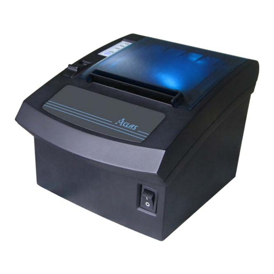
3 ACCESSORIES Adapter PC Disk User manual 4 GET TO KNOW THE PRINTER The switch to open the upper cover Power switch Power indicator light To prompt error To prompt the paper is run out Press this key to advance paper... - Page 6 INTERFACE: Connect to charger Connect to drawer RS232 Port [Model: PP7X3] Connect to charger RS232 Port Connect to drawer [Model: PP7XW2] Connect to charger Connect to drawer RS232 port [Model: PP7XW4] Connect to drawer Connect to charger USB port [Model: PPXU]...
- Page 7 Connect to drawer Connect to charger Parallel port [Model: PP7XD] Ethernet port Connect to charger Connect to drawer [Model: PP7XE] Connect to charger Connect to drawer RS232 Port [Model: PP7XWB]...
-
Page 8: Drawer Port Definition
5 DRAWER PORT DEFINITION The drawer port definition is similar to EPSON. The definition of 6PIN port is as follows: DRAWER DRAWER1# DRAWER_SW# P+24V DRAWER2# PHONE6P6C 102/2KV/DIP The definition of 4PIN port (Pinnacle self-defined) is as follows: DRAWER P+24V DRAWER_SW# DRAWER1 DRAWER2# PHONE4C... -
Page 9: Installation And Maintenance
6 INSTALLATION AND MAINTENANCE Paper Installation Paper roll diemnsion: Unit: mm Φ80 Φ80 Note: Bad quality thermal paper may quickly damage the thermal printer head, please use high quality thermal paper. (Bad quality thermal paper: roughness paper surface may quickly wear the pinter head; bad sensetive result in selecting ‘dark’... - Page 10 The alignment line 3. Let the paper parallel with the alignment line. 4. Pull out the leading age of paper and close the printer cover. 5. Tear off the spear paper and finish paper replacing.
-
Page 11: Print Test Page
Print Test Page Press key ‘Feed’ and hold it, and then power on the machine at the same time, it will print a piece of Test Page. The information of this Test Page includes the printer’s model, version, IP address (Ethernet port), ID and the default setting of the dip switch when leave factory. -
Page 12: Communication Board Replacement
Communication Board Replacement Note: Make sure that PP7X is powered off when you are changing the communication board. Power off PP7X for more than 10s, then the communication board can be replaced. Use the cross screwdriver unscrew these two screws. - Page 13 You can change the following communication boards according to your needs. And after replacement, please refer to the corresponding chapter according to the model. 433MHz wireless port module RS232 port module [Model: PP7XW4] [Model: PP7X3] P-tooth wireless USB port module communication port module [Model: PP7XU] [Model: PP7XW2]...
-
Page 14: Model: Pp7Xu
7 MODEL: PP7XU 7.1 Printer Driver Installation Connect the PP7X to PC. Click ‘Aclas printer.exe’ on the CD-disk, which is packed along with your computer. Install the printer driver as follows: Click ‘Next’ Click ‘Next’ Click ‘Next’... - Page 15 Click ‘Browse’ to select the destination location. Click ‘Next’ Here shows destination location. Click ‘Install’...
- Page 16 Choose this item Click ‘Next’ 选择如第 3.2 章,计算机 自动识别的端口 Note: If it is USB printer, please tick the box and click“NEXT”.If not, please directly click “NEXT”. Click ‘Next’...
- Page 17 Click ‘Finish’ to finish USB driver installation. Click‘Install’...
- Page 18 Click ‘Finish’ Finally, click ‘Finish’ to finish printer driver installation.
-
Page 19: How To Know The Connecting Port
7.2 How to Know the Connecting Port After you install USB driver, restart computer, and connect the PP7X to the computer. Then, you can follow steps below to know which port is connected. Right click ‘My Computer’ icon on the desktop, and choose ‘Manage’: Choose ‘Manage’... - Page 20 ① Select the connecting port ② Click it.
-
Page 21: Software Description
7.3 Software Description In the disk, you can find the software ‘PP7_en.exe’in the file ‘PC-SW’, double click to open it. Here, you can use the software to update program and download data. Connect PP7X to PC. Choose the correct port Update program... -
Page 22: Model: Pp7Xw4/Pp7Xw2
PP7XW2 is up to 10m without obstacle PP7X printers of this model are able to communicate with PC by two ways, via 433MHz Base Station or 2.4G Dongle. If you use 433MHz Base Station, please refer to Chapter 8.1; if use 2.4G Dongle, please refer to Chapter 8.2. - Page 23 If choose ‘Add IP Address To List’ to add printer, please input the new added printer’s ‘IP address’ and ‘comments’, and click ‘add’; if you need to resetting, click ‘Reset’. If you choose ‘Remove IP Address From List’, please input the new added printer’s IP address or comments, and click ‘Remove’;...
-
Page 24: Wireless 433 Usb Dongle/2.4G
Wireless 433 USB Dongle/2.4G 8.2.1 USB Dongle Driver Installation Before you install printer driver, you need to install the USB dongle driver first. Insert the USB dongle into PC. Double-click file Setup.exe, pop-up this window: Click this button to install. Here shows you the installation result. - Page 25 Choose ‘Device Manager’ Here connecting port.
-
Page 26: Printer Driver Installation
Connect the PP7X to PC. Click ‘Aclas printer.exe’ on the CD-disk, which is packed along with your computer. And then install the printer driver, please refer to chapter 7.1 for details, and choose the printer port as the connecting port shows in Chapter 8.2 when you install the driver. -
Page 27: Software Description
Software Description 1. Dongle Parameter Setting In the disk, you can find the file ‘DownloadDongle.exe’, double click to open it. Choose‘Hard’ Click this button to download setting. Local IP: the IP of 433 dongle. Target Dongle IP: the wireless IP address of PP7HW4. Stream CTRL: stream control, if the transmitting data is over 255byte, please choose ‘Hard’. - Page 28 In the disk, you can find the software ‘PP7_en.exe’ in the file ‘PC-SW’, double click to open it. Here, you can use the software to update program and download data. Connect PP7X to PC. Choose the correct port and Update program...
-
Page 29: Model: Pp7Xe
9 MODEL: PP7XE 9.1 Printer Driver Installation Note: If you want to use driver printing to realize many PC to communicate with many PP7X printer, please contact our company. Connect the PP7X to PC. Click ‘Aclas printer.exe’ on the CD-disk, which is packed along with your computer. - Page 30 Click ‘Next’ Input the printer IP address.
- Page 31 Choose device type, we suggest that you choose the standard type. Click ‘Next’ Click‘Finish’...
- Page 32 Click it...
-
Page 33: Software Description
9.2 Software Description In the disk, you can find the software ‘PP7_en.exe’ in the file folder ‘PC-SW’, double click to open it. Here, you can use the software to update program and download data. Choose TCP/IP Input the IP address Update program Download font Download parameter... -
Page 34: Model: Pp7Xd
10 MODEL: PP7XD 10.1 How to Know the Connecting Port After you connect the PP7X to the computer, then, you can follow the steps below to know which port is connected. Right click ‘My Computer’ icon on the desktop, and choose ‘Manage’: Choose ‘Manage’... -
Page 35: Printer Driver Installation
10.2 Printer Driver Installation Connect the PP7X to PC. Click ‘Aclas printer.exe’ on the CD-disk, which is packed along with your computer. And then install the printer driver, please refer to chapter 7.1 for details, and choose the printer port as the connecting port shows in Chapter 10.1 when you are install the driver. -
Page 36: Model: Pp7X3
11 MODEL: PP7X3 11.1 How to Know the Connecting Port Connect the PP7X to the computer. Then, you can follow the steps below to know which port is connected. Right click ‘My Computer’ icon on the desktop, and choose ‘Manage’: Choose ‘Manage’... -
Page 37: Software Description
In the disk, you can find the software ‘PP7_en.exe’ in the file folder ‘PC-SW’, double click to open it. Here, you can use the software to update program and download data. Connect PP7X to PC. Update program Choose the correct port and... -
Page 38: Model: Pp7Xwb
12 MODEL: PP7XWB The communication distance of PP7XWB is up to 10m without obstacle. 12.1 BT Driver Installation Method 1: This method is suitable for windows XP/VISTA OS. In the package, you can find a BT dongle. If you will connect the PP8X printer to the PC, insert this dongle into the USB port of PC. The lower right corner of screen will show the icon , double click it. - Page 39 Select this item Click ‘Next’...
- Page 40 Choose the BT device that you want to add. Click ‘Next’ Choose this item Set password here Click ‘Next’...
- Page 41 Installing device automatically Here shows the connecting port is COM3. Click ‘Finish’...
- Page 42 Method 2: This method is suitable for windows 98/2000/XP/VISTA OS If your operating system is windows 98 or windows 2000, you must install the BT driver first. And if your operating system is window XP or VISTA, the system has the driver itself, no need to install it again. If the 5M limit appeared during installing, please download the genuine driver in this address: http://www.bluesoleil.com/download/ 1.
- Page 43 Click ‘Next’ Click ‘Install’...
- Page 44 Click ‘Finish’...
- Page 45 After installing the BT driver, you need to match the BT. Insert the BT dongle into USB port of PC, double click the icon Note: if the icon is gray, right click the icon at the right bottom of the window, choose the item ‘Turn on Bluetooth’.
- Page 46 Double click it. Double click it to search.
- Page 47 Double click it. Input the passkey ‘0000’ to create paired relationship.
-
Page 48: How To Know The Connecting Port
Here you can see the bluetooth serial port is COM8. 12.2 How to Know the Connecting Port After installing the driver, you can follow the steps below to know which port is connected. Double click the icon Here shows the BT device you have installed... -
Page 49: Printer Driver Installation
12.3 Printer Driver Installation Connect the PP7X to PC. Click ‘Aclas printer.exe’ on the CD-disk, which is packed along with your computer. And then install the printer driver, please refer to chapter 7.1 for details, and choose the printer port as the... -
Page 50: Software Description
In the disk, you can find the software ‘PP7_en.exe’ in the file ‘PC-SW’, double click to open it. Here, you can use the software to update program and download data. Connect PP7X to PC. Choose RS232 Input the BT name. -
Page 51: Dip Switch
13 DIP SWITCH The communication port module is with dip switch, please refer to the picture below: The Dip Switch There are 8 switches altogether. Some of the printer’s function or parameter can be set via adjust SW-1~ SW-8. the table below is the default setting when leave factory. SW-1 SW-2 SW-3... - Page 52 Note: 1. Parallel port, Ethernet, USB, 2.4G P-tooth, and 433MHz wireless, the switch of these communication boards are ON, except SW-5 is OFF; 2. BT, P8, P6, and D9, the switch of these communication boards are ON, except SW-5, SW-7, and SW-8 are set as OFF;...
-
Page 53: Commands
14 COMMANDS The command explanations include the following parts: 1) Name and the general description of the command’s function---This is the first part for the command description; it presents the command’s ASCII code format and general description of its function. 2)... - Page 54 29 33 1D 21 Select character size Specify absolute position for character vertical direction 29 36 1D 24 in page mode 29 76 1D 4C Set left margin Specify relative position for character vertical direction 29 92 1D 5C in page mode GS P 29 80 1D 50...
- Page 55 Print and carriage return Format: ASCII Decimal Note: 1. Set the print position to the beginning of the line. 2. Print characters with LF command. print data in page mode ESC FF Format: ASCⅡ Decimal Description: Prints all buffered data in the print area collectively in page mode. Note: ∗...
- Page 56 Reference: ESC $, GS P Select standard mode ESC S Format: ASCⅡ Decimal Description: Switches from page mode to standard mode. Note: ∗ Valid only when input by page mode. ∗ All buffer data in page mode is deleted. ∗ Sets the print position to the beginning of the next line after execution. ∗...
- Page 57 Note: ∗ Executes only a printer internal flag operation when this command is input in standard mode. The command does not affect printing in standard mode. ∗ The character expansion starting point is in the print region specified by ESC W (Set print region in page mode).
- Page 58 Turn upside-down printing mode on/off ESC { Format: ASCⅡ Decimal Range: 0≤n≤255 ESC { n turns upside-down printing mode on or off. When the LSB (least significant bit) of n is 1, upside-down printing mode is turned on; when it is 0, upside-down printing mode is turned off. The default setting is n=0.
- Page 59 Set horizontal tab positions ESC D Format: ASCⅡ n1 … nk NUL Decimal n1 … nk 00 n1 … nk 0 Range: 1≤n≤255 0≤k≤32 Description: ESC D n1 … nk NUL sets a horizontal tab position to n columns from the beginning of a line, with k indication the total number of horizontal tab positions to be set.
- Page 60 unit set by GS P is used. When page mode is selected, the vertical or horizontal motion unit set by GS P is used fro the print direction set by ESC T. Note: ∗ In standard mode, the basic calculated pitch (y) for the vertical direction is used. ∗...
- Page 61 Set absolute print position ESC $ Format: ASCⅡ $ Decimal Range: 0≤nL≤255 0≤nH≤255 Description: Specifies the next printing starting position using an absolute position based on the left margin position. The next printing starting position is the position specified by [(nL+nH×256) × basic calculated pitch] from the left margin position.
- Page 62 ∗ If the horizontal direction length or vertical direction length is 0, the command is stopped and normal printing commences from subsequent data. ∗ The character expansion starting point is the point specified by selecting the character printing direction (ESC T) in page mode in the print region.
- Page 63 Select peripheral device ESC = n Format: ASCII Decimal Range: 0≤n≤255 ESC = n selects the device to which the host computer sends data, based on the value of n as follows: Off/On Decimal Function Printer disabled Printer enabled Undefined When the LSB (least significant bit) of n is 1, the printer is enabled;...
- Page 64 transmitting the paper sensor status. The status to be transmitted is shown in the table below. Off/On Decimal Status Paper roll near-end sensor: paper adequate. Paper roll near-end sensor: paper near end. Paper roll end sensor: paper present. (0C) (12) Paper roll end sensor: paper not present.
- Page 65 Printer no paper No error Error Fixed to Off n=3: transmit error state; Off/On Decimal Function Fixed to Off Fixed to On Undefined - - Cut no error Cut error Fixed to On No beyond retrieve error Beyond retrieve error Printer temperature voltage...
- Page 66 Double-width mode selected. Double-height mode not selected. Double-height mode selected. Undefined. Underline not selected. Underline selected. Set Chinese character space amount FS S n1 n2 Format: ASCII n1 n2 Decimal n1 n2 n1 n2 Range: 0≤n1≤255, 0≤n2≤255 Initial value: n1=0, n2=0 Description: 1.
- Page 67 ② m =65,66, 0 ≤n ≤255 Paper-cut Paper-cut mode 0, 48 Full-cut 1, 49 Partial-cut 65,66 Feed paper ([n* (lengthways moving unit ) inch]) and partial-cut ● m = 0, 48, 1, 49, cutting paper directly. ● m= 65, 66, feeding paper [the distance between printing position and the paper cutter + n*(lengthways moving unit)], and then cutting paper.
- Page 68 Note: ∗ This command is effective for all characters (ANK and Chinese characters), excluding HRI characters. ∗ If the vertical and horizontal magnification ratios are outside the defined range, this command is ignored. ∗ In standard mode, the vertical direction is the paper feed direction; the horizontal direction traverses the paper feed direction.
- Page 69 Description: 1. nL and nH set the specified left margin. 2. The left margin is [(nL + nH x 256) x basic calculated pitch] Note: ∗ This command is effective only when input at the top of the line when standard mode is being used. ∗...
- Page 70 Set basic calculated pitch GS P x y Format: ASCII GS P 1D 50 Decimal 29 80 Range: 0≤x≤255, 0≤y≤255 Initial value: x = 180, y = 360: EPSON targeted model print head 180 DPI x = 203, y = 203: EPSON targeted model print head 203 DPI Description: Sets the horizontal basic calculated pitch to approximately 25.4/xmm [(1/x) inch], and the vertical basic calculated pitch to approximately 25.4/ymm [(1/y) inch].
- Page 71 Set bar code height GS h n Format: ASCII Decimal Range: 1≤n≤255 GS h n selects the height of a bar code. n specifies the number of dots in the vertical direction. One dot corresponds to 1/180 inch. The default setting is n=162. Program Example PRINT #1,CHR$(&H1D);"h";CHR$(50);Set height to 50 PRINT #1,CHR$(&H1D);"k";CHR$(2);Print bar code...
- Page 72 Set bar code width GS w n Format: ASCII Decimal Range: 2≤n≤6 GS w n selects the horizontal size of a bar code. n specifies the bar code width as shown below. The multilevel bar codes are UPC-A, UPC-E, JAN13 (EAN13), JAN8 (EAN8), CODE93, and CODE128. The binary level bar codes are CODE39, ITF, and CODABAR.
- Page 73 Print bar code GS k m d1 ... dk NUL GS k m n d1 ... dn Format: m d1 ... dk NUL ①ASCII m d1 ... dk 00 Decimal m d1 ... dk 0 m n d1 ... dn ②ASCII m n d1 ...
- Page 74 subsequent data. ∗ If the horizontal width of the bar code exceeds the print region of one line, the paper is fed without printing the bar code. ∗ Executes a paper feed for the height of the bar code (including HRI characters when HRI character printing is specified) regardless of the line feed amount using the following commands.
-
Page 75: Command Sample (Hex Command)
15 COMMAND SAMPLE (hex command) 1d 68 64 1d 6b 02 34 39 36 35 39 35 37 30 37 33 37 39 00 0a //print a barcode width 1, height 100 1d 77 02 1d 6b 02 34 39 36 35 39 35 37 30 37 33 37 39 00 0a // print a barcode width 2, height 100 1d 77 02 1d 6b 02 32 32 30 30 30 30 32 30 30 30 35 30 35 00 0a // print EAN-13 barcode... - Page 76 DPP701ENV0-12...
Need help?
Do you have a question about the PP7X Series and is the answer not in the manual?
Questions and answers