Lenovo ThinkStation Hardware Maintenance Manual
Lenovo thinkstation machine types: 4262, 4263, 4264, 4265, 4266, 4269, 4271, and 4272
Hide thumbs
Also See for ThinkStation:
- Hardware maintenance manual (304 pages) ,
- User manual (102 pages) ,
- Product overview (9 pages)

Related Manuals for Lenovo ThinkStation


Summary of Contents for Lenovo ThinkStation
- Page 1 ThinkStation Hardware Maintenance Manual Machine Types: 4262, 4263, 4264, 4265, 4266, 4269, 4271, and 4272...
- Page 3 ThinkStation Hardware Maintenance Manual Machine Types: 4262, 4263, 4264, 4265, 4266, 4269, 4271, and 4272...
- Page 4 3 and Appendix A “Notices” on page 235. Seventh Edition (February 2012) © Copyright Lenovo 2010, 2012. LIMITED AND RESTRICTED RIGHTS NOTICE: If data or software are delivered pursuant a General Services Administration “GSA” contract, use, reproduction, or disclosure is subject to restrictions set forth in Contract No.
-
Page 5: Table Of Contents
SimpleTap ....Configuring the Marvell BIOS Setup to enable Lenovo Welcome....SATA/SAS RAID 0, 1, or 5 functionality . . . -
Page 6: Table Of Contents
Windows Vista Business 32 Recovery CD . . Windows Vista Business 64 Recovery CD . . Windows 7 Professional 64 (SP1) Recovery CD ....ThinkStation Hardware Maintenance Manual... -
Page 7: Chapter 1. About This Manual
This manual contains service and reference information for ThinkStation™ computers listed on the front cover. It is intended only for trained servicers who are familiar with Lenovo® computer products. Before servicing a Lenovo product, be sure to read the Safety Information in Chapter 2 “Safety information” on page 3. - Page 8 Lenovo plans to transition to RoHS compliance well before the implementation date and expects its suppliers to be ready to support Lenovo's requirements and schedule in the EU. Products sold in 2005 will contain some RoHS compliant FRUs. The following statement pertains to these products and any product Lenovo produces containing RoHS compliant parts.
-
Page 9: Chapter 2. Safety Information
Observe the following rules when working on electrical equipment. © Copyright Lenovo 2010, 2012... - Page 10 (This practice ensures correct grounding of the units.) • If an electrical accident occurs: – Use caution; do not become a victim yourself. – Switch off power. – Send another person to get medical aid. ThinkStation Hardware Maintenance Manual...
-
Page 11: Voltage-Selection Switch
Voltage-selection switch Some computers are equipped with a voltage-selection switch located near the power-cord connection point on the computer. If your computer has a voltage-selection switch, ensure that you set the switch to match the voltage available at your electrical outlet. Setting the voltage-selection switch incorrectly can cause permanent damage to the computer. -
Page 12: Handling Electrostatic Discharge-Sensitive Devices
Safety notices (multi-lingual translations) The caution and danger safety notices in this section are provided in the following languages: • English • Arabic • Brazilian/Portuguese • Chinese (simplified) • Chinese (traditional) ThinkStation Hardware Maintenance Manual... - Page 13 • French • German • Hebrew • Italian • Korean • Spanish DANGER Electrical current from power, telephone and communication cables is hazardous. To avoid a shock hazard: • Do not connect or disconnect any cables or perform installation, maintenance, or reconfiguration of this product during an electrical storm.
- Page 14 The device also might have more than one power cord. To remove all electrical current from the device, ensure that all power cords are disconnected from the power source. ThinkStation Hardware Maintenance Manual...
- Page 15 Chapter 2 Safety information...
- Page 16 ≥18 kg (37 lbs) ≥32 kg (70.5 lbs) ≥55 kg (121.2 lbs) PERIGO ThinkStation Hardware Maintenance Manual...
- Page 17 A corrente elétrica proveniente de cabos de alimentação, de telefone e de comunicações é perigosa. Para evitar risco de choque elétrico: • Não conecte nem desconecte nenhum cabo ou execute instalação, manutenção ou reconfiguração deste produto durante uma tempestade com raios. •...
- Page 18 O dispositivo também pode ter mais de um cabo de alimentação. Para remover toda a corrente elétrica do dispositivo, assegure que todos os cabos de alimentação estejam desconectados da fonte de alimentação. ThinkStation Hardware Maintenance Manual...
- Page 19 Chapter 2 Safety information...
- Page 20 ThinkStation Hardware Maintenance Manual...
- Page 21 Chapter 2 Safety information...
- Page 22 (sauf instruction contraire mentionnée dans les procédures d'installation et de configuration). • Lorsque vous installez, que vous déplacez, ou que vous manipulez le présent produit ou des périphériques qui lui sont raccordés, reportez-vous aux instructions ci-dessous pour connecter et déconnecter les différents cordons. ThinkStation Hardware Maintenance Manual...
- Page 23 Connexion Déconnexion 1. Mettez les unités HORS TENSION. 1. Mettez les unités HORS TENSION. 2. Commencez par brancher tous les cordons sur les 2. Débranchez les cordons d'alimentation des prises. unités. 3. Débranchez les câbles d'interface des connecteurs. 3. Branchez les câbles d'interface sur des connecteurs. 4.
- Page 24 Schutzkontakt anschließen. • Die Signalkabel nach Möglichkeit einhändig anschließen oder lösen, um einen Stromschlag durch Berühren von Oberflächen mit unterschiedlichem elektrischem Potenzial zu vermeiden. • Geräte niemals einschalten, wenn Hinweise auf Feuer, Wasser oder Gebäudeschäden vorliegen. ThinkStation Hardware Maintenance Manual...
- Page 25 • Die Verbindung zu den angeschlossenen Netzkabeln, Telekommunikationssystemen, Netzwerken und Modems ist vor dem Öffnen des Gehäuses zu unterbrechen, sofern in den Installations- und Konfigurationsprozeduren keine anders lautenden Anweisungen enthalten sind. • Zum Installieren, Transportieren und Öffnen der Abdeckungen des Computers oder der angeschlossenen Einheiten die Kabel gemäß...
- Page 26 Mit dem Netzschalter an der Einheit und am Netzteil wird die Stromversorgung für die Einheit nicht unterbrochen. Die Einheit kann auch mit mehreren Netzkabeln ausgestattet sein. Um die Stromversorgung für die Einheit vollständig zu unterbrechen, müssen alle zum Gerät führenden Netzkabel vom Netz getrennt werden. ThinkStation Hardware Maintenance Manual...
- Page 27 Chapter 2 Safety information...
- Page 28 • Collegare tutti i fili elettrici a una presa di alimentazione correttamente cablata e dotata di messa a terra. • Collegare alle prese elettriche appropriate tutte le apparecchiature che verranno utilizzate per questo prodotto. ThinkStation Hardware Maintenance Manual...
- Page 29 • Se possibile, utilizzare solo una mano per collegare o scollegare i cavi di segnale. • Non accendere assolutamente apparecchiature in presenza di incendi, perdite d'acqua o danno strutturale. • Scollegare i cavi di alimentazione, i sistemi di telecomunicazione, le reti e il modem prima di aprire i coperchi del dispositivo, salvo istruzioni contrarie relative alle procedure di installazione e configurazione.
- Page 30 Il pulsante di controllo dell'alimentazione presente sull'unità e l'interruttore dell'alimentatore non disattivano l'alimentazione corrente fornita all'unità. E' possibile che l'unità disponga di più cavi di alimentazione. Per disattivare l'alimentazione dall'unità, accertarsi che tutti i cavi di alimentazione siano scollegati dalla fonte di alimentazione. ThinkStation Hardware Maintenance Manual...
- Page 31 Chapter 2 Safety information...
- Page 32 • Cualquier equipo que se conecte a este producto también debe conectarse a tomas de corriente debidamente cableadas. • Siempre que sea posible, utilice una sola mano para conectar o desconectar los cables de señal. • No encienda nunca un equipo cuando hay señales de fuego, agua o daños estructurales. ThinkStation Hardware Maintenance Manual...
- Page 33 • Desconecte los cables de alimentación, los sistemas de telecomunicaciones, las redes y los módems conectados antes de abrir las cubiertas de los dispositivos, a menos que se indique lo contrario en los procedimientos de instalación y configuración. • Conecte y desconecte los cables, como se describe en la tabla siguiente, cuando instale, mueva o abra las cubiertas de este producto o de los dispositivos conectados.
- Page 34 Además, el dispositivo podría tener más de un cable de alimentación. Para suprimir toda la corriente eléctrica del dispositivo, asegúrese de que todos los cables de alimentación estén desconectados de la toma de corriente. ThinkStation Hardware Maintenance Manual...
-
Page 35: Chapter 3. General Information
The Lenovo Solution Center program enables you to troubleshoot and resolve computer problems. It combines diagnostic tests, system information collection, security status, and support information, along with hints and tips for maximum system performance. See “Lenovo Solution Center” on page 33 for detailed information. -
Page 36: Additional Information Resources
– Low range: Minimum: 100 V ac Maximum: 127 V ac Input frequency range: 50 to 60 Hz – High range: Minimum: 200 V ac Maximum: 240 V ac Input frequency range: 50 to 60 Hz ThinkStation Hardware Maintenance Manual... -
Page 37: Chapter 4. General Checkout
Service Support and Engineering functions. • Machine type and model • Processor or hard disk drive upgrades • Failure symptom – Do diagnostics indicate a failure? – What, when, where, single, or multiple systems? – Is the failure repeatable? © Copyright Lenovo 2010, 2012... - Page 38 6. Have the same diagnostic diskettes (version) 7. Have the same configuration options set in the system 8. Have the same setup for operating-system-controlled files Comparing the configuration and software set-up between “working and non-working” systems will often lead to problem resolution. ThinkStation Hardware Maintenance Manual...
-
Page 39: Chapter 5. Diagnostics
3. If you are unable to isolate and repair the problem yourself after running the programs, save and print the log files created by the programs. You will need the log files when you speak to a Lenovo technical support representative. -
Page 40: Pc-Doctor For Dos
Note: If you are unable to isolate and repair the problem yourself after running the program, save and print the log files created by the program. You will need the log files when you speak to a Lenovo technical support representative. -
Page 41: Test Results
• Using the cursor movement keys, highlight Run Normal Test or Run Quick Test from the Diagnostics menu and then press Enter. This automatically runs a pre-defined group of tests from each test category. Run Normal Test runs a more extensive set of tests than Run Quick Test does and takes longer to complete. - Page 42 To view details of a failure or to view a list of test results, use the following procedure from any test category screen: 1. Press F3 to activate the log file. 2. Press F3 again to save the file to diskette or press F2 to print the file. ThinkStation Hardware Maintenance Manual...
-
Page 43: Program
• Set Administrator Password • Set User Password You do not have to set a password to use your computer. However, using a password improves computing security. If you decide to set a password, read the following sections. © Copyright Lenovo 2010, 2012... -
Page 44: Password Considerations
Note: A password can be any combination of up to 12 (1 to 12) alphabetic and numeric characters. For more information, see “Password considerations” on page 38. Enabling or disabling a device This section provides instructions on how to enable or disable user access to a device. ThinkStation Hardware Maintenance Manual... -
Page 45: Selecting A Startup Device
USB Support Use this option to enable or disable USB connectors. ICH SATA When this feature is set to Disabled, any optical drives or eSATA devices are disabled and will not be displayed in the system configuration. Marvell SATA/SAS controller When this feature is set to Disabled, all internal hard disk drives are disabled and will not be displayed in the system configuration. -
Page 46: Advanced Settings
• If you do not want to save the new settings, select Exit ® Exit the Setup Utility without saving. • If you want to return to the default settings, press F9 or select Exit ® Load Default Settings. ThinkStation Hardware Maintenance Manual... -
Page 47: Chapter 7. Configuring Raid
2. From the Setup Utility program main menu, select Devices ® IDE Drives Setup and press Enter. 3. Select SATA RAID Enable and press Enter. 4. Select Enabled and press Enter. 5. Press F10 to save the new settings and exit the Setup Utility program. © Copyright Lenovo 2010, 2012... -
Page 48: Creating Raid Volumes
Note: Your computer must have either all SATA hard disk drives or all SAS hard disk drives installed. However, be sure that you do not install both the SATA and SAS hard disk drives into the same computer. ThinkStation Hardware Maintenance Manual... -
Page 49: Installing Sata Or Sas Hard Disk Drives
Installing SATA or SAS hard disk drives Your computer must have the minimum number of SATA or SAS hard disk drives installed for the supported level of RAID below: • RAID Level 0 – Striped disk array – Two hard disk drives minimum –... -
Page 50: Optional Hot Spare Hard Disk Drive
4. Use the arrow keys and the Enter key to select the array you want to delete from the list. 5. Use the arrow keys to select Next and press Enter. 6. Press Y when prompted to complete the deletion. ThinkStation Hardware Maintenance Manual... -
Page 51: Chapter 8. Symptom-To-Fru Index
• On/Off switch connector • On/Off switch power supply connector • System board power supply connectors • Microprocessor(s) connection Check the power cord for continuity. Power cord Check the turn on switch for continuity. Turn on switch © Copyright Lenovo 2010, 2012... -
Page 52: Diagnostic Error Codes
Information only Restart the test, if necessary 000-195-XXX BIOS Test aborted by user 000-196-XXX BIOS test halt, error threshold exceeded 1. Press F3 to review the log file. 2. Restart the test to reset the log file. ThinkStation Hardware Maintenance Manual... - Page 53 Diagnostic Error Code FRU/Action 1. Make sure the component that is called out is 000-197-XXX BIOS test warning connected and/or enabled. See Chapter 6 “Using the Setup Utility program” on page 37. 2. Re-run test. 3. Replace the component that is called out in warning statement 4.
- Page 54 2. System board 001-270-XXX System IRQ3 failure 1. Device on IRQ3 2. System board 001-271-XXX System IRQ4 failure 1. Device on IRQ4 2. System board 001-272-XXX System IRQ5 failure 1. Device on IRQ5 2. System board ThinkStation Hardware Maintenance Manual...
- Page 55 Diagnostic Error Code FRU/Action 001-273-XXX System IRQ6 (diskette drive) failure 1. Diskette Cable 2. Diskette drive 3. System board 001-274-XXX System IRQ7 failure 1. Device on IRQ7 2. System board 001-275-XXX System IRQ8 failure 1. Device on IRQ8 2. System board 001-276-XXX System IRQ9 failure 1.
- Page 56 3. Go to “Undetermined problems” on page 67. 005-199-XXX Video test failed, cause unknown 1. Go to “Undetermined problems” on page 67. 2. Flash the system and re-test. See “Updating (flashing) the BIOS” on page 229. 3. Replace component under function test. ThinkStation Hardware Maintenance Manual...
- Page 57 Diagnostic Error Code FRU/Action 005-2XX-XXX 005-3XX-XXX Video subsystem error 1. Video card, if installed 2. System board 006-000-XXX Diskette interface Test Passed No action 006-0XX-XXX Diskette interface error 1. Diskette drive Cable 2. Diskette drive 3. System board 006-195-XXX Diskette interface Test aborted by user Information only Restart the test, if necessary 006-196-XXX Diskette interface test halt, error threshold 1.
- Page 58 014-195-XXX Parallel port Test aborted by user Information only Restart the test, if necessary. 014-196-XXX Parallel port test halt, error threshold 1. Press F3 to review the log file. exceeded 2. Restart the test to reset the log file. ThinkStation Hardware Maintenance Manual...
- Page 59 Diagnostic Error Code FRU/Action 014-197-XXX Parallel port test warning 1. Make sure the component that is called out is connected and/or enabled. See Chapter 6 “Using the Setup Utility program” on page 37. 2. Re-run test. 3. Replace the component that is called out in warning statement.
- Page 60 3. Go to “Undetermined problems” on page 67. 018-199-XXX PCI Card test failed, cause unknown 1. Go to “Undetermined problems” on page 67. 2. Flash the system and re-test. See “Updating (flashing) the BIOS” on page 229. 3. Replace component under function test. ThinkStation Hardware Maintenance Manual...
- Page 61 Diagnostic Error Code FRU/Action 018-250-XXX PCI Card Services error 1. PCI card 2. Riser card, if installed. 3. System board 020-000-XXX PCI Interface Test Passed No action 020-0XX-XXX PCI Interface error 1. PCI card 2. Riser card, if installed. 3. System board 020-195-XXX PCI Test aborted by user Information only Restart the test, if necessary 020-196-XXX PCI test halt, error threshold exceeded...
- Page 62 030-03X-XXX 030-04X-XXX SCSI interface error 1. SCSI signal cable 2. Check power supply 3. SCSI device 4. SCSI adapter card, if installed. 5. System board 030-195-XXX SCSI interface Test aborted by user Information only Restart the test, if necessary. ThinkStation Hardware Maintenance Manual...
- Page 63 Diagnostic Error Code FRU/Action 030-196-XXX SCSI interface test halt, error threshold 1. Press F3 to review the log file. exceeded 2. Restart the test to reset the log file. 030-197-XXX SCSI interface test warning 1. Make sure the component that is called out is connected and/or enabled.
- Page 64 080-195-XXX Game Port interface Test aborted by user Information only Restart the test, if necessary. 1. Press F3 to review the log file. 080-196-XXX Game Port interface test halt, error threshold exceeded 2. Restart the test to reset the log file. ThinkStation Hardware Maintenance Manual...
- Page 65 Diagnostic Error Code FRU/Action 1. Make sure the component that is called out is 080-197-XXX Game Port interface test warning connected and/or enabled. See Chapter 6 “Using the Setup Utility program” on page 37. 2. Re-run test. 3. Replace the component that is called out in warning statement.
- Page 66 See Chapter 6 “Using the Setup Utility program” on page 37. 2. Flash the system and re-test. See “Updating (flashing) the BIOS” on page 229. 3. Go to “Undetermined problems” on page 67. ThinkStation Hardware Maintenance Manual...
- Page 67 Diagnostic Error Code FRU/Action 170-199-XXX Voltage Sensor(s) test failed, cause unknown 1. See “Undetermined problems” on page 67. 2. Flash the system and re-test. See “Updating (flashing) the BIOS” on page 229. 3. Replace component under function test. 1. Power supply 170-250-XXX 170-251-XXX Voltage Sensor(s) Voltage limit error 2.
- Page 68 No action 302-000-XXX Mouse Test Passed No action 302-XXX-XXX Mouse error 1. Mouse 2. Check and test Keyboard. 3. System board 303-000-XXX Joystick Test Passed No action 303-XXX-XXX Joystick error Remove the Joystick and re-test the system. ThinkStation Hardware Maintenance Manual...
-
Page 69: Beep Symptoms
Diagnostic Error Code FRU/Action No action 305-000-XXX Monitor DDC Test Passed 305-250-XXX Monitor DDC self test failure 1. Run the Setup Utility program to enable DDC. 2. Cable 3. Monitor 4. Video card 5. System board 415-000-XXXModem Test Passed No action 415-XXX-XXX Modem error Remove the Modem and re-test the system. -
Page 70: Post Error Codes
This message displays during a full memory test, counting down the memory areas being tested. Memory test fail If POST detects an error during memory testing, additional information appears. This information gives specifics about the type and location of the memory error. ThinkStation Hardware Maintenance Manual... -
Page 71: Miscellaneous Error Messages
POST Error Message Description/Action Pressing the TAB key permits the user to toggle between Press TAB to show POST screen the default POST display screen and a custom POST display screen. Error: Non-System disk or disk error Replace and press The BIOS was unable to find a suitable boot device. - Page 72 Serial or parallel port device failure (adapter port) 1. External Device Self-Test OK? 2. External Device 3. Cable 4. Alternate Adapter 5. System Board 1. Keyboard Some or all keys on the keyboard do not work 2. Keyboard Cable 3. System Board ThinkStation Hardware Maintenance Manual...
-
Page 73: Undetermined Problems
Undetermined problems This section provides instructions on how to find out the failing devices or adapters. 1. Turn off the computer. 2. Remove or disconnect the following components (if installed) one at a time. a. External devices (modem, printer, or mouse) b. - Page 74 ThinkStation Hardware Maintenance Manual...
-
Page 75: Chapter 9. Replacing Frus
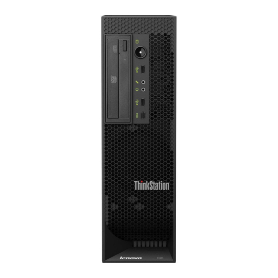
Figure 1. Front control and connector locations Hard disk drive activity indicator Headphone connector Power switch and power indicator USB connector USB connector IEEE 1394 connector (available on some models) Microphone connector Optical drive eject button © Copyright Lenovo 2010, 2012... -
Page 76: Locating Connectors On The Rear Of Your Computer
Figure 3 “Component locations” on page 71 shows the locations of the various components in your computer. To remove the computer cover and access the inside of the computer, see “Removing the computer cover” on page 74. ThinkStation Hardware Maintenance Manual... -
Page 77: Locating Parts And Connectors On The System Board
Figure 3. Component locations Microprocessor 1 Hard disk drive bay Memory modules Hard disk drives (3) Heat sink and fan assembly 2 System board Microprocessor 2 Power supply assembly Optical drive bracket PCI card Optical drive Heat sink and fan assembly 1 Internal Speaker Rear fan assemblies (2) Front fan assembly bracket... - Page 78 Auxiliary 12 V power connector Front USB connector Left rear fan connector Front IEEE 1394 connector CPU 1 12 V power connector Hard disk drive connectors (5) CPU 1 fan connector Microprocessor 1 Optical drive connectors (3) Battery ThinkStation Hardware Maintenance Manual...
- Page 79 Figure 5 “System board part and connector locations” on page 73 shows the locations of the parts and connectors on the other type of system board. Figure 5. System board part and connector locations CPU 1 memory slots (3) Clear CMOS (Complementary Metal Oxide Semiconductor) /Recovery jumper CPU 1 memory fan connector Thermal sensor connector...
-
Page 80: Removing The Computer Cover
Do not open your computer or attempt any repair before reading and understanding the “Important safety information” in the ThinkStation Safety and Warranty Guide that came with your computer. To obtain a copy of the ThinkStation Safety and Warranty Guide, go to: http://www.lenovo.com/support... -
Page 81: Removing And Reinstalling The Front Bezel
Do not open your computer or attempt any repair before reading and understanding the “Important safety information” in the ThinkStation Safety and Warranty Guide that came with your computer. To obtain a copy of the ThinkStation Safety and Warranty Guide, go to: http://www.lenovo.com/support... -
Page 82: Removing And Reinstalling The Pci Card Holder
Do not open your computer or attempt any repair before reading and understanding the “Important safety information” in the ThinkStation Safety and Warranty Guide that came with your computer. To obtain a copy of the ThinkStation Safety and Warranty Guide, go to: http://www.lenovo.com/support... - Page 83 Figure 8. Removing the PCI card holder 6. To reinstall the PCI card holder into the chassis, insert the two tabs into the corresponding holes in the chassis, and then pivot the PCI card holder downward until the front of the card holder snaps into position.
-
Page 84: Installing Or Replacing A Memory Module
Do not open your computer or attempt any repair before reading and understanding the “Important safety information” in the ThinkStation Safety and Warranty Guide that came with your computer. To obtain a copy of the ThinkStation Safety and Warranty Guide, go to: http://www.lenovo.com/support... - Page 85 • Always install DIMMs in the numerical order printed on the system board (DIMM1, DIMM2, DIMM3, and so on). Install memory modules into the blue memory slots first. • If your computer has only one CPU installed, be sure to install memory modules only in the memory slots adjacent to that CPU.
- Page 86 Figure 13. Removing a memory module Notes: a. If your computer has 12 memory slots on the system board, you might have to use more force to remove the memory modules installed in memory slots ThinkStation Hardware Maintenance Manual...
- Page 87 b. If your computer has six memory slots on the system board, you might have to use more force to remove the memory module installed in memory slot 8. Position the new memory module over the memory slot. Make sure that the notch on the memory module aligns correctly with the key in the memory slot.
-
Page 88: Installing Or Replacing A Pci Card
Do not open your computer or attempt any repair before reading and understanding the “Important safety information” in the ThinkStation Safety and Warranty Guide that came with your computer. To obtain a copy of the ThinkStation Safety and Warranty Guide, go to: http://www.lenovo.com/support... - Page 89 • Two PCI Express x16 card slots To install or replace a PCI card, do the following: 1. Remove all media from the drives and turn off all attached devices and the computer. Then, disconnect all power cords from electrical outlets and disconnect all cables that are connected to the computer. 2.
-
Page 90: Installing A New Hard Disk Drive
Do not open your computer or attempt any repair before reading and understanding the “Important safety information” in the ThinkStation Safety and Warranty Guide that came with your computer. To obtain a copy of the ThinkStation Safety and Warranty Guide, go to: http://www.lenovo.com/support... - Page 91 Figure 18. Installing a new hard disk drive into the bracket 7. Connect one end of the signal cable that comes with the new hard disk drive to the rear of the new hard disk drive. Note: The signal cable will be different depending on whether you are installing a SATA hard disk drive or a SAS hard disk drive.
- Page 92 Note: You might need to disconnect power cables for other hard disk drives installed in your computer and then rotate the air flow wall outward for easier access to the rear of the new hard disk drive. ThinkStation Hardware Maintenance Manual...
-
Page 93: Replacing A Hard Disk Drive
Do not open your computer or attempt any repair before reading and understanding the “Important safety information” in the ThinkStation Safety and Warranty Guide that came with your computer. To obtain a copy of the ThinkStation Safety and Warranty Guide, go to: http://www.lenovo.com/support... -
Page 94: Replacing The Optical Drive
Do not open your computer or attempt any repair before reading and understanding the “Important safety information” in the ThinkStation Safety and Warranty Guide that came with your computer. To obtain a copy of the ThinkStation Safety and Warranty Guide, go to: http://www.lenovo.com/support... - Page 95 4. Disconnect the signal cable and the power cable from the rear of the optical drive, press the blue release button as shown, and then slide the optical drive out of the computer. Figure 24. Removing the optical drive 5. Install the optical drive retainer on the side of the new optical drive.
-
Page 96: Replacing The Heat Sink And Fan Assembly
Do not open your computer or attempt any repair before reading and understanding the “Important safety information” in the ThinkStation Safety and Warranty Guide that came with your computer. To obtain a copy of the ThinkStation Safety and Warranty Guide, go to: http://www.lenovo.com/support... - Page 97 b. Pivot the optical drive bracket as shown in the following illustration and then remove it from the chassis. Go to 6 on page 91. Figure 27. Removing the optical drive bracket 6. Disconnect the heat sink and fan assembly cable from the system board. Note the cable location. 7.
- Page 98 71. 13. If you are replacing heat sink and fan assembly 2, reinstall the optical drive bracket into the chassis. 14. Reinstall the optical drive into the chassis. See “Replacing the optical drive” on page 88. ThinkStation Hardware Maintenance Manual...
-
Page 99: Replacing The Microprocessor
Do not open your computer or attempt any repair before reading and understanding the “Important safety information” in the ThinkStation Safety and Warranty Guide that came with your computer. To obtain a copy of the ThinkStation Safety and Warranty Guide, go to: http://www.lenovo.com/support... - Page 100 10. Lower the microprocessor straight down into the microprocessor socket of the system board. 11. Close the microprocessor retainer and clamp it with the small handle. 12. Reinstall the heat sink and fan assembly. See “Replacing the heat sink and fan assembly” on page 90. ThinkStation Hardware Maintenance Manual...
-
Page 101: Replacing The System Board
Do not open your computer or attempt any repair before reading and understanding the “Important safety information” in the ThinkStation Safety and Warranty Guide that came with your computer. To obtain a copy of the ThinkStation Safety and Warranty Guide, go to: http://www.lenovo.com/support... - Page 102 14. Remove the six screws that secure the system board to the chassis. Figure 29. Removing the six screws that secure the system board to the chassis 15. Carefully lift the failing system board out of the chassis. ThinkStation Hardware Maintenance Manual...
- Page 103 16. Position the new system board into the chassis so that the screw holes in the new system board are aligned with those in the chassis. Install the six screws that secure the system board to the chassis. 17. Reinstall the two memory chiller frames and the black cable clip by tightening the eight screws to secure them to the system board.
-
Page 104: Replacing The Battery
Do not open your computer or attempt any repair before reading and understanding the “Important safety information” in the ThinkStation Safety and Warranty Guide that came with your computer. To obtain a copy of the ThinkStation Safety and Warranty Guide, go to: http://www.lenovo.com/support. -
Page 105: Replacing The Power Supply Assembly
Do not open your computer or attempt any repair before reading and understanding the “Important safety information” in the ThinkStation Safety and Warranty Guide that came with your computer. To obtain a copy of the ThinkStation Safety and Warranty Guide, go to: http://www.lenovo.com/support. - Page 106 6. Remove the optical drive. See “Replacing the optical drive” on page 88. 7. Pivot the optical drive bracket as shown in the following illustration and then remove it from the chassis. Figure 30. Removing the optical drive bracket ThinkStation Hardware Maintenance Manual...
- Page 107 8. Position the computer upside down. 9. Remove the three screws that secure the side cover as shown in the following illustration. Figure 31. Removing the side cover screws 10. Remove the other six screws that secure the side cover as shown in the following illustration. Then, lift the side cover and remove it from the computer.
- Page 108 Remove the four screws at the rear of the chassis that secure the power supply assembly. c. Slide the power supply assembly toward the front of the computer and then lift it out of the chassis. ThinkStation Hardware Maintenance Manual...
- Page 109 Figure 33. Removing the power supply assembly 13. Install the new power supply assembly into the chassis, make sure the screw holes in the new power supply assembly align with those in the chassis. 14. Install the four screws at the rear of the chassis to secure the new power supply assembly in place. 15.
-
Page 110: Replacing The Front Fan Assembly
Replacing the front fan assembly Attention Do not open your computer or attempt any repair before reading and understanding the “Important safety information” in the ThinkStation Safety and Warranty Guide that came with your computer. To obtain a copy ThinkStation Hardware Maintenance Manual... - Page 111 ThinkStation Safety and Warranty Guide, go to: http://www.lenovo.com/support This section provides instructions on how to replace the front fan assembly. Note: Not all computers have the front fan assembly. To replace the front fan assembly, do the following: 1.
-
Page 112: Replacing The Rear Fan Assembly
Do not open your computer or attempt any repair before reading and understanding the “Important safety information” in the ThinkStation Safety and Warranty Guide that came with your computer. To obtain a copy of the ThinkStation Safety and Warranty Guide, go to: http://www.lenovo.com/support... - Page 113 To replace the rear fan assembly, do the following: 1. Remove all media from the drives and turn off all attached devices and the computer. Then, disconnect all power cords from electrical outlets and disconnect all cables that are connected to the computer. 2.
-
Page 114: Replacing The Internal Speaker
Do not open your computer or attempt any repair before reading and understanding the “Important safety information” in the ThinkStation Safety and Warranty Guide that came with your computer. To obtain a copy of the ThinkStation Safety and Warranty Guide, go to: http://www.lenovo.com/support. - Page 115 5. Remove the optical drive and the optical drive bracket. See “Replacing the optical drive” on page 88. 6. Locate the internal speaker connector on the system board. See “Locating parts and connectors on the system board” on page 71. 7.
-
Page 116: Completing The Parts Replacement
4. Position the computer cover on the chassis so that the rail guides on the bottom of the computer cover engage with the rails on the chassis. Then, close the computer cover to engage the cover-release button. ThinkStation Hardware Maintenance Manual... - Page 117 Setup Utility program. Refer to Chapter 6 “Using the Setup Utility program” on page 37. Note: In most areas of the world, Lenovo requires the return of the defective Customer Replaceable Unit (CRU). Information about this will come with the CRU or will come a few days after the CRU arrives.
- Page 118 ThinkStation Hardware Maintenance Manual...
-
Page 119: Chapter 10. Fru Lists
• MT 4269: all models • MT 4272: all models FRU, heat sink for microprocessor 1 - workstation microprocessors (130W) • MT 4266: all models 41R5730 • MT 4269: all models • MT 4272: all models © Copyright Lenovo 2010, 2012... - Page 120 L2, DDR3-800, 80W • MT 4262: CTO • MT 4263: 27A CTO • MT 4264: CTO 46R6632 • MT 4265: 48G 23H CTO • MT 4266: CTO • MT 4269: CTO • MT 4272: 22V 29V CTO ThinkStation Hardware Maintenance Manual...
- Page 121 Item # FRUs FRU # Microprocessor, Intel Xeon E5507 - Quad Core - 2.26GHz - 4.8 QPI DDR3-800-4MB 80W • MT 4262: CTO • MT 4263: 18G 25G 53C 54C 79U 79F 79S CTO 83C • MT 4264: CTO 71Y9031 •...
- Page 122 Microprocessor, Intel Xeon X5550 - 2.66GHz, Quad Core - 6.4 QPI, 8MB L2, DDR3-1333, Turbo, SMT, 95W • MT 4262: CTO • MT 4263: CTO • MT 4264: CTO 46R6638 • MT 4265: CTO • MT 4266: CTO • MT 4269: CTO • MT 4272: CTO ThinkStation Hardware Maintenance Manual...
- Page 123 Item # FRUs FRU # Microprocessor, Intel Xeon X5560 - 2.80GHz, Quad Core - 6.4 QPI, 8MB L2, DDR3-1333, Turbo, SMT, 95W • MT 4262: CTO • MT 4263: CTO • MT 4264: CTO 46R6639 • MT 4265: CTO • MT 4266: CTO •...
- Page 124 • MT 4262: CTO • MT 4263: CTO • MT 4264: CTO 03T8031 • MT 4265: CTO 1LG 2MG • MT 4266: CTO • MT 4269: 38A 43C 49Q CTO 58M • MT 4272: 11J CTO ThinkStation Hardware Maintenance Manual...
- Page 125 Item # FRUs FRU # Microprocessor, Intel Xeon E5607 - Quad Core - 2.26Ghz - 4.8 QPI, 8MB Cache, DDR3 - 1066, No HT, No Turbo, 80W • MT 4262: CTO • MT 4263: CTO A2U A2F A5J A9G B4U B4F B5J C3G •...
- Page 126 • MT 4265: 63G 13U 13F 13S 13L 13D 13Y 13M 13A 13Q 13T 13C 13B 13H 13V 13K 13R 13E 13J CTO 74J • MT 4266: CTO • MT 4269: 36A 37A 38A 39A 49Q CTO 62A 63A • MT 4272: 34Q CTO ThinkStation Hardware Maintenance Manual...
- Page 127 Item # FRUs FRU # Memory module, 2GB DDR3 ECC UDIMM PC3-10600 (1333MHz) • MT 4262: 11Q 14F CTO 14U • MT 4263: 13G 14G 15G 18G 19G 23G 24G 25G 67U 67F 67S 57G 61G 62G 63G 47C 48C 49C 52C 53C 54C 55C 56C 34A 34T 35A 35T 66K 66R 72U 72F 72S 72L 72D 72Y 72G 72M 72A 72Q 72T 72C 72B 72H 72V 72K 72R 72E 79U 79F 79S CTO 86M 87M 88M 89M 91M 84J 85J 83C 94A 95A 96C 97U 97F 97S 97P 97L 97D 97Y 97M 97A 97Q 97T...
- Page 128 Memory module, 1GB DDR3 ECC UDIMM PC3-8500 (1066MHz) • MT 4262: CTO • MT 4263: 11G CTO • MT 4264: CTO 53Y6195 • MT 4265: 11G 12G 13G 14G CTO • MT 4266: CTO • MT 4269: CTO • MT 4272: CTO ThinkStation Hardware Maintenance Manual...
- Page 129 Item # FRUs FRU # Memory module, 2GB DDR3 ECC UDIMM PC3-8500 (1066MHz) • MT 4262: CTO • MT 4263: CTO • MT 4264: CTO 53Y6197 • MT 4265: CTO • MT 4266: CTO • MT 4269: CTO • MT 4272: CTO Memory module, 1GB DDR3 1RX8 RDIMM PC3-10600 (1333MHz) •...
- Page 130 • MT 4266: all models • MT 4269: all models • MT 4272: all models FRU, heat sink for microprocessor 2- workstation microprocessors (130W) • MT 4266: all models 41R5732 • MT 4269: all models • MT 4272: all models ThinkStation Hardware Maintenance Manual...
- Page 131 Item # FRUs FRU # Optical drive, DVD-ROM Drive - 16x/48x (SATA) - DOS/Linux/XP/Vista/Windows 7 • MT 4262: CTO • MT 4263: 71U 71F 71S 71L 71D 71Y 71G 71M 71A 71Q 71T 71C 71B 71H 71V 71K 71R 71E 72U 72F 72S 72L 72D 72Y 72G 72M 72A 72Q 72T 72C 72B 72H 72V 72K 72R 72E 23U 23F 23S 23L 23D 23Y 23M 23A 23Q 23T 23C 23B 23H 23V 23K 23R 23E CTO 71Y5543...
- Page 132 38A 39A 41A 44A 49Q CTO 55M 56M 57M 58M 59M 52J 53J 54J 51C 61B 61H 62A 63A 64A 65A 66A 68U 68F 69U 69F 71U 71F 72U 72F 73U 73F 74U 74F 75U 75F 76J 77J 78J 79J 81J 82J 83J 84J 85J 86J ThinkStation Hardware Maintenance Manual...
- Page 133 Item # FRUs FRU # 87U 87F 87S 87P 87L 87D 87Y 87G 87M 87A 87Q 22T 87C 87B 87H 87V 87K 87R 87E 87J 88U 88F 89U 89F • MT 4272: 11J 12J 13J 14G 15G 35U 35F 35S 16G 17G 18G 19G 21V 22V 23V 24V 25V 26V 27V 28V 31H 32H 33H 34Q CTO 37J 38J 36C 39J 41U 41F 41S 41P 41L 41D 41Y 41M 41A 41Q 41T 41C 41B 41H 41V 41K 41R 41E 41J 42U 42F 43U 43F 44J 45J 46J 47J 48J 49J 51J...
- Page 134 Hard disk drive, 147GB SAS - 15000rpm, 3 Gb/s, 32MB cache, 3.5" • MT 4262: CTO • MT 4263: CTO • MT 4264: CTO 45K0608 • MT 4265: CTO • MT 4266: CTO • MT 4269: CTO • MT 4272: CTO ThinkStation Hardware Maintenance Manual...
- Page 135 Item # FRUs FRU # Hard disk drive, 300GB SAS - 15000rpm, 3 Gb/s, 32MB cache, 3.5" • MT 4262: CTO • MT 4263: CTO • MT 4264: CTO • MT 4265: CTO 43C6969 • MT 4266: CTO • MT 4269: 11U 11F 11S 12U 12F 12S 13U 13F 13S 46M 42C 43C 44A CTO 55M 56M 57M 58M 59M 52J 68U 68F 69U 69F 71U 71F 72U 72F 73U 73F 74U 74F 75U 75F 84J 85J •...
- Page 136 Hard disk drive, 256GB SATA Solid State Drivee (SSD) - MLC, 1.8" • MT 4262: CTO • MT 4263: CTO • MT 4264: CTO 45N7959 • MT 4265: CTO • MT 4266: CTO • MT 4269: CTO • MT 4272: CTO ThinkStation Hardware Maintenance Manual...
- Page 137 Item # FRUs FRU # Hard disk drive, 256GB SATA Solid State Drive (SSD) - MLC, 1.8" • MT 4262: CTO • MT 4263: CTO • MT 4264: CTO 45N8207 • MT 4265: CTO • MT 4266: CTO • MT 4269: CTO •...
- Page 138 Hard disk drive, 256GB SATA Solid State Drive (SSD), 2.5" • MT 4262: CTO • MT 4263: CTO • MT 4264: CTO 45K0618 • MT 4265: CTO • MT 4266: CTO • MT 4269: CTO • MT 4272: CTO ThinkStation Hardware Maintenance Manual...
- Page 139 Item # FRUs FRU # Hard disk drive, 160GB SATA Solid State Drive (SSD) - MLC-SM160, 2.5" • MT 4262: CTO • MT 4263: CTO B9J • MT 4264: CTO 03T7026 • MT 4265: CTO 2JJ • MT 4266: CTO •...
- Page 140 • MT 4264: CTO • MT 4265: 11G 12G 13G 14G 15G 16G 17G 18G 19G 21G 22G 48G 49G 51G 52G 61G 62G 63G CTO 1JG 1KG 1LG 2FG 2GG 2KG 2LG 2MG 2NG 3AG ThinkStation Hardware Maintenance Manual...
- Page 141 Item # FRUs FRU # System board, Ibiza - Lite - 2P Intel LGA 1366, Tylersburg 36D, ICH10, C2 stepping IOH (v1.6 - TPM enabled) • MT 4262: 11Q 14F CTO 14U • MT 4263: 13G 14G 15G 18G 19G 23G 24G 25G 67U 67F 67S 57G 61G 62G 63G 47C 48C 49C 52C 53C 54C 55C 56C 31T 32A 34A 35A 36Q 64K 64R 65K 65R 66K 66R 71U 71F 71S 71L 71D 71Y 71G 71M 71A 71Q 71T 71C 71B 71H 71V 71K 71R 71E 72U 72F 72S 72L 72D 72Y...
- Page 142 B7M B7A B7Q B7T B7C B7B B7H B7V B7K B7R B7E B7J B8U B8F B8S B8P B8L B8D B8Y B8G B8M B8A B8Q B8T B8C B8B B8H B8V B8K B8R B8E B8J B9J C1G C2G C3G C4G C5G • MT 4264: CTO ThinkStation Hardware Maintenance Manual...
- Page 143 Item # FRUs FRU # • MT 4265: 37M 39J 41J 42J 11G 12G 13G 14G 15G 16G 17G 18G 19G 21G 22G 54U 54F 54S 55U 55F 55S 48G 49G 51G 52G 23H 24H 25H 29V 31V 32V 46U 46F 46S 46C 47C 33Q 33K 33R 34Q 53K 53R 67M 68M 69M 71J 56J 57J 58J 59J 61G 62G 63G 13U 13F 13S 13L 13D 13Y 13M 13A 13Q 13T 13C 13B 13H 13V 13K 13R 13E 13J 26J 64H 65V 66H CTO 79M 81M 82M 74J 75J 76J 77J 78J 73C 83J 84J 85J...
- Page 144 97A 97Q 97T 97C 97B 97H 97V 97K 97R 97E 97J 98U 98F 98S 98P 98L 98D 98Y 98M 98A 98Q 98T 98C 98B 98H 98V 98K 98R 98E 98J 99U 99F 99S 99P 99L 99D 99Y 99M 99A 99Q 99T 99C 99B 99H 99V ThinkStation Hardware Maintenance Manual...
- Page 145 Item # FRUs FRU # 99K 99R 99E 99J A1U A1F A1S A1P A1L A1D A1Y A1M A1A A1Q A1T A1C A1B A1H A1V A1K A1R A1E A1J A2U A2F A3U A3F A4U A4F A5J A6J B3U B3F B4U B4F B5J B6J B7U B7F B7S B7P B7L B7D B7Y B7G B7M B7A B7Q B7T B7C B7B B7H B7V B7K B7R B7E B7J B8U B8F B8S B8P B8L B8D B8Y B8G B8M B8A B8Q B8T B8C B8B B8H B8V B8K B8R B8E B8J B9J C1G C2G C3G C4G C5G...
- Page 146 B7M B7A B7Q B7T B7C B7B B7H B7V B7K B7R B7E B7J B8U B8F B8S B8P B8L B8D B8Y B8G B8M B8A B8Q B8T B8C B8B B8H B8V B8K B8R B8E B8J B9J C1G C2G C3G C4G C5G • MT 4264: CTO ThinkStation Hardware Maintenance Manual...
-
Page 147: Mechanical Frus
Item # FRUs FRU # • MT 4265: 37M 39J 41J 42J 11G 12G 13G 14G 15G 16G 17G 18G 19G 21G 22G 54U 54F 54S 55U 55F 55S 48G 49G 51G 52G 23H 24H 25H 29V 31V 32V 46U 46F 46S 46C 47C 33Q 33K 33R 34Q 53K 53R 67M 68M 69M 71J 56J 57J 58J 59J 61G 62G 63G 13U 13F 13S 13L 13D 13Y 13M 13A 13Q 13T 13C 13B 13H 13V 13K 13R 13E 13J 26J 64H 65V 66H CTO 79M 81M 82M 74J 75J 76J 77J 78J 73C 83J 84J 85J... - Page 148 • MT 4262: all models • MT 4263: all models • MT 4264: all models 41R5655 • MT 4265: all models • MT 4266: all models • MT 4269: all models • MT 4272: all models ThinkStation Hardware Maintenance Manual...
- Page 149 FRUs FRU # FRU, PS/2 card and bracket assembly • MT 4262: all models • MT 4263: all models • MT 4264: all models 41R5694 • MT 4265: all models • MT 4266: all models • MT 4269: all models •...
- Page 150 • MT 4262: all models • MT 4263: all models • MT 4264: all models 41R5747 • MT 4265: all models • MT 4266: all models • MT 4269: all models • MT 4272: all models ThinkStation Hardware Maintenance Manual...
- Page 151 FRUs FRU # FRU, front panel switch cable assembly with plastic bracket • MT 4262: all models • MT 4263: all models • MT 4264: all models 41R5749 • MT 4265: all models • MT 4266: all models • MT 4269: all models •...
- Page 152 • MT 4262: all models • MT 4263: all models • MT 4264: all models 03W5416 • MT 4265: all models • MT 4266: all models • MT 4269: all models • MT 4272: all models ThinkStation Hardware Maintenance Manual...
-
Page 153: Keyboard And Mouse
FRUs FRU # FRU, no optical disk drive kit • MT 4262: all models • MT 4263: all models • MT 4264: all models 41R5743 • MT 4265: all models • MT 4266: all models • MT 4269: all models •... - Page 154 • MT 4266: CTO • MT 4269: 17G 18G 19G 21G 22G 23G 24G 25G 26G 27G 28G 29G 31G 32G 33G 34G 35G CTO 87G • MT 4272: 14G 15G 16G 17G 18G 19G CTO 41G ThinkStation Hardware Maintenance Manual...
- Page 155 Keyboard - USB Preferred Pro FRU # Belgian/UK • MT 4262: CTO • MT 4263: 13G 14G 15G 18G 19G 23G 24G 25G 57G 61G 62G 63G 71G 72G CTO 97G 98G 99G A1G A7G A8G A9G B1G B2G B7G B8G •...
- Page 156 • MT 4266: CTO • MT 4269: 17G 18G 19G 21G 22G 23G 24G 25G 26G 27G 28G 29G 31G 32G 33G 34G 35G CTO 87G • MT 4272: 14G 15G 16G 17G 18G 19G CTO 41G ThinkStation Hardware Maintenance Manual...
- Page 157 Keyboard - USB Preferred Pro FRU # French Canadian • MT 4262: 14F CTO • MT 4263: 67F 71F 72F 23F 79F 61F 63F CTO 97F 98F 99F A1F A2F A3F A4F B3F B4F B7F B8F • MT 4264: CTO 41A5301 •...
- Page 158 • MT 4266: CTO • MT 4269: 17G 18G 19G 21G 22G 23G 24G 25G 26G 27G 28G 29G 31G 32G 33G 34G 35G CTO 87G • MT 4272: 14G 15G 16G 17G 18G 19G CTO 41G ThinkStation Hardware Maintenance Manual...
- Page 159 Keyboard - USB Preferred Pro FRU # Italy • MT 4262: CTO • MT 4263: 13G 14G 15G 18G 19G 23G 24G 25G 57G 61G 62G 63G 71G 72G CTO 97G 98G 99G A1G A7G A8G A9G B1G B2G B7G B8G •...
- Page 160 • MT 4266: CTO • MT 4269: 17G 18G 19G 21G 22G 23G 24G 25G 26G 27G 28G 29G 31G 32G 33G 34G 35G CTO 87G • MT 4272: 14G 15G 16G 17G 18G 19G CTO 41G ThinkStation Hardware Maintenance Manual...
- Page 161 Keyboard - USB Preferred Pro FRU # Romanian • MT 4262: CTO • MT 4263: 13G 14G 15G 18G 19G 23G 24G 25G 57G 61G 62G 63G 71G 72G CTO 97G 98G 99G A1G A7G A8G A9G B1G B2G B7G B8G •...
- Page 162 • MT 4263: 31T 71T 72T 23T 61T 63T CTO 97T 98T 99T A1T B7T B8T • MT 4264: CTO 41A5324 • MT 4265: CTO 94T • MT 4266: CTO • MT 4269: 17T 19T 21T 22T CTO 87T • MT 4272: CTO 41T ThinkStation Hardware Maintenance Manual...
- Page 163 Keyboard - USB Preferred Pro FRU # Turkish • MT 4262: CTO • MT 4263: 13G 14G 15G 18G 19G 23G 24G 25G 57G 61G 62G 63G 71G 72G CTO 97G 98G 99G A1G A7G A8G A9G B1G B2G B7G B8G •...
- Page 164 • MT 4269: CTO • MT 4272: CTO Arabic/French • MT 4262: CTO • MT 4263: CTO • MT 4264: CTO 41R0040 • MT 4265: CTO • MT 4266: CTO • MT 4269: CTO • MT 4272: CTO ThinkStation Hardware Maintenance Manual...
- Page 165 Keyboard - USB Preferred Pro Fingerprint Reader Keyboard FRU # Belgium French • MT 4262: CTO • MT 4263: CTO • MT 4264: CTO 41R0041 • MT 4265: CTO • MT 4266: CTO • MT 4269: CTO • MT 4272: CTO Belgium English •...
- Page 166 • MT 4269: CTO • MT 4272: CTO French Canadian • MT 4262: CTO • MT 4263: CTO • MT 4264: CTO 41R0050 • MT 4265: CTO • MT 4266: CTO • MT 4269: CTO • MT 4272: CTO ThinkStation Hardware Maintenance Manual...
- Page 167 Keyboard - USB Preferred Pro Fingerprint Reader Keyboard FRU # French Canadian • MT 4262: CTO • MT 4263: CTO • MT 4264: CTO 41R0051 • MT 4265: CTO • MT 4266: CTO • MT 4269: CTO • MT 4272: CTO German •...
- Page 168 • MT 4269: CTO • MT 4272: CTO Korean • MT 4262: CTO • MT 4263: CTO • MT 4264: CTO 41R0060 • MT 4265: CTO • MT 4266: CTO • MT 4269: CTO • MT 4272: CTO ThinkStation Hardware Maintenance Manual...
- Page 169 Keyboard - USB Preferred Pro Fingerprint Reader Keyboard FRU # LA Spanish • MT 4262: CTO • MT 4263: CTO • MT 4264: CTO 41R0061 • MT 4265: CTO • MT 4266: CTO • MT 4269: CTO • MT 4272: CTO Norwegian •...
- Page 170 • MT 4269: CTO • MT 4272: CTO Spanish • MT 4262: CTO • MT 4263: CTO • MT 4264: CTO 41R0070 • MT 4265: CTO • MT 4266: CTO • MT 4269: CTO • MT 4272: CTO ThinkStation Hardware Maintenance Manual...
- Page 171 Keyboard - USB Preferred Pro Fingerprint Reader Keyboard FRU # Swedish/Finnish • MT 4262: CTO • MT 4263: CTO • MT 4264: CTO 41R0071 • MT 4265: CTO • MT 4266: CTO • MT 4269: CTO • MT 4272: CTO Swiss French/German •...
- Page 172 • MT 4272: Arabic • MT 4262: • MT 4263: C1G C2G C3G C4G C5G • MT 4264: 41A5040 • MT 4265: 2KG 2LG 2MG 2NG 3AG • MT 4266: • MT 4269: • MT 4272: ThinkStation Hardware Maintenance Manual...
- Page 173 Keyboard - Full Size PS/2 FRU # Arabic/French • MT 4262: • MT 4263: • MT 4264: 41A5041 • MT 4265: • MT 4266: • MT 4269: • MT 4272: Belgian/French • MT 4262: • MT 4263: C1G C2G C3G C4G C5G •...
- Page 174 • MT 4272: French • MT 4262: • MT 4263: C1G C2G C3G C4G C5G • MT 4264: 41A5050 • MT 4265: 2KG 2LG 2MG 2NG 3AG • MT 4266: • MT 4269: • MT 4272: ThinkStation Hardware Maintenance Manual...
- Page 175 Keyboard - Full Size PS/2 FRU # French Canadian • MT 4262: • MT 4263: • MT 4264: 41A5051 • MT 4265: • MT 4266: • MT 4269: • MT 4272: French Canadian • MT 4262: • MT 4263: • MT 4264: 41A5052 •...
- Page 176 • MT 4265: 2KG 2LG 2MG 2NG 3AG • MT 4266: • MT 4269: • MT 4272: Japanese • MT 4262: • MT 4263: B9J • MT 4264: 41A5059 • MT 4265: 2JJ • MT 4266: • MT 4269: • MT 4272: ThinkStation Hardware Maintenance Manual...
- Page 177 Keyboard - Full Size PS/2 FRU # Korean • MT 4262: • MT 4263: • MT 4264: 41A5060 • MT 4265: • MT 4266: • MT 4269: • MT 4272: LA Spanish • MT 4262: • MT 4263: • MT 4264: 41A5061 •...
- Page 178 • MT 4272: Spanish • MT 4262: • MT 4263: C1G C2G C3G C4G C5G • MT 4264: 41A5069 • MT 4265: 2KG 2LG 2MG 2NG 3AG • MT 4266: • MT 4269: • MT 4272: ThinkStation Hardware Maintenance Manual...
- Page 179 Keyboard - Full Size PS/2 FRU # Swedish/Finnish • MT 4262: • MT 4263: C1G C2G C3G C4G C5G • MT 4264: 41A5070 • MT 4265: 2KG 2LG 2MG 2NG 3AG • MT 4266: • MT 4269: • MT 4272: Swiss French/German •...
- Page 180 41A4961 • MT 4265: • MT 4266: • MT 4269: • MT 4272: Arabic • MT 4262: • MT 4263: • MT 4264: 41A4962 • MT 4265: • MT 4266: • MT 4269: • MT 4272: ThinkStation Hardware Maintenance Manual...
- Page 181 Keyboard - Enhanced Performance FRU # Arabic/French • MT 4262: • MT 4263: • MT 4264: 41A4963 • MT 4265: • MT 4266: • MT 4269: • MT 4272: Belgian/French • MT 4262: • MT 4263: • MT 4264: 41A4964 •...
- Page 182 41A4971 • MT 4265: • MT 4266: • MT 4269: • MT 4272: French • MT 4262: • MT 4263: • MT 4264: 41A4972 • MT 4265: • MT 4266: • MT 4269: • MT 4272: ThinkStation Hardware Maintenance Manual...
- Page 183 Keyboard - Enhanced Performance FRU # French Canadian • MT 4262: • MT 4263: • MT 4264: 41A4973 • MT 4265: • MT 4266: • MT 4269: • MT 4272: French Canadian • MT 4262: • MT 4263: • MT 4264: 41A4974 •...
- Page 184 41A4980 • MT 4265: • MT 4266: • MT 4269: • MT 4272: Japanese • MT 4262: • MT 4263: • MT 4264: 41A4981 • MT 4265: • MT 4266: • MT 4269: • MT 4272: ThinkStation Hardware Maintenance Manual...
- Page 185 Keyboard - Enhanced Performance FRU # Korean • MT 4262: • MT 4263: • MT 4264: 41A4982 • MT 4265: • MT 4266: • MT 4269: • MT 4272: LA Spanish • MT 4262: • MT 4263: • MT 4264: 41A4983 •...
- Page 186 41A4990 • MT 4265: • MT 4266: • MT 4269: • MT 4272: Spanish • MT 4262: • MT 4263: • MT 4264: 41A4991 • MT 4265: • MT 4266: • MT 4269: • MT 4272: ThinkStation Hardware Maintenance Manual...
- Page 187 Keyboard - Enhanced Performance FRU # Swedish/Finnish • MT 4262: • MT 4263: • MT 4264: 41A4992 • MT 4265: • MT 4266: • MT 4269: • MT 4272: Swiss French/German • MT 4262: • MT 4263: • MT 4264: 41A4993 •...
- Page 188 99C 99B 99H 99V 99K 99R 99E 99J A1U A1F A1S A1P A1L A1D A1Y A1M A1A A1Q A1T A1C A1B A1H A1V A1K A1R A1E A1J A2U A2F • MT 4264: • MT 4265: 2HH 2JJ 2KG 2LG 2MG 2NG 3AG • MT 4266: • MT 4269: ThinkStation Hardware Maintenance Manual...
- Page 189 Mice FRU # • MT 4272: Optical wheel mouse (400 DPI), USB - red wheel (secondary) • MT 4262: 11Q 14F CTO 14U • MT 4263: 13G 14G 15G18G 19G 23G 24G 25G 67U 67F 67S 57G 58G 59G 61G 62G 63G 47C 48C 49C 52C 53C 54C 55C 56C 26A 27A 28A 29A 31T 32A 34A 35A 36Q 64K 64R 65K 65R 66K 66R 71U 71F 71S 71L 71D 71Y 71G 71M 71A 71Q 71T 71C 71B 71H 71V 71K 71R 71E 72U 72F 72S 72L 72D 72Y 72G 72M 72A 72Q...
-
Page 190: Adapters And Miscellaneous Frus
• MT 4265: 55U 55F 55S 23H 29V 31V 46U 46F 46S 46C CTO 95U 95F • MT 4266: CTO • MT 4269: 13U 13F 13S 37A CTO 62A 63A • MT 4272: 13J 23V 24V 25V 26V 31H CTO ThinkStation Hardware Maintenance Manual... - Page 191 Adapters & miscellaneous FRUs FRU # 768MB NVIDIA FX1800 (DVI + DP + DP) • MT 4262: CTO • MT 4263: 13G 48C 53G 55G 32A CTO • MT 4264: CTO 46R2788 • MT 4265: 15G 54U 54F 54S 24H 25H 32V 47C 69M 71J 56J 26J 64H 66H CTO •...
- Page 192 • MT 4272: CTO Soft modem V.90/V.44 • MT 4262: CTO • MT 4263: CTO • MT 4264: CTO 29R9729 • MT 4265: CTO • MT 4266: CTO • MT 4269: CTO • MT 4272: CTO ThinkStation Hardware Maintenance Manual...
- Page 193 Adapters & miscellaneous FRUs FRU # Dongle cable (DMS59 to dual DVI) • MT 4262: CTO • MT 4263: CTO • MT 4264: CTO 41X6398 • MT 4265: CTO • MT 4266: CTO • MT 4269: CTO • MT 4272: CTO Nvidia Tesla C1060 compute card (computer adapter) —...
- Page 194 • MT 4269: CTO 55M 56M 57M 58M 59M 52J 54J 68U 68F 69U 69F 74U 74F 75U 75F 77J 82J 85J • MT 4272: CTO 38J 41U 41F 41S 41P 41L 41D 41Y 41M 41A 41Q 41T 41C 41B 41H 41V 41K 41R 41E 41J 42U 42F 43U 43F 45J 48J ThinkStation Hardware Maintenance Manual...
- Page 195 Adapters & miscellaneous FRUs FRU # Nvidia Quadro 4000, dual link DVI, DP, DP, Stereo 3D 2GB GDDR5 • MT 4262: CTO • MT 4263: CTO 95A • MT 4264: CTO 89Y8627 • MT 4265: CTO 75J 77J 1FJ • MT 4266: CTO •...
- Page 196 256MB NVIDIA NVS295, PCIe x1 (dual DP) • MT 4262: CTO • MT 4263: CTO • MT 4264: CTO 03T8019 • MT 4265: CTO • MT 4266: CTO • MT 4269: CTO • MT 4272: CTO ThinkStation Hardware Maintenance Manual...
-
Page 197: Power Cords
Adapters & miscellaneous FRUs FRU # Card retainer (1394 and NVS295) • MT 4262: CTO • MT 4263: CTO • MT 4264: CTO 41R5745 • MT 4265: CTO • MT 4266: CTO • MT 4269: CTO • MT 4272: CTO Nvidia Tesla C2075 (dual link DVI) - 6GB GDDR5 •... - Page 198 • MT 4264: CTO 41R3260 • MT 4265: 33K 53K 13K 13R CTO 94K 94R • MT 4266: CTO • MT 4269: 17K 17R 19K 19R 21K 21R 22K 22R CTO 87K 87R • MT 4272: CTO 41K 41R ThinkStation Hardware Maintenance Manual...
- Page 199 Power cords FRU # Line Cord - Hong Kong, UK, Ireland, Singapore, Malaysia, Brunei, Hong Kong • MT 4262: CTO • MT 4263: 26A 27A 28A 29A 31A 32A 33A 34A 35A 71A 72A 23A 61B 61H 62B 62H CTO 92A 93A 94A 95A 97B 97H 97A 98B 98H 98A 99B 99H 99A A1B A1H A1A A7G A8G A9G B1G B2G B7G B7A B7B B7H B8G B8A B8B B8H C1G C2G C3G C4G C5G •...
- Page 200 • MT 4269: 45M 46M 47M 17G 17M 17A 18G 19G 21G 22G 23G 24G 25G 26G 27G 28G 29G 31G 32G 33G 34G 35G 36A 37A 38A 39A 41A CTO 55M 56M 57M 58M 59M 62A 63A 64A 65A 66A 87G 87M 87A ThinkStation Hardware Maintenance Manual...
- Page 201 Power cords FRU # • MT 4272: CTO 41G 41M 41A Line Cord - India • MT 4262: 11Q CTO • MT 4263: 36Q 71Q 72Q 23Q 61Q 63Q CTO 97Q 98Q 99Q A1Q B7Q B8Q • MT 4264: CTO 41R3341 •...
- Page 202 • MT 4263: 71P 72P CTO 97P 98P 99P A1P B7P B8P • MT 4264: CTO 41R3271 • MT 4265: CTO 94P • MT 4266: CTO • MT 4269: CTO 87P • MT 4272: CTO 41P ThinkStation Hardware Maintenance Manual...
- Page 203 Power cords FRU # Line Cord - LA High Volt (APU) • MT 4262: CTO • MT 4263: 71D CTO 97Y 97L 98Y 98L 99Y 99L A1Y A1L B7Y B7L B8Y B8L • MT 4264: CTO 41R3177 • MT 4265: 13S CTO 94Y 94L •...
- Page 204 • MT 4266: CTO • MT 4269: 17G 18G 19G 21G 22G 23G 24G 25G 26G 27G 28G 29G 31G 32G 33G 34G 35G CTO 87G • MT 4272: 14G 15G 16G 17G 18G 19G CTO 41G ThinkStation Hardware Maintenance Manual...
- Page 205 Power cords FRU # Line Cord - Switzerland • MT 4262: CTO • MT 4263: 13G 14G 17G 18G 19G 23G 24G 25G 57G 61G 62G 63G 71G 72G CTO 97G 98G 99G A1G A7G A8G A9G B1G B2G B7G B8G C1G C2G C3G C4G C5G •...
-
Page 206: Recovery Discs
03W2828 • MT 4265: CTO • MT 4266: CTO • MT 4269: CTO • MT 4272: CTO French/French Canadian • MT 4262: CTO 03W2829 • MT 4263: CTO • MT 4264: CTO • MT 4265: CTO ThinkStation Hardware Maintenance Manual... - Page 207 Windows XP Professional FRU # • MT 4266: CTO • MT 4269: CTO • MT 4272: CTO German • MT 4262: CTO • MT 4263: CTO • MT 4264: CTO 03W2830 • MT 4265: CTO • MT 4266: CTO • MT 4269: CTO •...
- Page 208 • MT 4269: CTO • MT 4272: CTO Hebrew • MT 4262: CTO • MT 4263: CTO • MT 4264: CTO 03W2838 • MT 4265: CTO • MT 4266: CTO • MT 4269: CTO • MT 4272: CTO ThinkStation Hardware Maintenance Manual...
- Page 209 Windows XP Professional FRU # Finnish • MT 4262: CTO • MT 4263: CTO • MT 4264: CTO 03W2839 • MT 4265: CTO • MT 4266: CTO • MT 4269: CTO • MT 4272: CTO Norwegian • MT 4262: CTO •...
- Page 210 • MT 4269: CTO • MT 4272: CTO Greek • MT 4262: CTO • MT 4263: CTO • MT 4264: CTO 03W2848 • MT 4265: CTO • MT 4266: CTO • MT 4269: CTO • MT 4272: CTO ThinkStation Hardware Maintenance Manual...
- Page 211 Windows XP Professional FRU # Slovenian • MT 4262: CTO • MT 4263: CTO • MT 4264: CTO 03W2849 • MT 4265: CTO • MT 4266: CTO • MT 4269: CTO • MT 4272: CTO Japanese • MT 4262: CTO •...
-
Page 212: Windows Xp Professional 64 Mono Recovery Cd
Windows Vista Business or Windows Vista Ultimate preinstalled from the factory, but has a Windows 7 COA affixed to the system, that model is eligible only for recovery DVDs that match the operating system specified on the COA. ThinkStation Hardware Maintenance Manual... - Page 213 Windows Vista Business 32 FRU # English • MT 4262: CTO • MT 4263: CTO • MT 4264: CTO 64Y5661 • MT 4265: CTO • MT 4266: CTO • MT 4269: CTO • MT 4272: CTO Russian English • MT 4262: CTO •...
- Page 214 • MT 4269: CTO • MT 4272: CTO Swedish • MT 4262: CTO • MT 4263: CTO • MT 4264: CTO 64Y3700 • MT 4265: CTO • MT 4266: CTO • MT 4269: CTO • MT 4272: CTO ThinkStation Hardware Maintenance Manual...
- Page 215 Windows Vista Business 32 FRU # Danish • MT 4262: CTO • MT 4263: CTO • MT 4264: CTO 64Y3697 • MT 4265: CTO • MT 4266: CTO • MT 4269: CTO • MT 4272: CTO Dutch • MT 4262: CTO •...
- Page 216 • MT 4269: CTO • MT 4272: CTO Simplified Chinese • MT 4262: CTO • MT 4263: CTO • MT 4264: CTO 64Y5663 • MT 4265: CTO • MT 4266: CTO • MT 4269: CTO • MT 4272: CTO ThinkStation Hardware Maintenance Manual...
- Page 217 Windows Vista Business 32 FRU # Traditional Chinese-Traditional Chinese • MT 4262: CTO • MT 4263: CTO • MT 4264: CTO 64Y3686 • MT 4265: CTO • MT 4266: CTO • MT 4269: CTO • MT 4272: CTO Traditional Chinese-Hong Kong •...
- Page 218 • MT 4269: CTO • MT 4272: CTO Hebrew • MT 4262: CTO • MT 4263: CTO • MT 4264: CTO 64Y3692 • MT 4265: CTO • MT 4266: CTO • MT 4269: CTO • MT 4272: CTO ThinkStation Hardware Maintenance Manual...
-
Page 219: Windows Vista Business 64 Recovery Cd
Windows Vista Business 32 FRU # C&L1 Nordics (EN DK FI NO SV) • MT 4262: CTO • MT 4263: CTO • MT 4264: CTO 64Y3701 • MT 4265: CTO • MT 4266: CTO • MT 4269: CTO • MT 4272: CTO C&L2 Switzerland (EN FR GR IT) •... - Page 220 • MT 4269: CTO • MT 4272: CTO Spanish • MT 4262: CTO • MT 4263: CTO • MT 4264: CTO 64Y3774 • MT 4265: CTO • MT 4266: CTO • MT 4269: CTO • MT 4272: CTO ThinkStation Hardware Maintenance Manual...
- Page 221 Vista Business 64 FRU # Brazilian • MT 4262: CTO • MT 4263: CTO • MT 4264: CTO 64Y3775 • MT 4265: CTO • MT 4266: CTO • MT 4269: CTO • MT 4272: CTO Italian • MT 4262: CTO •...
- Page 222 • MT 4269: CTO • MT 4272: CTO Polish • MT 4262: CTO • MT 4263: CTO • MT 4264: CTO 64Y3778 • MT 4265: CTO • MT 4266: CTO • MT 4269: CTO • MT 4272: CTO ThinkStation Hardware Maintenance Manual...
- Page 223 Vista Business 64 FRU # Russian • MT 4262: CTO • MT 4263: CTO • MT 4264: CTO 64Y3779 • MT 4265: CTO • MT 4266: CTO • MT 4269: CTO • MT 4272: CTO Turkish • MT 4262: CTO •...
- Page 224 • MT 4269: CTO • MT 4272: CTO Portuguese • MT 4262: CTO • MT 4263: CTO • MT 4264: CTO 64Y3792 • MT 4265: CTO • MT 4266: CTO • MT 4269: CTO • MT 4272: CTO ThinkStation Hardware Maintenance Manual...
- Page 225 Vista Business 64 FRU # Slovakian • MT 4262: CTO • MT 4263: CTO • MT 4264: CTO 64Y3793 • MT 4265: CTO • MT 4266: CTO • MT 4269: CTO • MT 4272: CTO Arabic Localized • MT 4262: CTO •...
-
Page 226: Windows 7 Professional 64 (Sp1) Recovery Cd
• MT 4269: 11F 12F 13F 17G 18G 19G 21G 22G 17F 19F 21F 22F CTO 68F 69F 71F 72F 73F 74F 75F 87F 87G 88F 89F • MT 4272: 14G 15G 35F 16G 17G 18G 19G CTO 41F 41G 42F 43F 52F ThinkStation Hardware Maintenance Manual... - Page 227 Windows 7 Professional 64 (SP1) FRU # German • MT 4262: CTO • MT 4263: 13G 14G 15G 18G 19G 23G 24G 25G 57G 61G 62G 63G 71G 72G CTO 97G 98G 99G A1G A7G A8G A9G B1G B2G B7G B8G C1G C2G C3G C4G C5G •...
- Page 228 • MT 4266: CTO • MT 4269: 17G 18G 19G 21G 22G 23G 24G 25G 26G 27G 28G 29G 31G 32G 33G 34G 35G CTO 87G • MT 4272: 14G 15G 16G 17G 18G 19G CTO 41G ThinkStation Hardware Maintenance Manual...
- Page 229 Windows 7 Professional 64 (SP1) FRU # Slovakian • MT 4262: CTO • MT 4263: 13G 14G 15G 18G 19G 23G 24G 25G 57G 61G 62G 63G 71G 72G CTO 97G 98G 99G A1G A7G A8G A9G B1G B2G B7G B8G C1G C2G C3G C4G C5G •...
- Page 230 • MT 4266: CTO • MT 4269: 17G 18G 19G 21G 22G 23G 24G 25G 26G 27G 28G 29G 31G 32G 33G 34G 35G CTO 87G • MT 4272: 14G 15G 16G 17G 18G 19G CTO 41G ThinkStation Hardware Maintenance Manual...
- Page 231 Windows 7 Professional 64 (SP1) FRU # Spanish • MT 4262: CTO • MT 4263: 13G 14G 15G 18G 19G 23G 24G 25G 57G 61G 62G 63G 71G 72G CTO 97G 98G 99G A1G A7G A8G A9G B1G B2G B7G B8G C1G C2G C3G C4G C5G •...
- Page 232 • MT 4266: • MT 4269: 17G 18G 19G 21G 22G 23G 24G 25G 26G 27G 28G 29G 31G 32G 33G 34G 35G CTO 87G • MT 4272: 14G 15G 16G 17G 18G 19G CTO 41G ThinkStation Hardware Maintenance Manual...
-
Page 233: Windows Ultimate 64 (Sp1) Recovery Cd
Windows 7 Professional 64 (SP1) FRU # Serbian-latin • MT 4262: CTO • MT 4263: 13G 14G 15G 18G 19G 23G 24G 25G 57G 61G 62G 63G 71G 72G CTO 97G 98G 99G A1G A7G A8G A9G B1G B2G B7G B8G C1G C2G C3G C4G C5G •... - Page 234 ThinkStation Hardware Maintenance Manual...
-
Page 235: Chapter 11. Additional Service Information
• To determine the current Level of BIOS: – Start the Setup Utility program. • Sources for obtaining the latest level BIOS available 1. Lenovo support web site: http://www.lenovo.com/support 2. Lenovo Customer Support Center 3. Levels 1 and 2 Support To update (flash) the BIOS, see “Updating (flashing) the BIOS”... -
Page 236: Updating (Flashing) The Bios From Your Operating System
Updating (flashing) the BIOS from your operating system Note: Because Lenovo makes constant improvements to its Web sites, the Web page contents are subject to change without notice, including the contents referenced in the following procedure. -
Page 237: Power Management
(LAN). System memory speed The Intel Xeon microprocessor families compatible with this ThinkStation computer feature an integrated memory controller, which provides the microprocessor with direct access to the system memory. Because of this design, the system memory speed will be determined by a number of factors, including the microprocessor model and the type, speed, size (capacity), and number of DIMMs installed. - Page 238 Intel 1333 1066 1066 1333 1066 1066 1066 800 MHz Xeon X5550 Intel 1333 1066 1066 1333 1066 1066 1066 800 MHz Xeon X5560 Intel 1333 1066 1066 1333 1066 1066 1066 800 MHz Xeon X5570 ThinkStation Hardware Maintenance Manual...
- Page 239 Table 2. System memory speed (continued) Intel 1333 1333 1066 1333 1333 1066 1066 800 MHz Xeon X5650 Intel 1333 1333 1066 1333 1333 1066 1066 800 MHz Xeon X5660 Intel 1333 1333 1066 1333 1333 1066 1066 800 MHz Xeon X5667 Intel...
- Page 240 ThinkStation Hardware Maintenance Manual...
-
Page 241: Appendix A. Notices
Lenovo representative for information on the products and services currently available in your area. Any reference to a Lenovo product, program, or service is not intended to state or imply that only that Lenovo product, program, or service may be used. Any functionally equivalent product, program, or service that does not infringe any Lenovo intellectual property right may be used instead. -
Page 242: Television Output Notice
Macrovision Corporation. Reverse engineering or disassembly is prohibited. European conformance CE mark The emission notices information is available in the ThinkStation Safety and Warranty Guide that came with your computer. Trademarks... -
Page 243: Index
Lenovo Solution Center temporary, selecting Lenovo ThinkVantage Toolbox system board Lenovo ThinkVantage Tools locating parts memory module memory module installing, replacing system board temporary startup device memory speed the BIOS, updating (flashing) 229–230 © Copyright Lenovo 2010, 2012... - Page 244 (flashing) the BIOS updating (flashing) the BIOS user, password using passwords Setup Utility program viewing and changing settings ThinkStation Hardware Maintenance Manual...
- Page 246 Part Number: 89Y7336 Printed in USA (1P) P/N: 89Y7336 *89Y7336*...
Need help?
Do you have a question about the ThinkStation and is the answer not in the manual?
Questions and answers