Honda EU30i Owner's Manual
Honda eu30i generator owner's manual
Hide thumbs
Also See for EU30i:
- Manual (194 pages) ,
- Owner's manual (163 pages) ,
- Owner's manual (17 pages)
Table of Contents
Advertisement
Advertisement
Table of Contents

Related Manuals for Honda EU30i


Summary of Contents for Honda EU30i
- Page 2 Honda EU30i OWNER’S MANUAL Original instructions MANUEL DE L’UTILISATEUR Notice originale BEDIENUNGSANLEITUNG Originalbetriebsanleitung MANUAL DE EXPLICACIONES Manual original The‘‘e-SPEC’’mark symbolizes environmentally responsible technologies applied to Honda power equipment, which contains our wish to ‘‘preserve nature for generations to come.’’...
- Page 3 All information in this publication is based on the latest product information available at the time of approval for printing. Honda Motor Co., Ltd. reserves the right to make changes at any time without notice and without incurring any obligation.
-
Page 4: Table Of Contents
CONTENTS SAFETY INSTRUCTIONS ..............SAFETY LABEL LOCATIONS ............CE mark and noise label locations ..........11 COMPONENT IDENTIFICATION ............12 PRE-OPERATION CHECK ..............16 STARTING THE ENGINE ..............22 Carburetor Modification for High Altitude Operation GENERATOR USE ................ -
Page 5: Safety Instructions
SAFETY INSTRUCTIONS IMPORTANT SAFETY INFORMATION Honda generators are designed for use with electrical equipment that has suitable power requirements. Other uses can result in injury to the operator or damage to the generator and other property. Most injuries or property damage can be prevented if you follow all instructions in this manual and on the generator. - Page 6 Carbon Monoxide Hazards Exhaust contains poisonous carbon monoxide, a colorless, odorless gas. Breathing exhaust can cause loss of consciousness and may lead to death. If you run the generator in an area that is confined, or even partially enclosed area, the air you breathe could contain a dangerous amount of exhaust gas.
- Page 7 Fire and Burn Hazards Do not use the generator in areas with a high risk of fire. When installed in ventilated rooms, additional requirements for fire and explosion protection shall be observed. The exhaust system gets hot enough to ignite some materials. Keep the generator at least 1 meter (3 feet) away from buildings and other equipment during operation.
- Page 8 Disposal To protect the environment, do not dispose of the used generator, battery, engine oil, etc. carelessly by leaving them in the waste. Observe the local laws or regulations or consult your authorized Honda generator dealer to dispose of these parts. Please dispose of used motor oil in a manner that is compatible with the environment.
-
Page 9: Safety Label Locations
SAFETY LABEL LOCATIONS These labels warn you of potential hazards that can cause serious injury. Read the labels and safety notes and precautions described in this manual carefully. If a label comes off or becomes hard to read, contact your Honda dealer for a replacement. - Page 10 Honda generator is designed to give safe and dependable service if operated according to instructions. Read and understand the Owner’s Manual before operating the generator. Failure to do so could result in personal injury or equipment damage. Exhaust contains poisonous carbon monoxide, a colorless, odorless gas.
- Page 11 Gasoline is highly flammable and explosive. Turn the engine off and let it cool before refueling. Connect and remove the receptacle box for parallel operation with the engine stopped. For single operation, the receptacle box for parallel operation must be removed. A hot exhaust system can cause serious burns.
- Page 12 For RG and U types For U type For RG type For RG type For RG type For U type...
-
Page 13: Ce Mark And Noise Label Locations
CE mark and noise label locations For European model: G/G8, GW, F, IT types NOISE LABEL CE MARK Performance class IP code Dry mass Sales agency Year of manufacture Manufacturer and address and address... -
Page 14: Component Identification
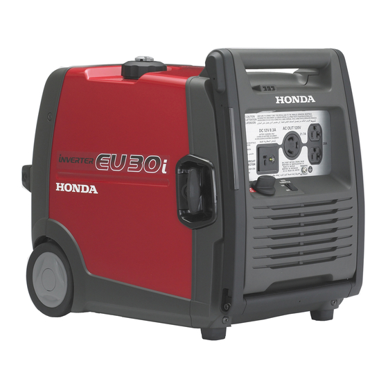
COMPONENT IDENTIFICATION FUEL TANK CAP VENT LEVER FUEL TANK CAP STARTER GRIP FOLDING HANDLE SPARK PLUG MAINTENANCE COVER AIR CLEANER COVER MUFFLER FRAME SERIAL NUMBER OIL MAINTENANCE COVER Record the frame serial number in the space below. You will need this serial number when ordering parts. -
Page 15: Control Panel
CONTROL PANEL G/G8, GW, F, RG types OVERLOAD INDICATOR AC RECEPTACLES OIL ALERT INDICATOR OUTPUT INDICATOR PARALLEL OPERATION SOCKETS AC CIRCUIT PROTECTOR (Except RG type) DC RECEPTACLE DC CIRCUIT PROTECTOR GROUND TERMINAL AC CIRCUIT PROTECTOR (Except RG type) ENGINE SWITCH ECO THROTTLE SWITCH IT type AC CIRCUIT PROTECTOR... - Page 16 U type OVERLOAD INDICATOR AC RECEPTACLES OIL ALERT INDICATOR OUTPUT INDICATOR PARALLEL OPERATION SOCKETS DC RECEPTACLE DC CIRCUIT PROTECTOR GROUND TERMINAL ENGINE SWITCH ECO THROTTLE SWITCH...
- Page 17 Eco Throttle ECO: Engine speed is kept at idle automatically when the electrical appliance is disconnected and it returns to the proper speed by the electrical load when electrical appliance is connected. This position is recommended to minimize the fuel consumption while in operation. Eco Throttle system does not operate sufficiently if the electrical appliance requires the momentary electric power.
-
Page 18: Pre-Operation Check
PRE-OPERATION CHECK Be sure to check the generator on a level surface with the engine stopped. Check the engine oil level. Using non detergent oil or 2-stroke engine oil could shorten the engine’s service life. Recommended oil Use 4-stroke motor oil that meets or exceeds the requirements for API service category SE or later (or equivalent). - Page 19 Open the oil maintenance cover. Remove the oil filler cap, and wipe the dipstick with a clean rag. Check the oil level by inserting the dipstick in the oil filler hole without screwing it in. If the oil level is below the end of the dipstick, refill with recommended oil up to the top of the oil filler neck.
- Page 20 Check the fuel level. If the fuel level is low, refuel the fuel tank until the level as specified. After refueling, tighten the fuel tank cap securely. Use automotive unleaded gasoline with a Research Octane Number of 91 or higher (a Pump Octane Number of 86 or higher). Never use stale or contaminated gasoline or an oil/gasoline mixture.
- Page 21 Gasoline spoils very quickly depending on factors such as light exposure, temperature and time. In worst cases, gasoline can be contaminated within 30 days. Using contaminated gasoline can seriously damage the engine (carburetor clogged, valve stuck). Such damage due to spoiled fuel is disallowed from coverage by the warranty.
- Page 22 Check the air cleaner. Check the air cleaner elements to be sure it is clean and in good condition. Loosen the air cleaner cover screw, and remove the air cleaner cover. Remove the main and outer elements from the air cleaner case, and check the elements.
- Page 23 Make sure that the rubber seal is set in the groove of the air cleaner case. Replace the rubber seal if it is damaged. Reinstall the main and outer elements. Put the outer element between the upper and lower ribs. AIR CLEANER CASE RUBBER SEAL RIBS...
-
Page 24: Starting The Engine
STARTING THE ENGINE Before starting the engine disconnect any load from the AC receptacle. Turn the fuel tank cap vent lever fully clockwise to the ON position. Turn the fuel tank cap vent lever to the OFF position when transporting the generator. FUEL TANK CAP VENT LEVER Turn the engine switch to the ON position. - Page 25 Pull the starter grip lightly until you feel resistance, then pull the starter grip briskly toward in the direction of the arrow as shown below. The starter grip can be drawn back very quickly before you release it. This may pull your hand forcefully toward the engine and cause an injury.
-
Page 26: Carburetor Modification For High Altitude Operation
Carburetor Modification for High Altitude Operation At high altitude, the standard carburetor air-fuel mixture will be too rich. Performance will decrease, and fuel consumption will increase. A very rich mixture will also foul the spark plug and cause hard starting. Operation at an altitude that differs from that at which this engine was certified, for extended periods of time, may increase emissions. -
Page 27: Generator Use
GENERATOR USE Be sure to ground the generator when the connected equipment is grounded. Do not connect to a building’s electrical system unless an isolation switch has been installed by a qualified electrician. Connections for standby power to a building’s electrical system must be made by a qualified electrician and must comply with all applicable laws and electrical codes. - Page 28 Do not exceed the current limit specified for any one receptacle. Do not connect the generator to a household circuit. This could cause the damage to the generator or to electrical appliances in the house. Do not modify or use the generator for other purposes than it is intended for.
- Page 29 AC applications Start the engine and make sure the Output indicator (green) comes Confirm that the appliance to be used is switched off, and plug in the appliance. OUTPUT INDICATOR (GREEN) OVERLOAD INDICATOR (RED) ECO THROTTLE SWITCH If you wish to use the Eco Throttle system, turn the Eco Throttle switch to the ECO position (see page Substantial overloading that continuously lights the Overload indicator (red) may damage the generator.
- Page 30 AC Circuit Protectors (G/G8, GW, F, IT types) The AC circuit protectors will automatically switch OFF (push button comes out) if there is a short circuit or a significant overload of the generator at receptacle. If an AC circuit protector switches OFF automatically, check that the appliance is working properly and does not exceed the rated load capacity of the circuit before resetting the AC circuit protector ON (pushing the push button in).
- Page 31 Output and Overload Indicators The Output indicator (green) will remain on during normal operating conditions. If the generator is overloaded (see page ), or if there is a short in the connected appliance, the Output indicator (green) will go off, the Overload indicator (red) will come on and current to the connected appliance will be shut off.
- Page 32 Please read the item ‘‘GENERATOR USE’’ before connecting any equipment to be used. Use only a Honda approved receptacle box for parallel operation (optional equipment except G8 type) when connecting two EU30i generators for parallel operation. RECEPTACLE BOX FOR PARALLEL OPERATION...
- Page 33 Never connect the different generator models and types. Never connect a cable other than the receptacle box for parallel operation. Connect and remove the receptacle box for parallel operation with the engine stopped. For single operation, the receptacle box for parallel operation must be removed.
- Page 34 Be sure to ground the generator when the connected equipment is grounded. GROUND TERMINAL Start the engines and make sure the Output indicators (green) come OUTPUT INDICATOR (GREEN) Confirm that the appliance to be used is switched off, and plug in the appliance.
- Page 35 DC application The DC receptacle may be used for charging 12 volt automotive-type batteries only. In DC operation, turn the Eco Throttle switch to the OFF position. Connect the charging cable to the DC receptacle of the generator and then to the battery terminals. CHARGING CABLE (Optional equipment) DC RECEPTACLE...
- Page 36 Batteries produce explosive gases: If ignited, and explosion can cause serious injury or blindness. Provide adequate ventilation when charging. CHEMICAL HAZARD: Battery electrolyte contains sulfuric acid. Contact with eyes or skin, even through clothing, may cause severe burns. Wear a faceshield and protective clothing. Keep flames and sparks away, and do not smoke in the area.
- Page 37 Oil Alert system The Oil Alert system is designed to prevent engine damage caused by an insufficient amount of oil in the crankcase. Before the oil level in the crankcase falls below a safe limit, the Oil Alert system will automatically shut down the engine (the engine switch will remain in the ON position).
-
Page 38: Stopping The Engine
STOPPING THE ENGINE To stop the engine in an emergency, turn the engine switch to the OFF position. IN NORMAL USE: Switch off the connected equipment and pull the inserted plug. Turn the engine switch to the OFF position. ENGINE SWITCH... - Page 39 Turn the fuel tank cap vent lever fully counterclockwise to the OFF position. FUEL TANK CAP VENT LEVER Be sure the fuel tank cap vent lever and the engine switch are in the OFF position when stopping, transporting and/or storing the generator.
-
Page 40: Maintenance
MAINTENANCE The purpose of the maintenance and adjustment schedule is to keep the generator in the best operating condition. Inspect or service as scheduled in the table below. Make sure the engine is off before you begin any maintenance or repairs. - Page 41 Tools A box wrench, spark plug wrench and wrench handle are supplied with the generator. Use the supplied tools to perform maintenance tasks. Using an incorrect tool may damage the generator. BOX WRENCH SPARK PLUG WRENCH WRENCH HANDLE...
- Page 42 CHANGING OIL Drain the oil while the engine is still warm to assure rapid and complete draining. Make sure to turn the engine switch and the fuel tank cap vent lever to the OFF position before draining. Place wood blocks under the generator to give a clearance of at least 90 mm (3.5 in) as shown.
- Page 43 Open the oil drain plug cover from the bottom of the generator. Place a suitable container under the oil drain plug. Remove the oil drain plug and sealing washer with the supplied box wrench and wrench handle, and drain the oil into the container thoroughly.
- Page 44 AIR CLEANER SERVICE A dirty air cleaner will restrict air flow to the carburetor. To prevent carburetor malfunction, service the air cleaner regularly. Service more frequently when operating the generator in extremely dusty areas. Do not use gasoline or low flash point solvents for cleaning. They are flammable and explosive under certain conditions.
- Page 45 Wash the elements in a solution of household detergent and warm water and rinse thoroughly, or wash in nonflammable or high flash point solvent. Allow the elements to dry thoroughly. If the elements are damaged, replace them. Soak the elements in clean engine oil and squeeze out the excess oil. 1.
- Page 46 SPARK PLUG SERVICE RECOMMENDED SPARK PLUG: BPR6ES (NGK) W20EPR-U (DENSO) To ensure proper engine operation, the spark plug must be properly gapped and free of deposits. If the engine is hot, allow it to cool before servicing the spark plug. Loosen the cover screw and remove the spark plug maintenance cover.
- Page 47 Visually inspect the spark plug. Discard it if the insulator is cracked, chipped, or fouled. Clean the spark plug with a wire brush if it is to be reused. Measure the plug gap with a feeler gauge. Correct as necessary by carefully bending the side electrode. The gap should be: 0.7 0.8 mm (0.028 0.031 in) 0.7 0.8 mm...
-
Page 48: Transporting/Storage
TRANSPORTING/STORAGE To prevent fuel spillage when transporting or during temporary storage, the generator should be secured upright in its normal operating position, with the engine switch OFF. The fuel tank cap vent lever is turned fully counterclockwise to the OFF position. - Page 49 Folding Handle The foldable handle is intended for ease of transportation and should be folded when the generator is stationary. Do not rest objects on FOLDING HANDLE the handle when in the transport position. To Extend The Handle Lift the handle upward with both hands. To Fold The Handle Lower the handle with both hands until it clicks into place.
- Page 50 Storage Before storing the generator for an extended period: Be sure the storage area is free of excessive humidity and dust. Drain the fuel. Gasoline is extremely flammable and is explosive under certain conditions. Perform this task in a well ventilated area with the engine stopped.
- Page 51 Change the engine oil (see page Remove the spark plug and pour about a tablespoon of clean engine oil into the cylinder. Crank the engine several revolutions to distribute the oil, then reinstall the spark plug. Slowly pull the starter grip until resistance is felt. At this point, the piston is coming up on its compression stroke and both the intake and exhaust valves are closed.
-
Page 52: Troubleshooting
TROUBLESHOOTING When the engine will not start: Is there fuel in Refill the fuel the tank? tank (see page Is the engine Turn the engine switch ON? switch on (see page Is the enough oil Add the in the engine? recommended oil (see page Is the spark plug... - Page 53 Appliance does not operate: Turn the AC G/G8, GW, F, IT types: circuit protector Is the AC circuit ON (see page protector ON? Is the output indicator on? Is the Overload Take the indicator on? generator to an authorized Honda dealer. Check the Take the electrical...
- Page 54 No electricity at the DC receptacle: Is the DC circuit Turn the DC protector ON? circuit protector ON (see page Take the generator to an authorized Honda dealer.
-
Page 55: Specifications
SPECIFICATIONS Dimensions and Weight Model EU30i Description code EAVJ Length 622 mm (24.5 in) Width 379 mm (14.9 in) Height 489 mm (19.3 in) Dry mass [weight] 35.2 kg (77.6 lbs) Engine Model GX160K1 Engine type 4-stroke, overhead valve, single cylinder Displacement 163 cm (9.9 cu-in) - Page 56 Noise EU30i Model G/G8, GW, F, IT RG, U Type 74 dB Sound pressure level (Lp ) According to 98/37/EC Microphone point CONTROL PANEL Center 1.60 m 1.0 m 92 dB Guaranteed sound power level (L Tested by 2000/14/EC ‘‘the figures quoted are emission levels and are not necessarily safe working levels.
-
Page 57: Wiring Diagram
WIRING DIAGRAM ACCP AC Circuit Protector BLACK ACNF AC Noise Filter YELLOW ACOR BLUE AC Output Receptacle Parallel operation socket GREEN Control Panel Block DCCP DC Circuit Protector WHITE DC Diode BROWN DCNF DC Noise Filter LIGHT GREEN DCOR DC Output Receptacle GRAY DC Winding LIGHT BLUE... - Page 58 G/G8, GW, F, IT, RG types...
- Page 59 U type...
- Page 60 RECEPTACLE Shape Type G/G8, GW, RG...
-
Page 61: Major Honda Distributor Address
MAJOR Honda DISTRIBUTOR ADDRESSES For further information, please contact Honda Customer Information Centre at the following address or telephone number: AUSTRIA CROATIA FINLAND Honda Motor Europe (North) Hongoldonia d.o.o. OY Brandt AB. Hondastraße 1 Jelkovecka Cesta 5 Tuupakantie 7B 2351 Wiener Neudorf... - Page 62 HUNGARY NETHERLANDS ROMANIA Motor Pedo Co., Ltd. Honda Motor Europe (North) Hit Power Motor Srl Kamaraerdei ut 3. Afd. Power Equipment- Calea Giulesti N° 6-8 Sector 6 2040 Budaors Capronilaan 1 060274 Bucuresti Tel. : 36 23 444 971 1119 NN Schiphol-Rijk Tel.
- Page 63 SPAIN & TURKEY AUSTRALIA Las Palmas province Anadolu Motor Uretim ve Honda Australia Motorcycle (Canary Islands) Pazarlama AS and Power Equipment Pty. Ltd Greens Power Products, S.L. Esentepe mah. Anadolu 1954-1956 Hume Highway Poligono Industrial Congost - Cad. No: 5 Campbellfield Victoria 3061 Av Ramon Ciurans n°2 Kartal 34870 Istanbul...
Need help?
Do you have a question about the EU30i and is the answer not in the manual?
Questions and answers