Table of Contents
Advertisement
Quick Links
Effective : April, 2002
SERVICE MANUAL
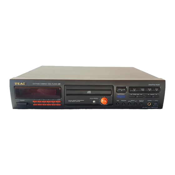
C C D D - - P P 1 1 4 4 5 5 0 0
COMPACT DISC PLAYER
CONTENTS
1 SPECIFICATIONS
2 EXPLODED VIEWS AND PARTS LIST
3 PC BOARDS AND PARTS LIST
4 INCLUDED ACCESSORIES
NOTES
PC boards shown are viewed from parts side.
The parts with no reference number or no parts number in the
exploded views are not supplied.
As regards the resistors and capacitors, refer to the circuit diagrams
contained in this manual.
Parts marked with this sign are safety critical components. They
£
must be replaced with identical components - refer to the appropriate
parts list and ensure exact replacement.
Parts of [ ] mark can be used only with the version designated.
2
3
8
13
S-0060A
Advertisement
Table of Contents

Subscribe to Our Youtube Channel
Related Manuals for Teac CD-P1450


Summary of Contents for Teac CD-P1450
- Page 1 SERVICE MANUAL C C D D - - P P 1 1 4 4 5 5 0 0 COMPACT DISC PLAYER CONTENTS 1 SPECIFICATIONS 2 EXPLODED VIEWS AND PARTS LIST 3 PC BOARDS AND PARTS LIST 4 INCLUDED ACCESSORIES NOTES PC boards shown are viewed from parts side.
-
Page 2: Specifications
1 SPECIFICATIONS CD PLAYER GENERAL Pickup: Power Requirements: 3-beam, semiconductor laser 120 V AC, 60Hz (U.S.A./Canada Model) D/A Converter: 230 V AC, 50Hz (Europe/U.K. Model) 1 bit DAC 240 V AC, 50Hz (New Zealand Model) Digital filter: Power Consumption: 8-times oversampling 12 Watts (AC) Frequency Response: Dimensions (W x H x D):... -
Page 3: Exploded Views And Parts List
2 EXPLODED VIEWS AND PARTS LIST EXPLODED VIEW-1 51SC2 51SC2 51SC2 51SC2 45-1 5142 5108 5116 5104 51SB3 5140 5118 45-4... - Page 4 EXPLODED VIEW-1 £ £ £ £ £...
- Page 5 EXPLODED VIEW-1...
- Page 6 EXPLODED VIEW-2...
- Page 7 EXPLODED VIEW-2 (CD93F8NDT)
-
Page 8: Pc Boards And Parts List
3 PC BOARDS AND PARTS LIST MAIN PCB... - Page 9 DISPLAY PCB KEY SW PCB HP PCB PITCH CON PCB...
- Page 10 POWER PCB...
- Page 11 MAIN PCB ASSY DISPLAY PCB ASSY £ £ £ £ KEY SW PCB ASSY £ £ PITCH CON PCB ASSY £ £ £ £ H.P. PCB ASSY £...
- Page 12 POWER PCB ASSY £ £ £ £ £ £ £ £ £ £...
-
Page 13: Included Accessories
4 INCLUDED ACCESSORIES INCLUDED ACCESSORIES... - Page 14 CD-P1450 SCHEMATIC DIAGRAM Main Circuit S02 OP/CL CN101 R403 100K CL SW C401 IC401A OP SW CN104 10/16 C403 R401 0 NJM4556 PH11 220/16 R133 R409 33 R134 C412 P401 7.5K R405 50K-A TRAY MOTOR TO HEADPHONE 100/10 X301 5.00MHz...
- Page 15 CD-P1450 SCHEMATIC DIAGRAM Audio Circuit C509 220P JK501A RCA-L C503 R527 R519 R509 R505 R501 C515 180P 2.2K 1.8K 6.8K Q501 IC501B 2.2/50 R529 2SD1936 NJM2068D C507 100K IC502B R525 220P NJM4558D C519 C505 R515 R513 R503 1000P R521 C517 5.6K...
- Page 16 CD-P1450 SCHEMATIC DIAGRAM Control Circuit NOTES: 1. Resistor values are in ohms (k=kilo-ohms, M=megohms). 2. Capacitor values are in microfarads (p=picofarads). 3. £Parts marked with this sign are safety critical components. They must always be replaced with identical components-refer to the appropriate parts list and ensure exact replacement.
-
Page 17: Schematic Diagram
CD-P1450 SCHEMATIC DIAGRAM Power Circuit SW201 T201 SW-POWER 4L50006430 J202 LIVE POWERCORD EC202 W501 CN201 EC-TERMINAL CONNECTOR 5P ASSY TO PCB MAIN C201 0.01uF CN202 J201 CN105 120V NEUTRAL EC201 230V EC-TERMINAL SW201 T201 SW-POWER F201 LIVE 230V POWERCORD T630mA/250V...
Need help?
Do you have a question about the CD-P1450 and is the answer not in the manual?
Questions and answers