Benchmark DAC2 Series Instruction Manual
Dac2 series reference stereo preamplifier
Hide thumbs
Also See for DAC2 Series:
- Instruction manual (50 pages) ,
- Instruction manual (68 pages) ,
- Instruction manual (65 pages)
Table of Contents
Advertisement
Quick Links
Download this manual
See also:
Instruction Manual
Advertisement
Table of Contents

Related Manuals for Benchmark DAC2 Series


Summary of Contents for Benchmark DAC2 Series
- Page 1 DAC2 Series Benchmark Instruction Manual Reference Stereo Preamplifier PCM and DSD D/A Converter Asynchronous USB...
-
Page 3: Safety Information
POWER CORD. THE PRODUCT IS EQUIPPED WITH A STANDARD IEC POWER ENTRY MODULE. USE AN IEC POWER CORD THAT IS EQUIPPED WITH THE APPROPRIATE CONNECTOR FOR YOUR LOCATION. CORDS ARE AVAILABLE FROM YOUR DEALER. DAC2 Series Instruction Manual Rev C Page 3... -
Page 4: Table Of Contents
AC Power-Entry and Fuse Module Benchmark 1 Year Warranty Fuses Benchmark Extended Warranty Voltage Selection Power Cord Internal Settings Removing Top Cover Low-Impedance Passive Pads Jumpers Digital Pass Through System1™ Universal Rack Adapter Blank Rack Panel DAC2 Series Instruction Manual Rev C Page 4... -
Page 5: Features
Features The DAC2 series is a reference-grade digital to analog converter, stereo system pre-amplifier, and headphone amplifier with infrared remote control. It supports D/A conversion of PCM sample rates up to 192 kHz, as well as direct DSD conversion. HGC™ (Hybrid Gain Control) – combines motor-driven active analog potentiometer, 32-bit... -
Page 6: Overview
Overview The DAC2 builds upon Benchmark’s highly The unit runs cool while providing substantial successful DAC1 product family. Every DAC1 power to the headphone and output drivers. subsystem has been redesigned and A power switch is included. upgraded to achieve higher performance. -
Page 7: New Features
(Note: DAC1 users will find this New Hybrid Gain Control function to be similar to the DAC1’s calibrated mode.) HGC™ is Benchmark’s unique Hybrid Gain Control that combines active analog, 32-bit Digital Pass-Through digital, and passive analog attenuation systems. HGC™ puts an end to the debate... -
Page 8: Expanded I/O
The pristine audio performance of the award- Bi-directional 12V Trigger (DAC2 winning DAC1 made it the ‘Benchmark’ of stand-alone D/A converters. The DAC1 USB HGC and DAC2 L model only) and DAC1 PRE , and DAC1 HDR added... - Page 9 The near 0-Ohm output impedance provides outstanding damping of headphone drivers. This damping reduces distortion, and maintains control of the frequency response. DAC2 Series Instruction Manual Rev C Page 9...
-
Page 10: Quick Start Guide
Remote Control Analog Cycle through analog input A1 The remote-control has the following and A2 (DAC2 HGC and DAC2 L functions (and their respective icons): model only) DAC2 Series Instruction Manual Rev C Page 10... -
Page 11: Direct Interfacing To Power Amplifiers
‘Mute’ mode, the volume will ramp up to the inserted. This feature allows the listener to ‘Normal’ volume setting. switch from loudspeaker to headphone playback seamlessly. This mute feature can be disabled with internal jumpers. DAC2 Series Instruction Manual Rev C Page 11... -
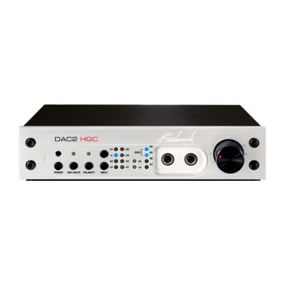
Page 12: Front Panel
Front Panel DAC2 Series Instruction Manual Rev C Page 12... -
Page 13: Input Status Display
D3 – The blue blinking LED indicates no 192 kHz. If both the 2X and the 4X LEDs are signal is transmitted to coaxial RCA digital input 3 or data transmitted is incompatible. A DAC2 Series Instruction Manual Rev C Page 13... -
Page 14: Button Functions
USB mode. Doing so might freeze your computer. Pressing and holding the USB button on the remote for 2 seconds will also change the USB mode. DAC2 Series Instruction Manual Rev C Page 14... -
Page 15: Input Status Display
TIP: For optimal performance, the DSD = 2X and 4X LEDs headphone gain jumpers should be set so that comfortable listening levels occur when the ‘Volume Control’ is set above the ‘11 o’clock’ position. DAC2 Series Instruction Manual Rev C Page 15... -
Page 16: Hgc™ Volume Control
Experience the new details in your favorite recordings. Hybrid Gain Control™ The front-panel volume control is a servo- "HGC" is Benchmark's unique Hybrid Gain driven gain circuit control built around a Control™ system. The DAC2 combines custom-made Alps potentiometer. The... -
Page 17: Rear Panel
There are seven stereo inputs on the DAC2: The Benchmark UltraLock2™ system 2 x Analog (DAC2 HGC and DAC2 L model removes interface jitter from all digital inputs DAC2 Series Instruction Manual Rev C Page 17... -
Page 18: Dac2 Series Instruction Manual
RF shielding. X for 192 kHz and DSD playback. TIP: Shielded 75-Ohm coaxial cable is On USB 1.1, the Benchmark USB interface is required for stable performance. Do not truly a plug-and-play solution. The DAC2 can use 50-Ohm cables or twisted pair begin streaming high resolution 24-bit/96 kHz cables, or any non-coaxial cables. - Page 19 IEC 609588-3 specifies 75-Ohm 0.5 Vpp consumer-format digital audio signals (commonly known as S/PDIF). The coaxial inputs on the DAC2 are designed to accept either type of signal. DAC2 Series Instruction Manual Rev C Page 19...
-
Page 20: Outputs
TIP: The RCA outputs are capable of Internal Setting section of this manual. driving cables as long as 1360 feet (see DAC2 Series Instruction Manual Rev C Page 20... -
Page 21: Ac Power-Entry And Fuse Module
INCLUDES TWO FUSES. ALWAYS REPLACE BOTH FUSES AT THE SAME TIME. Voltage Selection THE DAC2 IS EQUIPPED WITH A UNIVERSAL POWER SUPPLY. THERE IS NO VOLTAGE SELECTION SWITCH. AC VOLTAGE RANGE IS 88-264 VAC, 50-60 DAC2 Series Instruction Manual Rev C Page 21... -
Page 22: Internal Settings
Impedance Cable (ft) at 20 kHz 1360 TIP: To set the XLR outputs to typical professional studio levels, set the pads to 0 dB. For most home installations, set the pads to 10 dB or 20 dB. DAC2 Series Instruction Manual Rev C Page 22... -
Page 23: Jumpers
-20 dB – (Jumper plug between pins 5 and 6 of each header) Figure 2 *** - Factory Default Figure 3 - Disable Heaphone Switch Figure 1 - 10 dB (Factory Default) DAC2 Series Instruction Manual Rev C Page 23... - Page 24 5 - 0 dB for more gain or move the jumpers according to example in Figure 6 - 20 dB for less gain. Figure 6 - 20 dB Figure 4 - 10 dB (Factory default) DAC2 Series Instruction Manual Rev C Page 24...
-
Page 25: Digital Pass Through
By default, D4 functions as a digital input so the jumpers are set according to Figure 8. Figure 8 - (Factory default) Figure 7 – Digital Pass Through enabled DAC2 Series Instruction Manual Rev C Page 25... -
Page 26: System1™ Universal Rack Adapter
The Universal Rack Mount Adapter is a products in a single rack space. A Blank tray that mounts up to two ½ RU Benchmark Rack Panel can be added when only one unit products in a single race space. The tray is installed in the rack mount adapter. -
Page 27: Benchmark Technologies
Technologies Multi-Mode Asynchronous AdvancedUSB Audio™ Hybrid Gain Control™ Benchmark's USB system supports USB Audio "HGC" is Benchmark's unique Hybrid Gain 2.0, DSD, and USB Audio 1.1. It is frequency Control™ system. The DAC2 combines agile, and will follow sample rate changes... -
Page 28: Jitter-Immune Ultralock2
PCM system until they reach an interpolation process. But, for a Benchmark re-invents the 12 volt trigger. variety of reasons, virtually all audio D/A The trigger connection on the DAC2 can be converters use an interpolation process. The... -
Page 29: Hpa2™ Headphone Amplifier
‘interface jitter’ and it is present even in the In general, distortion increases as headphone most carefully designed audio systems. impedance decreases. This distortion can be DAC2 Series Instruction Manual Rev C Page 29... - Page 30 No jitter- harmonic distortion, and more audible than induced artifacts can be detected using an THD measurements would suggest. Audio Precision System 2 Cascade test set. DAC2 Series Instruction Manual Rev C Page 30...
- Page 31 D/A converters are the only true ensurance These crosstalk problems may not become against the ill effects of jitter. UltraLock2™ obvious until jitter is present. converters are jitter-immune under all operating conditions (they will never add DAC2 Series Instruction Manual Rev C Page 31...
- Page 32 A/D with a jitter problem was used to create a jitter. digital audio signal, then there is nothing that can be done to remove the damage. Jitter- induced sidebands are extremely complex and DAC2 Series Instruction Manual Rev C Page 32...
-
Page 33: Multi-Mode Asynchronous Usb Audio System
Benchmark USB device in USB 1.1, playing tracks up to 96 kHz 24-bit. Any audio played from the computer will then be routed to the Benchmark USB device immediately. There is no software to install or configure. -
Page 34: Usb Driver Installation - Windows Xp, Vista
Note: The DAC2 driver is available for download at: http://www.benchmarkmedia.com/dac/dac2- hgc/driver Before you install the driver, make sure the USB is unplugged before installation of the driver. 1. In the DAC2 Driver folder, double click “setup.exe.” DAC2 Series Instruction Manual Rev C Page 34... - Page 35 2. A welcome screen will pop-up. Click “Next.” DAC2 Series Instruction Manual Rev C Page 35...
- Page 36 4. You will be prompted to select a location to install the driver in. It will default to your Program Files folder. If you wish to install it another location, you can change the location. We suggest keeping it in the default destination folder. DAC2 Series Instruction Manual Rev C Page 36...
- Page 37 Press “Install” DAC2 Series Instruction Manual Rev C Page 37...
- Page 38 When the installation begins you will see the following screen. Please be patient while the driver installs. Installation time is between 1-5 minutes. 6. Once the installation finishes a message at the top will say “Installation Complete.” Press “Next” to continue. DAC2 Series Instruction Manual Rev C Page 38...
- Page 39 7. Click “Finish.” The Setup will close automatically and this completes the installation process. You can now enjoy music up to 192 kHz and DSD. DAC2 Series Instruction Manual Rev C Page 39...
-
Page 40: Performance Graphs
The rise at 0 Hz is normal in an FFT analysis and is not an indication of noise. This 32k point FFT analysis uses a Blackman-Harris window with 16x power averaging, and spans a frequency range of DC to 32 kHz. DAC2 Series Instruction Manual Rev C Page 40... - Page 41 60 Hz and 180 Hz (frequencies where we would expect to see interference from the 60 Hz AC input. There is absolutely no sign of any AC hum. DAC2 Series Instruction Manual Rev C Page 41...
- Page 42 The rise at 0 Hz is normal in an FFT analysis and is not an indication of noise. This 32k point FFT analysis uses a Blackman-Harris window with 16x power averaging, and spans a frequency range of DC to 32 kHz. DAC2 Series Instruction Manual Rev C Page 42...
- Page 43 The rise at 0 Hz is normal in an FFT analysis and is not an indication of noise. This 32k point FFT analysis uses a Blackman-Harris window with 16x power averaging, and spans a frequency range of DC to 32 kHz. DAC2 Series Instruction Manual Rev C Page 43...
- Page 44 Graph Plot 5 - FREQUENCY RESPONSE This plot demonstrates the ruler-flat frequency response of the DAC2. Note that the frequency response measures - 0.01 dB at 10 Hz and -0.02 dB at 40 kHz. DAC2 Series Instruction Manual Rev C Page 44...
- Page 45 5.1 surround system. Four DAC2 converters can be combined to form a 7.1 system. The phase accuracy between any two channels will match the phase accuracy shown above. DAC2 Series Instruction Manual Rev C Page 45...
- Page 46 AP 2700 test set. The THD+N measurements on the unbalanced outputs confirm the effectiveness of the differential amplifiers. Similar results are obtained by measuring either side of the balanced outputs relative to ground. DAC2 Series Instruction Manual Rev C Page 46...
- Page 47 SABRE converters. These differential amplifiers give the unbalanced outputs the ability to approach the performance of the balanced outputs. Please note that the differential amplifiers also eliminate common-mode distortion on the balanced outputs. DAC2 Series Instruction Manual Rev C Page 47...
- Page 48 This plot shows the THD+N performance of the headphone outputs under load. Note that the THD+N performance of the headphone outputs approaches that of the balanced outputs. The DAC2 includes Benchmark's HPA2(TM) headphone amplifier. The HPA2(TM) has a near 0-Ohm output impedance which provides outstanding control and damping of the headphone drivers. The HPA2(TM) has the voltage and current drive necessary to drive a wide variety of headphones.
- Page 49 The analog output stages on the DAC2 have high slew rates and are capable of maintaining low THD levels at high frequencies even when driven to 0 dBFS. Note that there is almost no rise in THD+N with frequency, even when operating at maximum output levels. DAC2 Series Instruction Manual Rev C Page 49...
- Page 50 Note that odd harmonics are lower than the more "musical" even harmonics. Both sets of harmonics are very low in amplitude (-112 dB to -120 dB), and should be entirely inaudible. DAC2 Series Instruction Manual Rev C Page 50...
- Page 51 The unbalanced outputs, and the headphone outputs, closely match the performance of the balanced outputs. Like Graph Plot 11 - EVEN AND ODD THD vs. FREQUENCY, this plot shows THD (not THD+N). DAC2 Series Instruction Manual Rev C Page 51...
- Page 52 Anlr.THD+N Ratio Left Solid Anlr.THD+N Ratio Left DAC2 - THD+N vs Sample Rate.at27 Graph Plot 13 - THD+N versus Sample Rate The THD+N performance of the DAC2 is identical at all Sample Rates. DAC2 Series Instruction Manual Rev C Page 52...
- Page 53 Over the entire range of the AES jitter tolerance test, the THD+N performance of the DAC2 is unchanged. The DAC2 easily passes the AES jitter tolerance test without any THD+N performance degradation. DAC2 Series Instruction Manual Rev C Page 53...
- Page 54 FIGURE 8. The DAC2 shows no change in performance when the AES jitter tolerance test is applied to the digital inputs. No jitter-induced sidebands are visible to a measurement limit that exceeds -140 dBFS. DAC2 Series Instruction Manual Rev C Page 54...
- Page 55 This plot demonstrates that the DAC2 has very low IMD distortion. The 1 kHz difference frequency measures -122 dB, and the 10 kHz and 13 kHz products measure about -128 dB. IMD distortion should be well below audible levels. DAC2 Series Instruction Manual Rev C Page 55...
-
Page 56: Specifications
Inter-channel Differential Phase (Stereo Pair – any +/- 0.25 degrees at 20 kHz sample rate) Inter-channel Differential Phase (Between DAC2 HGC +/- 0.25 degrees at 20 kHz Units Fs<110 kHz) Any sample rate. DAC2 Series Instruction Manual Rev C Page 56... -
Page 57: Group Delay (Latency)
1.36 ms at 44.1 kHz sample rate) 1.27 ms at 48 kHz 0.90 ms at 88.2 kHz 0.82 ms at 96 kHz 0.51 ms at 176.4 kHz 0.47 ms at 192 kHz DAC2 Series Instruction Manual Rev C Page 57... -
Page 58: Analog Audio Inputs
Off to +10.5 dB (RCA in to Headphone) Factory-Set Analog-Input Gain In Home Theater Bypass +0 dB (RCA in to RCA out) Mode 6 dB (RCA in to XLR out) (w/10dB Pad) DAC2 Series Instruction Manual Rev C Page 58... -
Page 59: Digital Audio Inputs
>1.5 UI sine at 40 kHz >1.5 UI sine at 80 kHz >1.5 UI sine at 90 kHz >0.25 UI sine above 160 kHz Jitter Attenuation Method Benchmark UltraLock2™ - all inputs DAC2 Series Instruction Manual Rev C Page 59... -
Page 60: Balanced Analog Outputs
Factory Set Home Theater Bypass Output Level (at 0 +7.5 dBu (1.77 Vrms) dBFS) Output Level Range (at 0 dBFS) Off to +7.5 dBu Output Level Variation with Sample Rate (44.1 kHz vs. < +/- 0.006 dB 96 kHz) DAC2 Series Instruction Manual Rev C Page 60... -
Page 61: Hpa2 Tm Headphone Outputs
Indicators - Type and Location 16 LED’s on Front Panel Selection/Status Indication 1 – Dim/Mute 7 – Input 1 – Home Theater Bypass/High Throughput Mode 1 – Polarity 2 – Word length 4 – Sample Rate DAC2 Series Instruction Manual Rev C Page 61... -
Page 62: Ac Power Requirements
9.33” (237 mm) cord Width 9.5” (249 mm) Height 1.725” (44.5 mm) Weight DAC2 only 3 lb. DAC2 with remote control, power cord, extra fuses, and 4 lb. manual Shipping weight 7 lb. DAC2 Series Instruction Manual Rev C Page 62... -
Page 63: Regulatory Compliance
(European Union) directive 2002/95/EC, or, RoHS (Restrictions of Hazardous Substances). As of July 01, 2006, All Benchmark Media Systems, Inc. products placed on the European Union market are compliant (containing quantity limit weight less than or equal to 0.1% (1000 ppm) of any homogeneous Lead (Pb), Mercury (Hg), Hexavalent Chromium (Cr VI), and flame retardant Polybrominated Biphenyls (PBB) or Polybrominated Diphenyl Ethers (PBDE)). -
Page 64: Ce Certificates Of Conformity
CE Certificates of Conformity DAC2 Series Instruction Manual Rev C Page 64... -
Page 65: Warranty Information
In the event of failure of a product under this warranty, Benchmark Media Systems, Inc. will repair, at no charge, the product returned to its factory. Benchmark Media Systems, Inc. may, at its option, replace the product in lieu of repair. -
Page 66: Benchmark Extended Warranty
Benchmark Extended Warranty The Benchmark Extended 5* Year Warranty Benchmark Media Systems, Inc. optionally extends the standard one (1) year warranty to a period of five (5)* years from the date of delivery. *For the extended warranty to become effective, the original purchaser must register the product at the time of purchase either by way of the enclosed registration card or through the product registration section of the Benchmark Media Systems, Inc. - Page 67 Copyright © 2007, 2008, 2009, 2012 Benchmark Media Systems, Inc. All rights reserved. Benchmark Media Systems, Inc. Benchmark Media Systems, Inc. 203 East Hampton Place, STE 2 Syracuse, NY 13206-1633 PHONE: +1-315-437-6300 FAX: +1-315-437-8119 www.benchmarkmedia.com DAC2 Series Instruction Manual Rev C Page 67...
Need help?
Do you have a question about the DAC2 Series and is the answer not in the manual?
Questions and answers