
Related Manuals for Benchmark LA4


Summary of Contents for Benchmark LA4
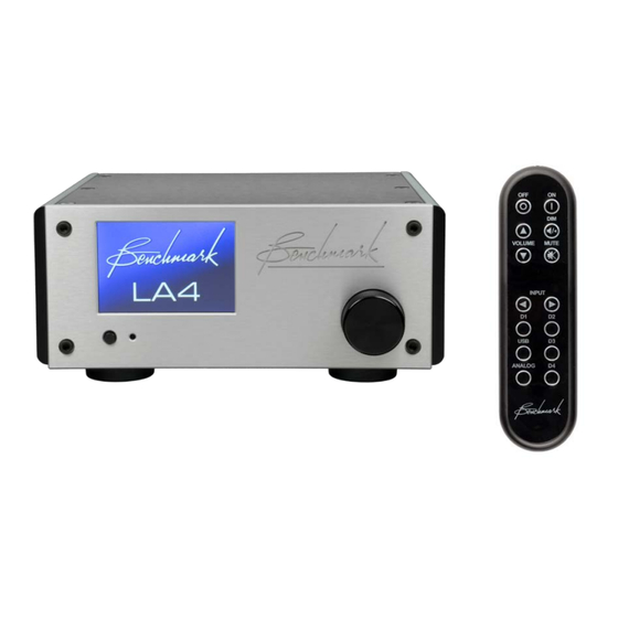
- Page 1 Benchmark LA4 Instruction Manual Reference Stereo Line Amplifier with Relay Gain and Input Control...
-
Page 2: Safety Information
EQUIPPED WITH A STANDARD IEC POWER ENTRY MODULE. USE AN IEC POWER CORD THAT IS EQUIPPED WITH THE APPROPRIATE CONNECTOR FOR YOUR LOCATION. CORDS ARE AVAILABLE FROM YOUR DEALER. Instruction Manual for LA4 with 1.0.X Firmware – REV A Page 2... -
Page 3: Table Of Contents
REMOTE Settings ABOUT Screens Warranty Information SPLASH SCREEN Benchmark 1-Year Warranty RESET Screens Benchmark Extended Warranty Options 48 Notes on Warranty Repairs LA4 System Overview The Ultimate Line Amplifier Instruction Manual for LA4 with 1.0.X Firmware – REV A Page 3... -
Page 4: Front Panel
Front Panel Rear Panel Instruction Manual for LA4 with 1.0.X Firmware – REV A Page 4... -
Page 5: Features
High-Efficiency Low-Noise Power Supplies – 100-240 VAC, 50-60 Hz Meets FCC Class B and CE emissions requirements Tested for immunity to radiated and conducted RF interference Instruction Manual for LA4 with 1.0.X Firmware – REV A Page 5... -
Page 6: Quick Start Guide
Quick Start Guide Main Screen Instruction Manual for LA4 with 1.0.X Firmware – REV A Page 6... -
Page 7: Balance Controls
Balance Controls Instruction Manual for LA4 with 1.0.X Firmware – REV A Page 7... -
Page 8: Screen Navigation
Screen Navigation Instruction Manual for LA4 with 1.0.X Firmware – REV A Page 8... -
Page 9: Display Settings
Display Settings Instruction Manual for LA4 with 1.0.X Firmware – REV A Page 9... -
Page 10: Remote Control
DAC if connected. Selects input D4 on Benchmark DAC if connected. Selects USB input on Benchmark DAC if connected. Analog Selects analog input(s) on Benchmark DAC if connected. Instruction Manual for LA4 with 1.0.X Firmware – REV A Page 10... -
Page 11: Front Panel Controls
The 12V TRIGGER I/O can be used as a trigger output to control the power state of additional components. The chart at the right summarizes the functions of the power button and volume knob. Instruction Manual for LA4 with 1.0.X Firmware – REV A Page 11... -
Page 12: Connecting Other Audio Components Use Balanced Interfaces When Possible
10 dB boost or cut without sacrificing performance. Selecting Components for Your System Select devices with balanced XLR inputs and outputs. Balanced interfaces are vastly superior to unbalanced RCA interfaces. Instruction Manual for LA4 with 1.0.X Firmware – REV A Page 12... -
Page 13: Connecting Benchmark Components
MUTE and DIM on on or off in a sequenced fashion. all devices. 3. Use XLR cables to connect the DAC to INPUT 1 on the LA4. This input Instruction Manual for LA4 with 1.0.X Firmware – REV A Page 13... -
Page 14: Basic Features
Balance Adjust Press the BAL button on the HOME screen to change the L/R balance of the line outputs. Instruction Manual for LA4 with 1.0.X Firmware – REV A Page 14... -
Page 15: Advanced Features (Settings Screens)
Remote (IR Enable, DAC Mode) About (System Information) • Display Settings • Input Setup • Lock/Unlock Advanced Settings • Settings 3 Reset Advanced Settings • Full Factory Reset • Instruction Manual for LA4 with 1.0.X Firmware – REV A Page 15... -
Page 16: Display Settings
DISPLAY Settings 2 DISPLAY Settings Screen Dim Timer • 'WAKE ON VOLUME' Function Display Settings 1 • Maximum Screen Brightness • Screen Brightness when Dimmed • Instruction Manual for LA4 with 1.0.X Firmware – REV A Page 16... - Page 17 DISPLAY Settings 3 Display Sleep Timer (screen off) • Menu Timer (return to home page) • Instruction Manual for LA4 with 1.0.X Firmware – REV A Page 17...
-
Page 18: Input Setup
• Disable/Enable Inputs Boost Adjust (input volume offset) • • • Volume Setup for Each Input SETTINGS LOCK RENAME INPUT Lock/Unlock Advanced Settings • Input Name Edit • Instruction Manual for LA4 with 1.0.X Firmware – REV A Page 18... -
Page 19: Power Settings
POWER Settings Auto-On - Enable/Disable • 12V Trigger Mode • Instruction Manual for LA4 with 1.0.X Firmware – REV A Page 19... -
Page 20: Remote Settings
REMOTE Settings • Enable IR Remote Control Integrate with Benchmark DAC • Instruction Manual for LA4 with 1.0.X Firmware – REV A Page 20... -
Page 21: About Screens
May be manually enabled from ABOUT • Software Version (touch screen) screen (this does not mute the audio, • touch the screen to exit). ABOUT BENCHMARK • Benchmark Contact Information Instruction Manual for LA4 with 1.0.X Firmware – REV A Page 21... -
Page 22: Reset Screens
RESET Screens FACTORY RESET Reset all Advanced Settings Including RESET SETTINGS • Input Names Reset all Advanced Settings Except • Input Names Instruction Manual for LA4 with 1.0.X Firmware – REV A Page 22... -
Page 23: La4 System Overview
100% Analog Signal Path deep, full and well damped. For this reason, all Benchmark products feature low-frequency The LA4 is 100% analog. It is designed to be extension to 0.1 Hz. driven from external D/A converters and external analog sources. The LA4 is designed... -
Page 24: Rotary Encoder
The LA4 will pull the amplifier. The magnetic fields produced by trigger I/O to 12 volts DC while the LA4 is the power amplifier may interfere with the on. If the LA4 is off and an external device LA4. -
Page 25: Auto-Ranging Power Supply
AC line voltage. There are no settings or fuses to change for international operation. Select a grounded IEC power cord that matches the AC outlets in your country. Instruction Manual for LA4 with 1.0.X Firmware – REV A Page 25... -
Page 26: Audio Line Inputs
15.8 dB so that assumed to be 15.8 dB hotter than they will match the level of the professional- unbalanced. grade balanced inputs. If the 15.8 dB default Instruction Manual for LA4 with 1.0.X Firmware – REV A Page 26... -
Page 27: Advanced Feature Details
The 12V TRIGGER I/O can be used to turn Typical trigger applications: other audio components on when the LA4 turns on. The LA4 can also turn on and off in LA4 → Amplifier response to other connected components. The •... -
Page 28: Software Version Identification
Tip: The trigger ports can be connected with If the LA4 is used to turn the system on, any 2-conductor or 3-conductor 1/8" (3.5 mm) connected AHB2 amplifiers will become slave cables. The 3rd conductor is not used. -
Page 29: Performance Graphs
Graph 1 - Stepped Gain Control - THD vs. Gain (-15 dB to +15 dB) The relay-controlled stepped gain controls are a key feature of the LA4. The stepped gain control is designed to provide volume control over a wide operating range without adding any significant noise or distortion. - Page 30 This shows that the active balanced output buffers do not add any significant noise to the stepped gain control. The active output buffers are important because they provide low impedance drive to downstream devices (such as power amplifiers). Instruction Manual for LA4 with 1.0.X Firmware – REV A Page 30...
- Page 31 0-dBu test tone. The small +/- 0.003 dB random variations shown are due to the measurement limitations of the AP2722. Balanced inputs to balanced line outputs, volume control set at 0 dB. • Instruction Manual for LA4 with 1.0.X Firmware – REV A Page 31...
- Page 32 Notes: The vertical scale is the phase difference between the left and right channels. • Balanced inputs to balanced outputs, volume control set at 0 dB. • Instruction Manual for LA4 with 1.0.X Firmware – REV A Page 32...
- Page 33 Graph 5 - FFT Idle Channel Noise - Balanced In to Balanced Out The LA4 is an exceptionally quiet line amplifier. This allows it to be inserted between a Benchmark DAC3 and an AHB2 power amplifier without degrading the noise performance of the system.
- Page 34 The scale on the right (dBr B) is dB relative to +22 dBu. This is the input level required to • drive an external AHB2 power amplifier to full output power. Balanced inputs to balanced line outputs, volume control set at 0 dB. • Instruction Manual for LA4 with 1.0.X Firmware – REV A Page 34...
- Page 35 Balanced inputs to balanced line outputs, volume control set at 0 dB. • • The 1 kHz fundamental has been removed using a notch filter. This filter increases the resolution of the AP2722 test system. Instruction Manual for LA4 with 1.0.X Firmware – REV A Page 35...
- Page 36 Unbalanced inputs to unbalanced line outputs, volume control set at 0 dB. • The 1 kHz fundamental has been removed using a notch filter. This filter increases the • resolution of the AP2722 test system. Instruction Manual for LA4 with 1.0.X Firmware – REV A Page 36...
- Page 37 Balanced inputs to balanced line outputs, volume control set at 0 dB. • • The 10 kHz fundamental has been removed using a notch filter. This filter increases the resolution of the AP2722 test system. Instruction Manual for LA4 with 1.0.X Firmware – REV A Page 37...
-
Page 38: Specifications
Volume Control Range (with 0 dBFS digital input) Mute, -112 dB to +15 dB in 0.5 dB steps Balance Control Range +/- 6 dB in 0.5 dB steps Instruction Manual for LA4 with 1.0.X Firmware – REV A Page 38... -
Page 39: Balanced Analog Inputs
90 – 260 VAC, 47 - 63 Hz Power < 0.5 Watts Standby 12 Watts Typical Program 17 Watts Maximum Fuses (2 required) 5x20 mm, 0.5 A 250 V Slo-Blo ® Type Instruction Manual for LA4 with 1.0.X Firmware – REV A Page 39... -
Page 40: Dimensions
Model Numbers The LA4 model number is 450-17100-XXX XXX is a code for color options The boxed product with manual is 500-17100-XXX XXX is a code for color options Instruction Manual for LA4 with 1.0.X Firmware – REV A Page 40... -
Page 41: Ac Power-Entry And Fuse Module
The LA4 is equipped with a standard IEC power entry module. Use an IEC power cord that is equipped with the appropriate connector for your location. Cords are available from your dealer. Instruction Manual for LA4 with 1.0.X Firmware – REV A Page 41... -
Page 42: Regulatory Compliance
2. This device must accept any interference received including interference that may cause undesired operation. NOTICE: Changes or modifications not expressly approved by the party responsible for compliance could void the user's authority to operate the equipment. Instruction Manual for LA4 with 1.0.X Firmware – REV A Page 42... -
Page 43: Rohs 3 Compliance Information
(PBDE), < 1000 ppm Bis(2-ethylhexyl) phthalate (DEHP), < 1000 ppm Butyl benzyl phthalate (BBP), < 1000 ppm Dibutyl phthalate (DBP), < 1000 ppm Diisobutyl phthalate (DIBP), < 1000 ppm Instruction Manual for LA4 with 1.0.X Firmware – REV A Page 43... -
Page 44: California Proposition 65 Statement
Prop 65 substances that the State of California deems harmful even though these components meet requirements of the RoHS directives. Instruction Manual for LA4 with 1.0.X Firmware – REV A Page 44... -
Page 45: California Proposition 65 Warnings
Wash hands after handling. Refer servicing to qualified persons. Hazardous substances may be released or produced if this product is shredded, incinerated, or placed in a landfill. Recycle all electronic devices using a reputable electronics recycler. Instruction Manual for LA4 with 1.0.X Firmware – REV A Page 45... -
Page 46: Ce Certificate Of Compliance
CE Certificate of Compliance Note: The LA4 model number is 450-17100-XXX where XXX is a code for the chassis color. Instruction Manual for LA4 with 1.0.X Firmware – REV A Page 46... -
Page 47: Warranty Information
In the event of failure of a product under this warranty, Benchmark Media Systems, Inc. will repair, at no charge, the product returned to its factory. Benchmark Media Systems, Inc. may, at its option, replace the product in lieu of repair. -
Page 48: Benchmark Extended Warranty Options
Benchmark Extended Warranty Options The Benchmark Extended 5-Year Warranty * Benchmark Media Systems, Inc. optionally extends the standard 1-year warranty to a period of five years from the date of delivery. *For the extended warranty to become effective, the original purchaser must register the product at the time of purchase either by way of the enclosed registration card or through the product registration section of the Benchmark Media Systems, Inc. - Page 49 Benchmark Media Systems, Inc. All rights reserved. Benchmark Media Systems, Inc. Benchmark Media Systems, Inc. 203 East Hampton Place, STE 2 Syracuse, NY 13206 PHONE: +1-315-437-6300 FAX: +1-315-437-8119 benchmarkmedia.com Instruction Manual for LA4 with 1.0.X Firmware – REV A Page 49...
Need help?
Do you have a question about the LA4 and is the answer not in the manual?
Questions and answers