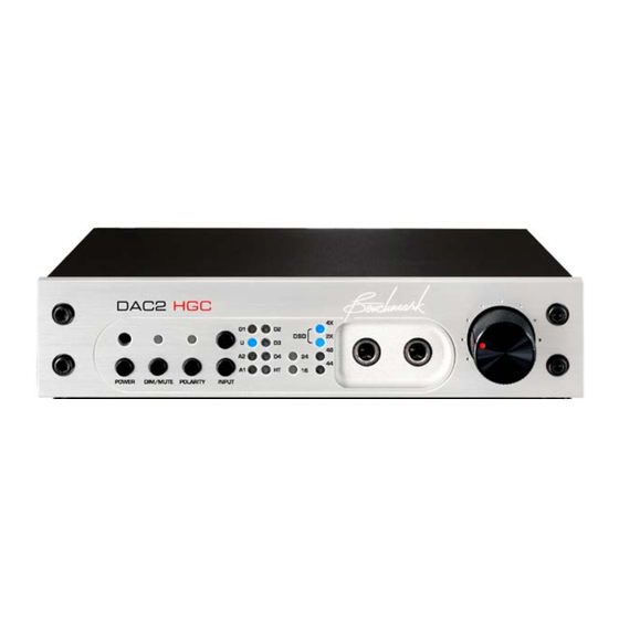
Page 1
Benchmark DAC2 HGC and DAC2 L Instruction Manual Reference Stereo Preamplifier PCM and DSD D/A Converter Asynchronous USB (Version 2.x Firmware) (Units Manufactured or Upgraded after 06/10/2016)
EQUIPPED WITH A STANDARD IEC POWER ENTRY MODULE. USE AN IEC POWER CORD THAT IS EQUIPPED WITH THE APPROPRIATE CONNECTOR FOR YOUR LOCATION. CORDS ARE AVAILABLE FROM YOUR DEALER. Instruction Manual for DAC2 HGC and DAC2 L with 2.X Firmware Page 2...
Benchmark 1-Year Warranty Jumper-Configured Options Benchmark Extended Warranty Options 64 Removing Top Cover Notes on Warranty Repairs XLR Output Pads Headphone Switch Configuration Headphone Amplifier Gain Digital PASS-THROUGH Function Instruction Manual for DAC2 HGC and DAC2 L with 2.X Firmware Page 3...
High-Efficiency Low-Noise Power Supplies – only 12-15 W, 88-264 VAC, 50-60 Hz Meets FCC Class B and CE emissions requirements Tested for immunity to radiated and conducted RF interference Instruction Manual for DAC2 HGC and DAC2 L with 2.X Firmware Page 4...
DAC1: contrast, the DAC2 cleanly reproduces all intersample peaks. • Asynchronous 192kHz USB Audio 2.0 • 32-bit D/A conversion system Word Length Display • Instruction Manual for DAC2 HGC and DAC2 L with 2.X Firmware Page 5...
Page 6
The volume control is a servo-driven analog potentiometer. This control rotates in response to commands from the remote control while providing the convenience of manual adjustments with a physical knob. Instruction Manual for DAC2 HGC and DAC2 L with 2.X Firmware Page 6...
ON button on the (programmable) remote. 1 USB input • 2 stereo unbalanced outputs • 1 balanced stereo output • 1 bi-directional 12 volt trigger • Instruction Manual for DAC2 HGC and DAC2 L with 2.X Firmware Page 7...
DAC2. Analog Selects analog input A1 and then toggles between A1 and A2. The chart at the right summarizes the functions of the IR remote control. Instruction Manual for DAC2 HGC and DAC2 L with 2.X Firmware Page 9...
If HT mode is on, the motor drive will attempt to return the volume control to the HT setting. Instruction Manual for DAC2 HGC and DAC2 L with 2.X Firmware Page 10...
A blinking blue light indicates light will blink together if the unit is that the input is selected but audio data muted while HT mode is active. is not being received. Instruction Manual for DAC2 HGC and DAC2 L with 2.X Firmware Page 11...
Page 12
This display makes it streamed in DoP format. easy to detect these processes. All Off Digital signal is not present or is not in a supported format. Instruction Manual for DAC2 HGC and DAC2 L with 2.X Firmware Page 12...
Gain-Range jumpers should be set so that comfortable listening levels occur when the volume control is set above the 11 o'clock position. Instruction Manual for DAC2 HGC and DAC2 L with 2.X Firmware Page 13...
If the volume is adjusted while DIM is active, it will not change the NORMAL setting unless the DIM volume is turned up above the last NORMAL setting. If the volume control is Instruction Manual for DAC2 HGC and DAC2 L with 2.X Firmware Page 14...
The Benchmark bi-directional 12V Trigger is compatible with virtually all In most systems, the 12V TRIGGER will be trigger systems. used to connect the DAC2 to one other Instruction Manual for DAC2 HGC and DAC2 L with 2.X Firmware Page 15...
Benchmark DAC2 or AHB2 can be used to button for three seconds. In HT mode, analog start or stop the system. inputs are passed at unity gain, and digital Instruction Manual for DAC2 HGC and DAC2 L with 2.X Firmware Page 16...
Page 17
This mode is useful disable the computer volume control (or set it in studio applications where calibrated to maximum). interface levels are used between various Instruction Manual for DAC2 HGC and DAC2 L with 2.X Firmware Page 17...
2 dB lower than the maximum systems. output level of the DAC2 (when the pads are set to 0 dB). This configuration optimizes the gain-staging between the DAC2 and the Instruction Manual for DAC2 HGC and DAC2 L with 2.X Firmware Page 18...
Add the values the frequency response at the output of the of all flashing lamps amplifier. to determine the version number. Instruction Manual for DAC2 HGC and DAC2 L with 2.X Firmware Page 19...
The 12V TRIGGER I/O is not an decoded by the DAC2. audio connection! This is a 12V DC connection for synchronizing the on and off sequencing of an entire audio system. Instruction Manual for DAC2 HGC and DAC2 L with 2.X Firmware Page 20...
Page 21
It allows a quick driverless connection to windows machines when playing sample rates of 96 kHz or less. In this mode, Windows machines can begin Instruction Manual for DAC2 HGC and DAC2 L with 2.X Firmware Page 21...
Page 22
The coaxial inputs are designed to accept either type of signal. 12V TRIGGER I/O The Benchmark bi-directional 12V TRIGGER is compatible with virtually all trigger systems. The 12V TRIGGER I/O connection Instruction Manual for DAC2 HGC and DAC2 L with 2.X Firmware Page 22...
(0 dB setting). Use the 0 dB setting with the Benchmark AHB2 power amplifier. A full description of the output attenuators and instructions for Instruction Manual for DAC2 HGC and DAC2 L with 2.X Firmware Page 23...
The DAC2 is equipped with a standard IEC power entry module. Use an IEC power cord that is equipped with the appropriate connector for your location. Cords are available from your dealer. Instruction Manual for DAC2 HGC and DAC2 L with 2.X Firmware Page 24...
To set the XLR outputs to typical professional studio levels, set the pads to 0 dB. For most home installations, set the pads to 10 dB or 20 dB. Instruction Manual for DAC2 HGC and DAC2 L with 2.X Firmware Page 25...
The right-hand headphone jack does not have a mute switch. In most cases it is convenient to have one jack that mutes the outputs and Instruction Manual for DAC2 HGC and DAC2 L with 2.X Firmware Page 26...
If the level is too low at the maximum VOLUME setting, the headphone gain is too low, and the attenuation should be decreased. Figure 5 - 10 dB Headphone Attenuation Instruction Manual for DAC2 HGC and DAC2 L with 2.X Firmware Page 27...
DAC2). By default, D4 functions as a digital input and Figure 8 - Digital PASS-THROUGH the jumpers are set according to Figure 8. Disabled (Factory Default) Instruction Manual for DAC2 HGC and DAC2 L with 2.X Firmware Page 28...
The Benchmark Rack Mount Tray mounts up to two ½-wide Benchmark products in a single race space. The tray accepts any combination of ½-wide Benchmark products (with or without rack-mount type faceplates). Instruction Manual for DAC2 HGC and DAC2 L with 2.X Firmware Page 29...
Two stereo analog inputs • drivers. Three stereo analog outputs • Two optical inputs • High-efficiency low-noise power • supplies Instruction Manual for DAC2 HGC and DAC2 L with 2.X Firmware Page 30...
Also, if the pot is manually overridden, it will interpolation process is absolutely necessary not damage the motor. to achieve 24-bit state-of-the art conversion performance. Unfortunately, inter-sample overs cause clipping in most interpolators. Instruction Manual for DAC2 HGC and DAC2 L with 2.X Firmware Page 31...
Shorts may also occur when a plug is partially inserted. Benchmark has re-invented the 12 volt trigger. The trigger connection on the DAC2 Instruction Manual for DAC2 HGC and DAC2 L with 2.X Firmware Page 32...
The balanced and Instruction Manual for DAC2 HGC and DAC2 L with 2.X Firmware Page 33...
Page 34
-144 dB relative to the level of the test tone. clock of an UltraLock2™ converter. In an Instruction Manual for DAC2 HGC and DAC2 L with 2.X Firmware Page 34...
Page 35
What UltraLock™ converters cannot do: UltraLock2™ converters cannot undo damage that has already been done. If an A/D with a jitter problem was used to create a Instruction Manual for DAC2 HGC and DAC2 L with 2.X Firmware Page 35...
The Windows driver is available at: the D/A conversion sub-system. This second asynchronous transfer eliminates any traces of jitter that accumulate as the data is BenchmarkMedia.com/dac/dac2-drivers transferred between the USB and conversion Instruction Manual for DAC2 HGC and DAC2 L with 2.X Firmware Page 36...
The DAC2 driver is available for download at: BenchmarkMedia.com/dac/dac2-drivers Before you install the driver, make sure the USB cable is unplugged. 1. In the DAC2 Driver folder, double click “setup.exe.” Instruction Manual for DAC2 HGC and DAC2 L with 2.X Firmware Page 37...
Page 38
METHOD 1 - FRONT PANEL: From the front panel, simultaneously press and hold • both INPUT buttons for three seconds (the 4X light should flash once). If the 2X light flashes instead of the 4X light, repeat this step. Instruction Manual for DAC2 HGC and DAC2 L with 2.X Firmware Page 38...
Page 39
We suggest keeping it in the default location. Click “Install”. 5. When the installation begins you will see the following screen. Please be patient while the driver installs. Installation may require several minutes. Instruction Manual for DAC2 HGC and DAC2 L with 2.X Firmware Page 39...
Page 40
You can now enjoy music over the USB Audio 2.0 connection at sample rates up to 192 kHz. DSD can also be played in DoP 1.1 format. Instruction Manual for DAC2 HGC and DAC2 L with 2.X Firmware Page 40...
The rise at 0 Hz is normal in an FFT analysis and is not an indication of noise. This 32k point FFT analysis uses a Blackman-Harris window with 16x power averaging, and spans a frequency range of DC to 32 kHz. Instruction Manual for DAC2 HGC and DAC2 L with 2.X Firmware Page 41...
Page 42
60 Hz and 180 Hz (frequencies where we would expect to see interference from the 60 Hz AC input. There is absolutely no sign of any AC hum. Instruction Manual for DAC2 HGC and DAC2 L with 2.X Firmware...
Page 43
The rise at 0 Hz is normal in an FFT analysis and is not an indication of noise. This 32k point FFT analysis uses a Blackman-Harris window with 16x power averaging, and spans a frequency range of DC to 32 kHz. Instruction Manual for DAC2 HGC and DAC2 L with 2.X Firmware Page 43...
Page 44
The rise at 0 Hz is normal in an FFT analysis and is not an indication of noise. This 32k point FFT analysis uses a Blackman-Harris window with 16x power averaging, and spans a frequency range of DC to 32 kHz. Instruction Manual for DAC2 HGC and DAC2 L with 2.X Firmware Page 44...
Page 45
This plot demonstrates the ruler-flat frequency response of the DAC2. Note that the frequency response measures - 0.01 dB at 10 Hz and -0.02 dB at 40 kHz. Instruction Manual for DAC2 HGC and DAC2 L with 2.X Firmware Page 45...
Page 46
5.1 surround system. Four DAC2 converters can be combined to form a 7.1 system. The phase accuracy between any two channels will match the phase accuracy shown above. Instruction Manual for DAC2 HGC and DAC2 L with 2.X Firmware Page 46...
Page 47
AP 2700 test set. The THD+N measurements on the unbalanced outputs confirm the effectiveness of the differential amplifiers. Similar results are obtained by measuring either side of the balanced outputs relative to ground. Instruction Manual for DAC2 HGC and DAC2 L with 2.X Firmware Page 47...
Page 48
SABRE converters. These differential amplifiers give the unbalanced outputs the ability to approach the performance of the balanced outputs. Please note that the differential amplifiers also eliminate common-mode distortion on the balanced outputs. Instruction Manual for DAC2 HGC and DAC2 L with 2.X Firmware Page 48...
Page 49
Left DAC2 - HEADPHONE - THD+N_VS_AMPLITUDE.at27 Graph 9 - Headphone Amplifier – THD+N versus Amplitude (DAC2 HGC model only) This plot shows the THD+N performance of the headphone outputs under load. Note that the THD+N performance of the headphone outputs approaches that of the balanced outputs. The DAC2 includes Benchmark's HPA2™...
Page 50
THD levels at high frequencies even when driven to 0 dBFS. Note that there is almost no rise in THD+N with frequency, even when operating at maximum output levels. Instruction Manual for DAC2 HGC and DAC2 L with 2.X Firmware...
Page 51
Note that odd harmonics are lower than the more "musical" even harmonics. Both sets of harmonics are very low in amplitude (-112 dB to -120 dB), and should be entirely inaudible. Instruction Manual for DAC2 HGC and DAC2 L with 2.X Firmware...
Page 52
The unbalanced outputs, and the headphone outputs, closely match the performance of the balanced outputs. Like Graph 11 - Even And Odd THD vs. Frequency, this plot shows THD (not THD+N). Instruction Manual for DAC2 HGC and DAC2 L with 2.X Firmware Page 52...
Page 53
Anlr.THD+N Ratio Left DAC2 - THD+N vs Sample Rate.at27 Graph 13 - THD+N versus Sample Rate The THD+N performance of the DAC2 is identical at all Sample Rates. Instruction Manual for DAC2 HGC and DAC2 L with 2.X Firmware Page 53...
Page 54
Over the entire range of the AES jitter tolerance test, the THD+N performance of the DAC2 is unchanged. The DAC2 easily passes the AES jitter tolerance test without any THD+N performance degradation. Instruction Manual for DAC2 HGC and DAC2 L with 2.X Firmware Page 54...
Page 55
Graph 4 - FFT 1 kHz. The DAC2 shows no change in performance when the AES jitter tolerance test is applied to the digital inputs. No jitter-induced sidebands are visible to a measurement limit that exceeds -140 dBFS. Instruction Manual for DAC2 HGC and DAC2 L with 2.X Firmware Page 55...
Page 56
This plot demonstrates that the DAC2 has very low IMD distortion. The 1 kHz difference frequency measures -122 dB, and the 10 kHz and 13 kHz products measure about -128 dB. IMD distortion should be well below audible levels. Instruction Manual for DAC2 HGC and DAC2 L with 2.X Firmware Page 56...
Mute on Lock Error Mute on Idle Channel 50/15 us De-Emphasis Enable Automatic in Consumer Mode De-Emphasis Method Digital IIR De-Emphasis Supported at Fs = 32, 44.1, 48 kHz Instruction Manual for DAC2 HGC and DAC2 L with 2.X Firmware Page 57...
>1.5 UI sine at 40 kHz >1.5 UI sine at 80 kHz >1.5 UI sine at 90 kHz >0.25 UI sine above 160 kHz Benchmark UltraLock2™ - all inputs Jitter Attenuation Method Instruction Manual for DAC2 HGC and DAC2 L with 2.X Firmware Page 58...
Overload Protection (independent per channel) Current limited at 300 mA, Thermal Bandwidth > 500 kHz THD+N -106 dB, 0.0005% into 30 Ohms at +18 dBu (1.26W into 30 Ohms) Instruction Manual for DAC2 HGC and DAC2 L with 2.X Firmware Page 59...
(European Union) directive 2002/95/EC, or, RoHS (Restrictions of Hazardous Substances). As of July 01, 2006, All Benchmark Media Systems, Inc. products placed on the European Union market are compliant (containing quantity limit weight less than or equal to 0.1% (1000 ppm) of any homogeneous Lead (Pb), Mercury (Hg), Hexavalent Chromium (Cr VI), and flame retardant Polybrominated Biphenyls (PBB) or Polybrominated Diphenyl Ethers (PBDE)).
In the event of failure of a product under this warranty, Benchmark Media Systems, Inc. will repair, at no charge, the product returned to its factory. Benchmark Media Systems, Inc. may, at its option, replace the product in lieu of repair.
Benchmark Extended Warranty Options The Benchmark Extended 5-Year Warranty * Benchmark Media Systems, Inc. optionally extends the standard 1-year warranty to a period of five years from the date of delivery. *For the extended warranty to become effective, the original purchaser must register the product at the time of purchase either by way of the enclosed registration card or through the product registration section of the Benchmark Media Systems, Inc.
Page 65
Benchmark Media Systems, Inc. All rights reserved. Benchmark Media Systems, Inc. Benchmark Media Systems, Inc. 203 East Hampton Place, STE 2 Syracuse, NY 13206-1633 PHONE: +1-315-437-6300 FAX: +1-315-437-8119 benchmarkmedia.com Instruction Manual for DAC2 HGC and DAC2 L with 2.X Firmware Page 65...
Need help?
Do you have a question about the DAC2 HGC and is the answer not in the manual?
Questions and answers