Table of Contents
Advertisement
Advertisement
Table of Contents

Related Manuals for Krups EF 472


Summary of Contents for Krups EF 472
- Page 1 S E R V I C E M A N U A L C O F F E E M A C H I N E Le Cube EF 472 Version 1.0 en...
-
Page 2: Table Of Contents
C O N T E N T S 1 Preface ........................ 3 2 Structure ....................... 4 2.1 Overview of the rating plates................ 4 2.2 Overview ...................... 6 2.3 Water circuit ....................... 7 2.4 Technical data.................... 8 3 Operations ...................... 9 3.1 Filling the water system.................. 9 3.2 Making a cup of coffee .................. 10 3.3 Programming the fill level................. 11 3.4 ... -
Page 3: Preface
P R E F A C E 1 P R E F A C E Please print out this The purpose of this service manual is to provide service personnel all necessary infor manual and keep it mation with regards to the correct handing, maintenance and repair of the EF 472. coffee machine together with the corre- sponding service docu- mentation. This way you This manual should be used by technicians as a valuable aid to guarantee the perma are assured to have the nent readiness of the machine.and in order to upkeep the full advantages of all the func ... -
Page 4: Structure
S T R U C T U R E 2 S T R U C T U R E 2.1 Overview of the rating plates This overview shows examples of various brands and is not complete. 4 Service Manual EF 472 ... - Page 5 S T R U C T U R E The rating plate can be found on the underside of the coffee machine, may be of very design, depending on the brand carries the following information: 1) Brand name 6) Serial number 2) Voltage and power rating 7) Machine type 3) Place of manufacture 8) Special disposal icon 4) Conform with RoHSguidelines (lead free (do not dispose with ordinary waste) solder,etc.) 9) Approval seal (CE, UL etc.) 5) Barcode 10) Article number of the rating plate Decoding the alphanumeric serial number By decoding the date of production Example: ...
-
Page 6: Overview
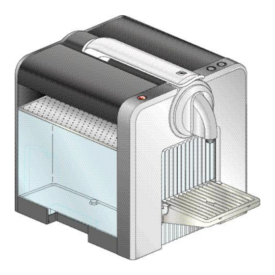
S T R U C T U R E 2.2 Overview 1) Closing handle 12) Cup tray, foldable 2) Cup cover, foldable 13) Drip tray 3) Warming plate or tray 14) Thermoblock TB 2003 (depends on model) 15) Mainboard with housing 4) Compact Brewing Unit (CBU) 16) Pump CP.04.098.0/ST/S/P 5) Capsule inlet 17) Water tank with valve, foldable 6) Flow meter 18) Connector (below the water tank) 7) "Small cup" button, back lighted 19) Connector On/Off switch 8) "Large cup" button, back lighted 20) Front cover 9) Coffee outlet 21) Support for compact brewing unit ... -
Page 7: Water Circuit
S T R U C T U R E 2.3 Water circuit 1) Water tank 5) Thermoblock 2) Water tank valve and connector 6) Compact Brewing Unit (CBU) 3) Flow meter 7) Coffee outlet 4) Pump 7 Service Manual EF 472 ... -
Page 8: Technical Data
S T R U C T U R E 2.4 Technical data Mains voltage Europe ...................... 230 V / 50 Hz USA / Canada ...................120 V / 60 Hz Japan.................... 100 V / 5060 Hz Approvals ........... SEV, CENELEC, CEconform, to UL, CUL, MITI Power ratings (for all voltages and frequencies) Thermoblock...................... 1’200 W Pump ........................70 W Performance data Heating up ..................... approx. 7.5 Wh 1 small cup ................(40 ml*) approx. 3.0 Wh 1 large cup................(110 ml*) approx. 8.0 Wh Standby operation in 1 hour ...... (without cup warmer**) approx. 13 Wh (with cup warmer**) approx. 20 Wh * Default settings ** version dependent machine function Pump ... -
Page 9: Operations
O P E R A T I O N S 3 O P E R A T I O N S 3.1 Filling the water system If the coffee machine cannot pump water although there is water in the tank, the water circuit may be empty (also refer to page 12). -
Page 10: Making A Cup Of Coffee
O P E R A T I O N S 3.2 Making a cup of coffee 1) Open the closing handle. 3) Close the handle and press it down all 2) Insert the capsule. the way. 4) Place a cup under the coffee outlet. 5) Press the "Small cup" or "Large cup" 6) When the process is completed, button. briefly open the closing handle to eject Coffee preparation starts and the used capsule. stops automatically. Should the cup start to overflow, press the same button again. 10 Service Manual EF 472 ... -
Page 11: Programming The Fill Level
O P E R A T I O N S 3.3 Programming the fill level The fill level of the cups has been pre- set by the manufacturer. Small cup ..... 40ml Large cup ... 110ml 1) Prepare coffee as usual (see "Making 2) Only release the button when the a cup of coffee" on page 10), but keep desired fill level is reached. the coffee button pressed for at least The procedure is the same for both ... -
Page 12: Emptying The Water System
O P E R A T I O N S 3.5 Emptying the water system After every opera- tion, some water remains in the coffee machine. Therefore the water system must be emptied • if the coffee machine will not be used for a long time •... -
Page 13: Light Signals
O P E R A T I O N S 3.6 Light signals The meaning of the symbols The various operat- "Small cup" "Large cup" Symbols for On/Off switch ing modes and button button occurring errors are indi- Illumination off cated by light signals (see tables). Illumination on Normal blinking Fast blinking Irregular blinking Indicators On/Off ... -
Page 14: Troubleshooting
T R O U B L E S H O O T I N G 4 T R O U B L E S H O O T I N G 4.1 Check list With an acceptance check in accord- ance with this checklist, errors are quickly found Measure / ... - Page 15 T R O U B L E S H O O T I N G Measure / Further measures / repair Check Error symptoms repair work work YES g) wiring is okay YES replace the entire elec tronics 4.2 Continuation NO replace defective cables NO continue with point 4.3 YES continue with point 4.4 4.3 Capsule container 4 Continuation is illuminated NO replace mainboard YES thermoblock is hot YES replace NTCtempera ture sensor 4.4 Both coffee buttons NO replace thermoblock are blinking 3x fast NO self test ok. Continue with point 5 YES a) water system is empty ...
-
Page 16: Repairs
R E P A I R S 5 R E P A I R S This section con- The components of the coffee machine are mostly connected with latches, meaning tains special safety without screws. and assembly notices. When loosening these connections, proceed with care and patience to avoid Disregarding them may causing any damage. lead to injuries and dam- ages. Designation of spare parts The components in the following illustrations are indexed with position numbers. The corresponding designation and spare part number are listed in section "Spare parts" on page 40. ... - Page 17 R E P A I R S 1. Remove the water tank (21), drip tray (29) with cup tray (28) and capsule container (26). 2. Open the closing handle (56) 3. Remove the coffee outlet (25). The coffee outlet is attached with two latching levers on both sides (a). Press down on both sides of the coffee outlet with your thumb and index finger and remove it (see the details). Should any problems occur, then the coffee outlet can be disassembled as follows (see Alternative disas- previous illustration): sembly of the cof- fee outlet. • Press the coffee outlet downwards until on the left side of the gap in the front panel (30) the groove (b) becomes visible. • Place the screwdriver tip in the groove, carefully pry the coffee outlet (25) loose and remove it. 4. Remove the front cover (30) : First loosen the two latching locks on the bottom. Place a screwdriver tip alternately in both slots (c) on the housing base and press hard to loosen the locking latches. Simultaneously pull out the underside of the front cover of the same side. 17 Service Manual EF 472 ...
- Page 18 R E P A I R S 5. Remove the rear panel (47) : Loosen the two screws (34) behind the housing (32). Loosen the three screws (34) on the rear panel. Press the locking latch (d) down ward with the tip of the screwdriver and remove the rear panel. 6. Remove both cup covers (17). 7. Remove the left (20) and right covers (36) : Carefully press the tip of the screwdriver in the housing opening in order to loosen the locking latch (e). Pull off the corresponding cover at the same time. 18 Service Manual EF 472 ...
- Page 19 R E P A I R S 8. Place the closing handle (56) in the vertical position and remove the cover lid (57). 9. Remove the coffee tap (24). 10. Remove the compact brewing unit (58), loosen the four screws (55) and place the compact brewing unit on one side. 11. Remove the drip tray (59) : Loosen the two locking latches on both sides (f) of the capsule bay manually. 12. Remove the cup tray or heating plate (42) (depends on machine type) : If removing heating plate, loosen the screw (3) of the grounding connection first. Push the tray or heating plate backwards until both plugs (g) are removed from the housing. Then lift it and remove backwards, diagonally. 13. Remove the side panels (39). Loosen the two screws (34) on the bottom of the housing and remove the side panels. The following function test can now be done: Function test that can be performed • "Pressure and leakage checks" on page 33 depend on the degree of disassembly.
- Page 20 R E P A I R S The following repairs can now be done: Repairs that can be done depend on the • "Replacing the compact brewing unit" on page 22 degree of disassembly. • Replace NTCtemperature sensor, see "Replacing the thermoblock, NTCtempera ture sensor and fine wire fuse(s)" on page 23. (The thermoblock can only be replaced after the compact brewing unit has been removed, see "Replacing the compact brewing unit" on page 22.) • "Replacing the flow meter" on page 26 For all other repair works the support (13) of the compact brewing unit must be loosened from the floor (32). 14. Loosen the last three screws (34) on the underside of the housing (32). 15. Use the screwdriver to carefully loosen the four locking latches (h) and to simulta neously pull the support (13) upwards. In the end, carefully move the support forward. 16. Assemble in the reverse sequence after the repair works have been completed. 20 Service Manual EF 472 ...
- Page 21 R E P A I R S Mounting tip for heating plate (depends on machine type) • Check if the two heat conductor disks (60) adhere to the heating plate (42) on the correct positions. • When assembling, make sure that the heating plate (42) with the heat conductor disks (60) is well set ont the thermoblock (5). 21 Service Manual EF 472 ...
-
Page 22: Replacing The Compact Brewing Unit
R E P A I R S 5.3 Replacing the compact brewing unit Repair tips • Remove the drip tray (59): press and loosen the two locking latches on the side (i) of the capsule bay. • In addition to the compact brewing unit (58) also replace: • the coffee tap (24) • the Oring (46) on the thermoblockhose connection • The spare compact brewing unit (58) is used in the EF 470 and EF 471 coffee machines, has therefore a longer axes protruding from the side. • Check the axial and parallel alignment of the closing handle (56) to the housing of the compact brewing unit (58). Should there be any deviations, tighten the mounting screws of the closing handle or replace a bent closing handle. 22 Service Manual EF 472 ... -
Page 23: Replacing The Thermoblock, Ntctemperature Sensor And Fine Wire Fuse(S)
R E P A I R S 5.4 Replacing the thermoblock, NTCtemperature sensor and fine wire fuse(s) Repair tips for the thermoblock • When mounting the new thermoblock (5) align the positioning holes on the bottom Check if residual water leaks from to the damping element (8). the thermoblock . Repair tips for the NTCtemperature sensor • Do not twist the NTCcable when plugging and unplugging the NTCtemperature sensor (6) : unplug the NTCplug from the main board. • Tighten the new NTCtemperature sensor (6) and spring ring (7) with a torque wrench (90 110 Ncm). Repair tips for the fine wire fuse(s) Depending on the • When mounting the safety clips (4) make sure that the housing of the fine wire fuse series, one or two (900) is positioned exactly below the safety clips. ... -
Page 24: Replacing The Pump With The Fine Wire Fuse
R E P A I R S 5.5 Replacing the pump with the fine wire fuse Repair tip for the fluid system support • Remove the fluid systems support (11) from the floor (32) : insert the tip of the screwdriver into the slits in the housing base and press and locking latches to one side. Simultaneously lift the support (11). After loosening both locking latches, tilt up the support (11) and pull it out of the anchoring on the other side. 24 Service Manual EF 472 ... - Page 25 R E P A I R S Repair tips for pump Check for water leaking from the • Always replace a defective pump (48) together with the fine wire fuse. pump. • When installing a new pump the angled hose connection (44) may have to be realigned: the white plastic Iid on the pump is rotatable and has two flat surfaces onto which the flat wrench can be placed. Mounting tip for the thermoblock • When mounting the thermoblock (5) align the positioning holes on the bottom to the damping element (8) . 25 Service Manual EF 472 ...
-
Page 26: Replacing The Flow Meter
R E P A I R S 5.6 Replacing the flow meter Repair tip for flow meters • Pull the flow meter (41) firmly upwards to remove it. 26 Service Manual EF 472 ... -
Page 27: Replacing The Mainboard With The Button Prints
R E P A I R S 5.7 Replacing the mainboard with the button prints Repair tips When installing a new electronic • Check the assembly position of the spring (14). component, the service • A label on the housing of the mainboard (35) contains specifications on the hard technician must the ware and software version. earthed with a grounding • After assembly check the plug arrangement of the mainboard (see "Wiring band. diagrams" on page 29). 27 Service Manual EF 472 ... -
Page 28: Replacing The On/Off Switch And/Or The Mains Cable
R E P A I R S 5.8 Replacing the on/off switch and/or the mains cable Repair tips • Check the assembly position of the spring (14). • Remove the insulation housing (23) : place screwdriver tip from below into the switch housing and force the switch out (62). • The onoff switch (62) has no markings for the connections. Check its switch func tions and wiring with a digital multimeter (j) and compare it with the diagram (see "Wiring diagrams" on page 29). • The cable strain relief (37) is under tension.Therefore, hold the cable strain relief with your finger when unlatching it. 28 Service Manual EF 472 ... -
Page 29: Wiring Diagrams
R E P A I R S 5.9 Wiring diagrams Diagrams for 230 V EU (first series) Diagrams for 230 V EU (valid as of 01.01.2007) 1) Print for button "On/off" 5) Pump 230 V 2) On/Off switch 6) Flow meter 3) Heating plate 7) Mainboard 230 V 4) Thermoblock 230 V 8) Print for buttons "Coffee small/large" 29 Service Manual EF 472 ... - Page 30 R E P A I R S Diagram for 120 V UL 1) Print for button "On/off" 5) Pump 120 V 2) On/Off switch 6) Flow meter 3) Heating plate 7) Mainboard 120 V 4) Thermoblock 120 V 8) Print for buttons "Coffee small/large" 30 Service Manual EF 472 ...
- Page 31 R E P A I R S Wiring diagram for 100 V Japan (first series) Wiring diagram for 100 V Japan (valid as of 01.01.2007) 1) Print for button "On/off" 5) Pump 100 V 2) On/Off switch 6) Flow meter 3) Heating plate 7) Mainboard 100 V 4) Thermoblock 100 V 8) Print for buttons "Coffee small/large" 31 Service Manual EF 472 ...
-
Page 32: Function Tests
F U N C T I O N T E S T S 6 F U N C T I O N T E S T S 6.1 Measure flow rate 1) Fill the water tank. 2) Push the connector adapter into the capsule bay. 3) Carefully close the handle, until the adapter sits firmly in the capsule cage. 4) Pull out the mount. The adapter locks with the capsule cage. ... -
Page 33: Pressure And Leakage Checks
F U N C T I O N T E S T S 6.2 Pressure and leakage checks Check the following parts of the coffee machine for leakages. • Compact brewing unit • Hose connections • Thermoblock • Pump Dangerous mains voltages and hot parts under pressure inside the coffee machine! Do not touch any parts under voltage and or hot while checking for leak ages! Always wear protective goggles. Preparations 1) Remove rear and side panels (the pump becomes visible, see "General disassembly" on page 16). 2) Push the connector adapter into the capsule bay. 3) Carefully close the handle, until the adapter sits firmly in the capsule cage. 4) ... - Page 34 F U N C T I O N T E S T S 5) Place the measuring cup under the drain hose of the pressure tester. 6) Fill and insert the water tank. 7) Connect the mains cable. Test run 8) Switch on the coffee machine. 9) After heating up, press the "Small cup" button. 10) Open the valve and let the water flow for approximately 10 sec. out of the drain hose. 11) Close the valve completely. The pres sure stabilizes after increasing briefly between 16 19 bar (pressure check). The pressure increases slowly with increasing temperature. Should the pressure exceed 23 bar, switch off the coffee machine and release the pressure by opening the valve.
- Page 35 F U N C T I O N T E S T S 12) Check all connections under pressure for audible and visible leaks. Do not run the pump for more than 50 sec. with the valve closed. 13) Switch off the coffee machine. 14) Open the valve and let water flow out of the pressure tester. 35 Service Manual EF 472 ...
-
Page 36: Measuring The Coffee Temperature
F U N C T I O N T E S T S 6.3 Measuring the coffee temperature 1) Press the onoff button. 2) Place a measuring cup under the cof fee outlet. 3) After the heating up period, press the "Small cup" button and preheat the coffee outlet for approximately 10 sec. with hot water. 4) Insert capsule (Cosi is best suited). 5) Press the "Small cup" button. 6) Wait until the measuring cup contains 20 ml of coffee. 7) Then measure the coffee temperature approx. 510 mm under the coffee out let. The coffee temperature should be 86 °C ± 3 °C (187 °F ± 5.4 °F). 36 ... -
Page 37: Maintenance
M A I N T E N A N C E 7 M A I N T E N A N C E 7.1 Descaling Only use Nespresso decalcifiers never use vinegar! Decalcifiers are aggressive to surfaces. 1) Switch off the coffee machine. 3) Remove the drip tray and capsule 2) Eject capsule. Insert the filter from the container and empty them. descaling set into the capsule bay and close the handle. 4) Reinsert the drip tray and place a 6) Switch on the coffee machine. beaker on the cup support. ... - Page 38 M A I N T E N A N C E 10) Pour the descaling solution back into 12) Empty the beaker. the water tank. 13) Remove the filter from the capsule 11) Descale again: press the "Large cup" bay. button and let the descaling solution run through the system again. 14) Thoroughly rinse the water tank and 18) Clean the coffee machine. fill it with fresh water. 15) Place the beaker on the cup support. 16) Press the "Large cup" button the pump starts. Let the entire solution in the tank run through the system. 17) Switch off the coffee machine. Descaling is completed. 38 Service Manual EF 472 ...
-
Page 39: Daily Maintenance, Cleaning
M A I N T E N A N C E 7.2 Daily maintenance, cleaning 1) Eject capsule. 2) Empty the capsule container. 3) Empty the water tank and the drip tray 7) Press the "On/Off" button. 4) Clean the water tank and the drip tray. 8) Press the"Large cup" button and rinse 5) Fill the tank with fresh water. the coffee outlet for10 sec. 6) Reassemble the coffee machine. 9) Clean the coffee machine. 39 Service Manual EF 472 ... -
Page 40: Spare Parts
S P A R E P A R T S 8 S P A R E P A R T S 40 Service Manual EF 472 ... - Page 41 S P A R E P A R T S EFR EFR Pos. Designation Pos. Designation no. no. Raised head screw, KST/PT 4x20, 30 46845 Front cover 472 alu titan, print Krups 1 44291 Torx20 46849 Front cover 472 weiss, print Turmix 2 43227 Thermoblockbracket 46867 Front cover 472 alu titan, print Turmix Raised head screw, 4x8, hexagon socket 46863 Front cover 472 alu natural,, print Magimix 3 19799 including spring ring. 46835 Front cover 472 rot, print Magimix ...
- Page 42 S P A R E P A R T S EFR Pos. Designation no. Hose FEP, 4/2,5x90 mm, pump / ther Ø 49 15821 moblock 50 42572 Hose connection, Vshaped 55° 51 37384 Holder clip, 5 mm Ø 52 43304 Angled those, silicone, flow meter / pump Hose cover, silicone, 8x1.75x125 mm, Ø 53 24971 thermoblock / compact brewing unit House PFA, 4/2.5x170 mm, Ø...
Need help?
Do you have a question about the EF 472 and is the answer not in the manual?
Questions and answers