
Related Manuals for TV One C2-7300


Summary of Contents for TV One C2-7300
- Page 1 C2-7000 S ERIES PERATION ANUAL C2-7000 Series Dual Channel Video Processor Operation Manual Version 2.9...
- Page 2 C2-7000 S ERIES PERATION ANUAL C2-7000 Series Dual Channel Video Processor Operation Manual Version 2.9...
-
Page 3: Table Of Contents
C2-7000 S ERIES PERATION ANUAL Table of Contents DISCLAIMER..................... 1 Regulatory Agency Acceptance................1 FCC Statement....................2 IMPORTANT SAFETY INSTRUCTIONS ........... 3 CAPABILITY, TERMS OF REFERENCE AND OVERVIEW SUMMARY 13 Device Capabilities .................... 13 Terms of Reference ................... 14 Device Overview....................15 Models available....................16 Input Sources ....................17 Outputs...................... - Page 4 C2-7000 S ERIES PERATION ANUAL 8.1.1 Switching an Input ..................... 36 Operating the Unit as two Independent processors..........36 8.2.1 Selecting Inputs to the Windows................36 Operating the Unit in Picture In Picture Mode (Dual PIP) ........37 8.3.1 Selecting Inputs for the Individual Windows............37 MENU TOPOGRAPHY AND ADJUSTMENT METHODOLOGY .....
- Page 5 C2-7000 S ERIES PERATION ANUAL 10.1 Connection ......................79 10.2 Communications protocol .................. 79 11.0 SERIAL / IP CONTROL SPECIFICATION..........81 11.1 Communication protocol basics................. 81 11.2 Packet format ....................82 11.3 Function list .......................84 11.4 Examples......................92 11.5 Reading and writing macros ................93 11.5.1 Reading a previously stored Macro..............94 11.5.2 Writing to a macro....................94 11.5.3 Run and Restore macros...................
- Page 6 C2-7000 S ERIES PERATION ANUAL 14.3 Application menu’s................... 123 14.3.1 File menu......................123 14.3.2 Communications menu..................123 14.3.3 Tools menu......................124 14.3.4 Resolution menu....................124 14.4 Scripting tool....................124 14.5 Image Loader ....................125 14.5.1 Loading Still Images / Testcards..............126 14.5.2 Loading Logos....................127 14.5.3 Maximum Image size – how large can my Logo / Still Image / Testcard be?..128 14.6 Resolution Editor .....................128 15.0...
- Page 7 19.8 SDI/HD-SDI Embedded Audio & Ancillary Data (C2-7200/7210/7260 only) ..140 19.9 SDI/HD-SDI Embedded Audio (C2-7300, C2-7310 only) .........140 19.10 AES3-id inputs & outputs(C2-7300, C2-7310 only) .......... 140 19.11 Audio Switching (Optional A2-2000) ..............140 19.12 Control Methods ....................140 19.13 Mechanical ......................141 19.14 Environmental....................141...
-
Page 8: Disclaimer
Immunity: BS EN 50082-1 (Generic Immunity Standard for Residential, Commercial and Light Industrial) Safety Directive: BS EN 60065:2002 (Audio/Visual Equipment Safety) C2-7300, C2-7310: Emissions: BS EN 55031-1 (Emission: Audio, video, audio-visual and entertainment lighting control apparatus for professional use) Immunity: BS EN 55031-2 (Immunity: audio, video, audio-visual and... -
Page 9: Fcc Statement
Caution: This equipment is intended for use in the manner prescribed in the Instruction Manual. Any user changes or modifications not expressly approved by TV One Multimedia Solutions could void the user’s authority to operate the equipment. Connecting this equipment to external devices requires no specially shielded cabling for FCC compliance. -
Page 10: Important Safety Instructions
2.0 IMPORTANT SAFETY INSTRUCTIONS To insure the best from this product, please read this manual carefully. Keep it in a safe place for future reference. To reduce the risk of electric shock, do not remove the cover from the unit. No user serviceable parts inside. - Page 11 2.5 Ventilation Slots and openings in the sides of the unit are provided for ventilation. To ensure reliable operation, avoid obstruction of these openings and ensure the unit is installed in a well-ventilated area. 2.6 Intellectual property Some IC chips in this product include confidential and/or trade secret property.
- Page 12 2.0 IMPORTANT: CONSIGNES DE SECURITE Afin de tirer le meilleur de ce produit, merci de lire attentivement ce manuel. Gardez-le dans un endroit sûr pour pouvoir le consulter à nouveau. Afin de réduire le risque de choc électrique, ne retirez pas l’unité de sa protection.
- Page 13 2.3 Entretien général Ne forcez pas les boutons ou connexions externes. Lorsque vous déplacez l’unité, déconnectez d’abord les connexions de ports en série puis le câble d’alimentation et enfin les câbles de connexion avec d’autres appareils. N’essayez pas de nettoyer l’unité avec des dissolvants chimiques ou des produits nettoyants en aérosol, car cela peut endommager l’unité.
- Page 14 2.0 INSTRUCCIONES IMPORTANTES DE SEGURIDAD Para sacar el mejor provecho de este producto, léase este manual con detenimiento. Guárdelo en un lugar seguro para poder hacerle referencia en el futuro. Para reducir el riesgo de calambre, no quite la cubierta del aparato. No hay piezas utilizables dentro.
- Page 15 2.3 Cuidado general No forzar interruptores o conexiones externas. Al mover el aparato, desconecte las conexiones del puerto en serie primero, luego el cable de electricidad y finalmente los cables interconectados a otros aparatos. No intente limpiar el aparato con disolventes químicos o productos de limpieza aerosol, ya que podrían dañar el aparato.
- Page 16 2.0 WICHTIGE SICHERHEITSVORSCHRIFTEN Lesen Sie diese Bedienungsanleitung bitte sorgfältig, um Ihr Produkt optimal nützen zu können, und bewahren Sie sie zum späteren Nachschlagen an einem sicheren Ort auf. Entfernen Sie bitte keinesfalls die Abdeckung, um der Gefahr eines Stromschlags vorzubeugen. Im Inneren des Geräts befinden sich keine Teile, die vom Benutzer gewartet werden können.
- Page 17 2.3 Allgemeine pflege Wenden Sie bei der Handhabung von Schaltern und Anschlüssen keine Gewalt an. Beim Umstellen des Geräts entfernen Sie zuerst die seriellen Anschlüsse, dann das Stromkabel und zum Schluss die Verbindungskabel zu anderen Geräten. Versuchen Sie keinesfalls, das Gerät mit chemischen Lösungsmitteln oder Sprayreinigern zu reinigen, da dies das Gerät beschädigen könnte.
- Page 18 2.0 BELANGRIJKE VEILIGHEIDSINSTRUCTIES Lees deze handleiding zorgvuldig door om het beste uit uw product te halen. Bewaar het op een veilige plek voor raadpleging in de toekomst. Haal nooit het omhulsel van de eenheid af, dit om de kans op een elektrische schok te verminderen.
- Page 19 2.3 Algemeen onderhoud Forceer schakelaars of externe aansluitingen nooit. Bij verplaatsing van de eenheid, de seriële poortaansluitingen eerst loskoppelen, dan de voedingskabel en als laatste de snoeren naar andere apparaten. Probeer de eenheid nooit met chemische oplosmiddelen of schoonmaakmiddelen in een spuitbus schoon te maken, omdat dit de eenheid kan beschadigen.
-
Page 20: Capability, Terms Of Reference And Overview Summary
(CORIO®2) and two video mixers for maximum flexibility in handling DVI, RGBHV, RGBS, RGsB, YUV, YPbPr, CV and YC (S-Video) signals. In addition, the C2-7200 and C2-7300 range also support SDI and HD-SDI. The C2-7300 & C2-7310 are further extended to process high quality audio data on 16 AES3-id inputs and outputs, as well as on the embedded data within the SDI and HD-SDI video signals. -
Page 21: Terms Of Reference
Dual PIP Mode - Any video input can be squeezed and placed into either of two windows of any size and positioned anywhere on the screen, even overlapping each other with user defined layer priority control. The windows can be placed over any other video input as the background. The images in the windows can then be seamlessly switched or zoomed. -
Page 22: Device Overview
layers can be positioned as desired in the ‘stack’ so that the user can create any relationship he or she desires. Modes: There are three modes of operation: Switcher, Independent and Dual Picture in Picture (Dual PIP). In Switcher mode, inputs and manipulations are shown on one output immediately and transferred to the second output when a ‘Take’... -
Page 23: Models Available
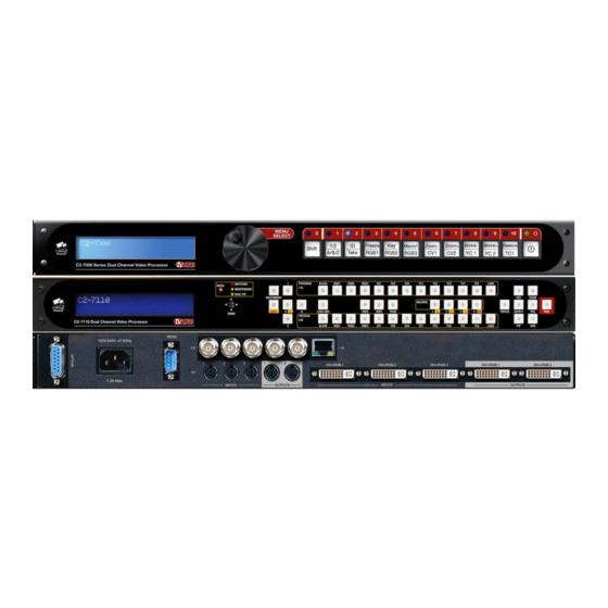
48-key non-programmable front panel. The following pictures detail the differences between the units: C2-7100 & C2-7110 front and rear panels: C2-7200 & C2-7210 front and rear panels: C2-7260 front and rear panels: C2-7300 & C2-7310 front and rear panels:... -
Page 24: Input Sources
2xDVI-I 2xCV 2xYC 2xSDI C2-7210 3xDVI-I 3xCV 3xYC 2xSDI 2xDVI-I 2xCV 2xYC 2xSDI C2-7260 3xDVI-I 3xCV 3xYC 8xSDI 2xDVI-I 2xCV 2xYC 2xSDI C2-7300 3xDVI-I 3xCV 3xYC 2xSDI 2xDVI-I 2xCV 2xYC 2xSDI + 16xAES3-id + 16xAES3-id C2-7310 3xDVI-I 3xCV 3xYC 2xSDI... -
Page 25: Layers
Window itself can be opaque, semi-transparent or invisible depending on how the various Layers, Fade levels and Keyers are set up. Within the nomenclature that follows, the Windows will be associated with one or both of the two Outputs as explained in the section detailing Modes of Operation. -
Page 26: Modes
With the exception of the color background layer, the layers can be re-ordered so that different orientations are displayed. For example, the combination shown below could be created which would mean that the Window “A” layer would have primacy over all the others: Color Background Z (Lock Source) The degree of transparency of any of the layers can be changed so that the... -
Page 27: Independent Mode
When an input selection is made, it instantly appears on Output 2––a Preview Output––but no action is taken on Output 1. The “Program” Output (Output 1) retains the last image selected when in the Switcher mode until the user presses button number 2 on the front panel. Button number 2 is the ‘Take” button when in the Switcher mode and pressing it causes the image present on Output 2 to also appear on Output 1. -
Page 28: Dual Pip Mode
3.9.3 Dual PIP Mode In the dual Picture In Picture mode, the same Lock Source (Layer Component Z) is applied to both Outputs 1 and 2. The Imagery present on those Outputs therefore will be locked to the single Lock Source even though there are two Outputs available. -
Page 29: Unpacking And Installation
1 Rack-mount Kit, 2 Ears and 8 Screws If any items are missing or defective, contact your supplier. If you are unable to resolve the problem with your supplier, contact TV One via the web at http://www.tvone.com/support for prompt replacement. -
Page 30: Functional Check
If you did not receive the correct cable, DO NOT attempt to modify the incorrect cable. Instead, immediately contact your dealer or contact TV One at the sales office nearest to your geographic location and request the proper cable. -
Page 31: Factory Reset
Power is never totally removed from the unit when it’s plugged into an active AC outlet. Pressing the button at the extreme right on the front panel only places the unit in a powered down mode. This button is a standby switch, not a true off and on switch. - Page 32 connector formerly used by the monitor cable) to the input labeled “DVI- I/RGB1” on the rear panel of the Processor. Next, take the cable from the PC monitor and connect it to the C2-7000 series’ DVI-I/RGB1 output. Then connect the AC Power Cable to a working AC outlet, turn on the PC, monitor and then the C2-7000 series.
-
Page 33: Controls And Connections
6.0 CONTROLS AND CONNECTIONS The C2-7000 series comes with one of two types of front panel: CORIO® STD – 10 button programmable. CORIO® EXP – 48 button non-programmable. 10-button programmable panel Front panel buttons 1 through 10, plus the Shift button, govern what inputs are applied to the C2-7000 series’... - Page 34 Button C2-7100 C2-7200 C2-7300 Number default default default RGB1 RGB1 RGB1 RGB2 RGB2 RGB2 RGB3 SDI1 SDI1 SDI2 SDI2 All buttons except the Shift button and Power Button can be reassigned; however, buttons “1” and “2” should not be changed since such a change will make operation of the unit via the Rotary Encoder Control more difficult.
-
Page 35: 48-Button Non-Programmable Panel
48-button non-programmable panel All 48-key front panels have the same button arrangement on the left and right sides of the front panel, with the main input selection buttons differing between units as shown below: C2-7110: C2-7210 & C2-7310: C2-7260:... - Page 36 With these front panels, you can directly select the inputs to route to the two outputs of the C2-7000 series unit. Depending on the Mode you’re in (Switcher, Independent and Dual PIP), the input selection button will have different effects: Mode PROGRAM 1/A button PREVIEW 2/B button...
-
Page 37: Inputs And Outputs
These buttons are the same on all 48-key front panels: In order to facilitate ease of use, the first two characters of every menu indicate the current Output and Window that is being adjusted; i.e. 1A = Output 1, Window A. In order to quickly change between the Window and Output under adjustment, buttons 1 &... - Page 38 System Advanced menus [Off] The above menu item must be ‘On’ to activate certain menu items. These typically control the more advanced items in the menus.
-
Page 39: Audio Inputs And Outputs
AUDIO INPUTS AND OUTPUTS C2-7000 series units with AES3 digital audio have extra connections at the rear to bring the audio in and feed the mixed & routed channels back out again. Connection summary The connectors on the rear provide the following connections: Connector: AES3-id I/O 1 AES3-id I/O 2 Inputs:... -
Page 40: Audio Outputs In Different Modes
Audio outputs in different modes The following table defines the usage of the outputs in each of the unit’s modes: Mode AES3-id I/O 1 AES3-id I/O 2 (and SDI1 output) (and SDI2 output) Switcher ‘Program’ audio output – ‘Preview’ audio output – audio audio follows the video during follows the Preview video a transition*... - Page 41 Note: in all cases, a DARS input is also available on a BNC connector. Since there are 2 AES3-id I/O connectors on the rear of the C2-7300 & C2- 7310 unit, you can mix and match up to 2 of the above A2-7300 series units.
-
Page 42: Changing The Operating Mode
DVI-I / RGB outputs.) CORIO2 C2-7100 TV One The LCD screen will display the model number when you initially apply power to the unit or perform a reset, you should make note of this number in case you require technical assistance. -
Page 43: Switching An Input
Factory Default condition. At this time, perform the Factory Reset as explained in section 5.2 above. After the system resets, the initial screen will be as follows: CORIO2 C2-7100 TV One Move to the next menu item and change it until it appears as follows: Device Mode Mode Switcher] Note: There is no Preview available in the Independent mode. -
Page 44: Operating The Unit In Picture In Picture Mode (Dual Pip)
Factory Reset as explained in section 5.2 above. After the system resets, the initial screen will once again be as follows: CORIO2 C2-7100 TV One Change the Mode to Dual PIP as shown below: Device mode Mode Dual PIP] 8.3.1 Selecting Inputs for the Individual Windows... - Page 45 Select Window A for adjustment so that the top line of the LCD display shows 1A. When you have Window A available for change, press the input button for the signal source you desire to place in Window A. This selected window can now be adjusted with the SIZE (48 key panel) or Shrink -/+ buttons (10 key panel).
-
Page 46: Menu Topography And Adjustment Methodology
9.0 MENU TOPOGRAPHY AND ADJUSTMENT METHODOLOGY From here on, we’ll be looking at the high-level menu structure employed in the C2-7000 series and, more importantly, the individual menu items that allow you to take advantage of the power of the unit. You’ll be using the Front Panel controls and the Integrated LCD Display to control the C2-7000 series. -
Page 47: The High Level Menu Structure
There are two screens that appear before the Group Menus are accessed. The first is the Banner display indicating the model of the unit: CORIO2 C2-7100 TV One Rotating the Rotary encoder clockwise (or clicking the multi-directional switch to the right) moves to the following screen: www.tvone.com... -
Page 48: Advanced Menus
Advanced menus Note that the ‘Advanced menus’ menu item must be ‘On’ to activate certain menu items. Group Names and Descriptions Menu Group Name Group Description Device mode Allows selection of switcher, independent and pip mode Adjust outputs Controls output parameters Adjust windows Controls characteristics of the pip windows Adjust keyers... - Page 49 The output resolution of the Output is defined by the setting for Output Resolution and there will be no background source visible. Genlock The output video will be “Genlocked” to the selected lock source. The output signal will be synchronous to the input sync and adjustable but there will still be no lock source visible.
- Page 50 remain in place until changed or it may be overridden by the lock mode and source. The top line of the display will show the current output resolution selected. Some units will have a limited number of output resolutions depending on their function (e.g.
- Page 51 Status Description Effect message No display There is no display attached Nothing will be output on the DVI connector. (HOTPLUG is low). Unavailable The device attached is not As the DVI output cannot be HDCP encrypted, capable of supporting then a HDCP-encrypted source cannot be HDCP.
-
Page 52: Items Associated With The Adjust Windows Group
and needs to follow a Lock source’s input – hence it should be turned Off it the CV/YC outputs are going to be used. Adjust outputs Stand. [NTSC-M/PAL-BDGHI] This menu item is only available when the Output resolution is set to PAL or NTSC. - Page 53 Adjust windows Window to adjust This menu item only appears on units with multiple windows or PIPs. It is used to select which one you want to modify. Alternatively, use one of the dedicated buttons on the front panel to choose the window to adjust. NTSC / 60Hz Source [ YC1]...
- Page 54 This allows the scaled image to be cropped at the top/bottom edges, or at the sides. Typically, this is used when performing a picture-in-picture (PIP) function (only available on certain models), where the incoming video signal has a letterbox or pillarbox size (i.e. it has black areas at the top/bottom or sides).
- Page 55 Adjust windows Aspect adjust [Simple] See later section for further details on this item. Adjust windows Temporal interp. [Off] This is a feature only present in advanced units only. It greatly improves the method of frame-rate conversion, by allowing the unit to merge frames together during the process.
-
Page 56: Extended Scaling Controls
Occasionally, it’s necessary to cause the output image to be flipped Vertically, Horizontally or both – most commonly when a video projector is ceiling- mounted, or for special effects. Adjust windows Show source label [On] Units that support source labeling have this menu item available, which allows the label to be turned on or off on a window-by-window basis. -
Page 57: Aspect Adjust' = 'Advanced
In ‘Pixel’ mode, the user has direct access to pixel and line-accurate scaling functions. This lets the user specify the exact co-ordinates and size of the source image (within the video source), and the position and size of where this is placed in the output video signal. The table below summarizes the different menu items in the different modes –... -
Page 58: Aspect Adjust' = 'Pixel
9.6.3 ‘Aspect adjust’ = ‘Pixel’ Adjust windows [ 300] , 150 750, 400 Adjust windows [ 50] , 250, 300 These menu items work together to specify the exact co-ordinates and size of the source image (within the video source) and the position and size of where this is placed in the output video signal –... - Page 59 background image can show through. The following settings allow you to vary the colour(s) that are keyed out. Adjust keyers Swap fore/backgrnd [Off] This menu item is only present on single-channel scalers – dual and quad- channel scalers have the layer priority set within the ‘Adjust Windows’ menu. This menu item allows you to swap the foreground and background images when Lock mode is set to Lock &...
-
Page 60: Edge Blend Items Within The Adjust Keyers Group
conversion) may not sample a 50% brightness as being exactly 50% i.e. sometimes 49% and sometimes 51%. Increasing the softness value will broaden the range of keyed colors so that the keying of images varies depending on how close a color is to the keyed-out range. Adjust keyers Y Key invert [Off]... -
Page 61: Items Associated With The Adjust Logos Group
This controls the blend width and height respectively. Left and Right blend sizes are adjusted together by the first number, and Top and Bottom blend sizes are adjusted together by the second number. Adjust keyers E.blnd gam. [1.00] x [1.00] This controls the gamma for the blend width and height respectively. -
Page 62: Items Associated With The Adjust Borders Group
Adjust logos Logo number A fixed number of Logos can be stored in non-volatile memory for later recall. Use this setting to select the Logo to be displayed and adjusted. Adjust logos H/V position % [10] [10] This parameter controls the position of the logo within the window as a percentage of the total size of the screen –... -
Page 63: Items Associated With The Adjust Sources Group
Adjust borders Brdr size H/V This adjustment allows the height and width of the border to be changed it can be up to 255 pixels thick. Adjust borders Brdr offset H/V This allows the border to be offset from the window. A typical application is the creation of a drop shadow effect. -
Page 64: Menu Items Common To All Inputs
made using the following operating parameters will only apply to the selected input. Selection of a CV/YC source will reveal different menu items that allow adjustments beyond those used for RGB sources. The menu discussions that follow relate first to RGB sources, then to CV / YC type sources. 9.11.1 Menu items common to all inputs Source: RGB1 Aspect correct... - Page 65 signal on an input, or to eliminate any undesired noise at the top or bottom of a PAL or NTSC video source. Source: RGB1 Audio input source [ 1] If your unit has an internal audio switcher / selector, this menu item selects the desired Audio input for use with the active video source, allowing an audio-follow-video function.
- Page 66 Source : RGB1 De-int [M.comp med] An interlaced input consists of two fields separated in time. Both fields are required in order to make up the full resolution input image, but since they are sent one after the other, a moving image will have “motion artifacts” if the two fields are simply combined together.
-
Page 67: Dvi Source Menu Items
9.11.2 DVI Source Menu Items Source: DVI1 HDCP [Inactive] [Off] HDCP is supported on certain units only - and only on the DVI input connector. This menu item lets you change whether HDCP is active on this particular DVI input. If turned ‘Off’, then a source that requires HDCP encryption will not send a video signal to your unit. - Page 68 EDID Usage Mem1 Mem2 User-definable – see ‘EDID capture’ Mem3 Mem4 Mem5 Mem6* HDMI* Default HDMI EDID data for your unit Default DVI EDID data for your unit The attached monitor’s EDID data *Your unit will have either Mem6 or HDMI, but not both. If you change this value, you’ll need to store your settings and then re-boot the CORIO2 unit at least once to ensure that the source sees that the EDID data has changed.
-
Page 69: Rgb Source Menu Items
9.11.3 RGB Source Menu Items Source: RGB1 Autoset status [Inactive] Once the Autoset sense setting has been made, this menu item is accessed and activated. The Autoset sense utility will then correct the pixel phase and then position the Top Left portion of the image and the Bottom Right portion of the image. -
Page 70: Cv & Yc Source Menu Items
9.11.4 CV & YC Source Menu Items Of the above Source Menu items, the Autoset sense and Autoset status functions, RGB type and Pixel phase are specific to RGB signals only. The rest of the Source menu items function with RGB, CV or YC type signals. In addition, there are four additional Menu items that are only used with CV or YC type signals and these are explained below: Source: YC1... -
Page 71: Items Associated With The Adjust Audio Group + Other Digital Audio Adjustments
Used to select the image from memory to use as a source for the SIS / TC source currently selected. Dedicated software can be used to upload user- defined images – see our website. 9.12 Items Associated with the Adjust audio group + other digital audio adjustments This section only relates to units that support built-in digital audio processing. - Page 72 The AES3 outputs are active at all times. If the output is an SDI standard (e.g. NTSC or 720p), then your unit will also embed the audio data into those outputs as well. High quality sample-rate conversion is used to allow mixing of multiple non-synchronous audio sources without noticeable degradation of the audio quality.
-
Page 73: Extra Item In Adjust Outputs
In Independent mode, the above diagram would change slightly, to show a second set of 8 outputs (1A and 2B). Both sets of outputs have access to the full number of audio inputs. In Dual PIP mode, the above diagram accurately represents the processing that is performed. -
Page 74: Extra Item In Adjust Sources
In Dual PIP mode, A, B and Z are all definable (if Lock&Mix is active) – thus 3 audio sources will be mixed together. The mixing is done via addition, so volume levels should be borne in mind. This single volume / mute selection controls all 8 audio channels being processed for this window. -
Page 75: Items Associated With The Adjust Transitions Group
Adjust audio Delay adjust 0] ms This controls the audio delay that will be present for this audio source. This is a global control that controls the audio delay wherever this audio source is used – even if by multiple windows. Note that the unit automatically calculates the delay for the video source processing, and accounts for this in the audio delay. -
Page 76: Items Associated With The Adjust Buttons Group
Down/Up (Bottom to Top). ‘Wipe’ also supports: Diagonal and Diamond effect. Adjust transitions Wipe size [100] Wipe Size sets the ‘granularity’ of the ‘Wipe’ effect and so is only shown when ‘Wipe’ is the transition type. The smaller the number, the more elements there are to the wipe. -
Page 77: Items Associated With The Adjust Ethernet Group
Adjust buttons CC-300 btn [ 1] This menu lets you change the assignment of each button on an attached CC- 300 unit. If you have multiple CORIO2 units attached to a CC-300, then it is advisable to set them all so that their buttons act in the same way for all units 9.15 Items associated with the Adjust ethernet group (Please note that not all units have this sub-menu.) - Page 78 The sub-network’s ‘sub-net mask’ then needs to be copied to the ‘IP sub’ menu item listed below. For simple setups (where only a single sub-network is in use), there is no need to change the IP gtwy (gateway) numbers. Adjust ethernet IP enabled [Auto] This parameter has three possible states: On, Off and Auto.
-
Page 79: Items Associated With The Adjust Resolutions Group
Certain units require a re-boot once the new IP address has been entered. Once activated, all current settings (including other menu items) will be saved and the unit will re-boot. If you do not see this menu item, then your unit has already implemented your changes and no re-boot is required. - Page 80 800 x 600 60 Hz Interlaced [ Off] This adjustment specifies whether the image is interlaced or progressive scan. It toggles simply On or Off, so there are no flashing brackets. 800 x 600 60 Hz H.freq.crse [37.879] kHz Course Frequency Adjust The H freq.crse (Horizontal Sync Frequency - Course) adjustment provides the option for changing the Horizontal Sync timing Frequency in 100 Hz steps.
- Page 81 The well-known 800 x 600 computer resolution standard simply means that there are 800 pixels/line visible horizontally and there are 600 lines visible vertically. This item provides a way to change the number of active pixels and lines. 800 x 600 60 Hz H/V Start [ 88] x 23 There is a period of time between the end of the Horizontal Sync pulse and...
-
Page 82: Items Associated With The System Group
+H-V -H-V 9.17 Items Associated with the System group The final Sub Menu is for adjustments of System parameters. The “System” in this case means the unit’s functions that are generally unrelated to individual inputs, outputs or any of the various production features. System SW: 16, PT: 12,... - Page 83 System Push to store This screen provides a quick and easy way to store all current operating parameters. The unit will remember the set up you are currently using at the time of data storage and also when you next apply power. To store the current settings, press and release the control button.
- Page 84 System Serial type [RS-232] This menu item controls the type of serial port in use on certain units (not all units support this feature). Options available are RS-232, RS-422 and RS- 485. The default is RS-232. System RS232 baud rate [57600] This menu item allows the adjustment of the serial baud rate used for RS-232 communications.
- Page 85 System Power cycles Power Cycles refers to how many times the unit has been powered since it left the factory. This is an informational screen. No action is taken regardless of the value shown here, however some users have an equipment cleaning or specification audit procedure and this information may be useful to those users.
-
Page 86: Serial Port
10.0 SERIAL PORT 10.1 Connection Your unit is fitted with a standard ‘D9’ plug or socket allowing it to be controlled from a computer or other type of terminal or console with a similar interface. Most computers fitted with an RS232 port, known as a ‘COM’ port, will have a ‘D9’... - Page 87 Note: Any command you send to the unit will be replied to either with an error code or with the actual changed value. This may be different to the one you sent; for example, if trying to set a value too high or too low.
-
Page 88: Serial / Ip Control Specification
11.0 SERIAL / IP CONTROL SPECIFICATION PLEASE NOTE: Not all units support Serial and/or IP (Ethernet) communications – check to see if this feature is present on your unit. This section outlines how to control a unit via a Serial or Ethernet link (if fitted to your unit), using ASCII-based commands. -
Page 89: Packet Format
The ACK flag will be returned as 0 if the command is invalid for some reason – for example a bad FUNCTION, WINDOW, OUTPUT or PAYLOAD value. An ACK=0 message will be otherwise identical to the one you sent, so you know exactly which message has the error. - Page 90 Bit 6 = ACK bit. Should be set to 0 for messages to the unit. ACK=1 returned means message was okay. ACK=0 returned means an error was present in the message. Bit 5 = 0 Reserved for future use. Bit 4 = 0 Reserved for future use. Bit 3 = 0 Reserved for future use.
-
Page 91: Function List
ASCII-hex byte that is the (check) sum of all previous bytes (excluding the SOP 'F' character). E.g. The command F0400410082000001C8 has the checksum of 04+00+41+00+82+00+00+01=C8, so the complete command to send is F0400410082000001C8. A short-cut for debugging allows the checksum to be replaced by 2 question marks, so in the previous example you could send F0400410082000001?? Instead. - Page 92 Preset store Set to 1 to store – automatically resets to 0. Preset erase Set to 1 to erase – automatically resets to 0. Adjust outputs Output enable 0=Blanked, 1=Active Lock source (connector) 0x10 to 0x1F = RGB1 to RGB16 0x30 to 0x3F = CV1 to CV16 0x40 to 0x4F = YC1 to YC16 0x50 to 0x5F = SDI1 to SDI16...
- Page 93 3 = 14:9 Letterbox top 4 = 16:9 Letterbox centre 5 = 16:9 Letterbox top 6 = >16:9 Letterbox centre 7 = 14:9 Full format 8 = 16:9 Full format Take 0->1 = Perform a Preview -> Program transition Audio amp. Volume -16 to 15 AES/SDI Chan.
- Page 94 In (top-left H) In (top-left V) In (H size) In (V size) Out (top-left H) Out (top-left V) Out (H size) Out (V size) Aspect change 0..2 = Normal, Letterbox, Pillarbox Aspect adjust 0..1 = Simple, Advanced Flicker reduction 0..3 = Off, Low, Med, High Image smoothing 0..2 = Off, Med, High Image flip...
- Page 95 E.blnd size V 0.. limited by V height E.blnd gamma H 1..150 1=0.01, 150=1.50 E.blnd gamma V 1..150 1=0.01, 150=1.50 E.blnd comp cent 0..99 E.blnd comp side 0..99 Logos (on certain models only) Logo enable 0..1 = Off, On Logo number 0..9 Logo selection H/V out shift (H) 0..100 %...
- Page 96 Label H. Position 10..5F 24D 0..3 (Off / Left / Center / Right) Label V. Position 10..5F 24E 0..3 (Off / Top / Middle / Bottom) Label char. to adj. 10..5F 24B 0..23 Label char. value 10..5F 24C 32..127 EDID to use 10..1F 243 0..7 to specify EDID entries 1..Mon EDID capture entry#...
- Page 97 Noise reduction 10..5F 23F 0..1 = Off, On Bright 30..5F 0BB 0..180 Contrast 30..5F 0BC 0..180 Saturation 30..5F 0B9 0..180 30..5F 0BA -180..180 Sharpness 30..5F 080 -7..+7 Luma delay 30..5F 0BD -4..3 Field swap 10..FF 0C9 0..1 = Off, On (swaps odd/even fields) Field Offset 10..FF 196 0..7 = -4..+3 (defaults to 4 = 0)
- Page 98 Adjust resolutions Note: You MUST set the 'Image to adjust' value to the correct value first, and only then change the other values - otherwise you may be adjusting the wrong entry. The user should not adjust the 'Image to adjust' entry using the front panel whilst also accessing it via RS232 Image to adjust 1..1000...
-
Page 99: Examples
Fan speed (rpm) Read only Led brightness 0..100 LCD backlight 0..1 = Off, On Serial type 0 = RS-232 (See Specs to see if your 1 = RS-422 unit supports all options) 2 = RS-485 RS232 Baud rate 0..6 = 9600, 19200, 28800, 33600, 38400, 57600, 115200 TAC number 0 Read only... -
Page 100: Reading And Writing Macros
000001 ?? CR 000001 8A CR Set 1A Shrink to 110 – invalid max for shrink is 100 00006E ?? CR 000064 70 CR Read 1C Zoom level – invalid as window C does not exist ?? CR 000000 CD CR Read 1B Zoom level Zoom = 100 ?? CR... -
Page 101: Reading A Previously Stored Macro
11.5.1 Reading a previously stored Macro In order to read a macro the following commands must be sent in this specific order – no other commands should be sent between these messages. The CHA in these cases relate not to the source but to the macro we are reading. Packet sent Packet returned SOP CMD CHA WIN OUT FUN PAY CS EOP... -
Page 102: Run And Restore Macros
11.5.3 Run and Restore macros Macros once programmed can be run by sending one of the following commands. By running macro 5 the unit can be restored to its previously saved state, when used in conjunction with the other macros this allows a default setup or baseline for the unit to be created. - Page 103 Select YC3 as source 000208 Select TC1 / SIS1 as source 000209 Select TC2 / SIS2 as source 00020A Select OUT1 as source 00020B Select OUT2 as source 00020C Toggle window A/B/Z 00020D Toggle output 1/2 00020E TAKE (activate transition) 00020F FREEZE 000211...
- Page 104 Erase Macro 4 28011C Erase Macro 5 28011D Erase Macro 6 280167 Erase Macro 7 280168 Decrease Horizontal Pan value 00021E Increase Horizontal Pan value 00021F Decrease Vertical Pan value 000220 Increase Vertical Pan value 000221 Select window A 000223 Select window B 000224 Select window C...
- Page 105 Select SDI5 as source for window A 000273 Select SDI6 as source for window A 000274 Select SDI7 as source for window A 000275 Select SDI8 as source for window A 000276 Select DVI1 as source for window B 00022D Select DVI2 as source for window B 00022E Select DVI3 as source for window B...
- Page 106 Select UNI7 as source for window A 000287 Select UNI8 as source for window A 000288 Select UNI1 as source for window B 000289 Select UNI2 as source for window B 00028A Select UNI3 as source for window B 00028B Select UNI4 as source for window B 00028C Select UNI5 as source for window B...
-
Page 107: Reset Command
E.g. to Load Preset 1, use the text string: F041041024F000291??<CR> 11.5.5 Reset command This is a special command to reset a unit (as if power had been removed and re-applied). Note that unlike the above commands, this is sent as binary (i.e. not as ASCII text). -
Page 108: Common Operations
12.0 COMMON OPERATIONS This section provides step by step instructions for some common operations for the C2-7000 series. 12.1 Operation of the Keyer The C2-7000 series has a very powerful Luminance and Chroma keyer and can key on Window “A”, Window “B” and Window “Z” independently. The listing that follows breaks the Keyer operation down to a series of steps that are defined by Operational Mode. - Page 109 The Key Min/Max may need to be readjusted after making the softness adjustment. Touch up any of the previous settings to get a clean key. At this point, only the key color should be transparent. Adjust Max Fade Level to change the transparency of the overlay. ...
- Page 110 Decrease V Key Min until reappears, then increase until it disappears again. If the edges appear rough, increase the V Key softness. The Key Min/Max may need to be readjusted after making the softness adjustment. Touch up any of the previous settings to get a clean key. ...
- Page 111 Dual PIP Mode Method (One or Two Key Channels, Locked) Change mode: Change Mode to Switcher Setup the lock source Enter Adjust Outputs menu. Select Output 1. Set Lock to Lock & Mix. Set the lock source to be a valid Input source Set Output Type to desired setting Setup first key source: ...
- Page 112 The Key Min/Max may need to be readjusted after making the softness adjustment. Touch up any of the previous settings to get a clean key. At this point, only the key color should be transparent. Adjust Max Fade Level to change the transparency of the overlay. ...
-
Page 113: Creating A Macro
12.2 Creating a Macro On the 10-key front panel units, you can store up to 5 macros and associate them with 5 different buttons of your choosing. It is also a good idea to assign another button to the Restore function. This restore function allows the unit to be returned to it previously saved state, thus allowing you to toggle between a preset condition and this saved state. -
Page 114: Standards Conversion - Ntsc To Pal
Press and hold the macro button (using SHIFT if needed) until the unit gives a short beep and the display says Info: Added to Macro. This has now added the Shrink position for window 1A to the macro The macro is now complete. Pressing your RESTORE button will return the unit to the last saved state. -
Page 115: Edge-Blending Setup
This guide is intended to summarise how to setup such projectors when used with a suitable number of TV One’s CORIO®2 scaling engines. The C2-7000 series are dual processors and therefore require only a single unit to perform... -
Page 116: Edge-Blending Requirements
S-curves for left and right projectors, with edges blended. S-curves, when properly overlapping, will add together to result in full brightness. 13.2 Edge-blending requirements To obtain the best edge-blending results, you will need: 1. A perfectly flat projection screen. This is vital, or it will not be possible to perfectly align your two projected images with each other. -
Page 117: Basic Setup Of The Two Projectors
13.3 Basic setup of the two projectors Basic video projector setup showing overlap. The above diagram shows how the two projects should be placed to create a wider than normal image. The amount by which they overlap is very important, as this will also relate to the zooming values to be used for each of the CORIO®2 scaling engines. -
Page 118: Initial Setup
For use with dual-channel scalers such as the C2-7000 series, connect your video source (e.g. a DVD player or computer) to an input on the C2-7000 unit. It is not necessary to feed two signals – the C2-7000 unit can use the same signal for both outputs. -
Page 119: Edge-Blending Activation
around 10% to 20% overlap are usually around 180%. In other words, not quite 2x zooming (since that would give no overlap at all). Figure ‘a’ shows the original image and ‘b’ shows the two zoomed images. Note that the two images are at different ‘Pan’ positions – i.e. they are zoomed into different areas of the image –... -
Page 120: Edge-Blending Guide Lines
There is a formula for calculating the edge blend size (E) from the zoom value (Z) and horizontal pixel width of the output (H): E = 2 * H * (1 – Z/200) [pixels] For example, with zoom (Z) at 190%, output resolution of 1024x768 (H=1024), we can calculate E as: E = 2 * 1024 * (1 –... -
Page 121: Alignment Of Projectors
blending. (G marks the green lines, R marks the red, Y marks the yellow, for those reading in black and white.) Outputs 1 and 2 with guide lines shown. G R R G Outputs 1A and 2B partly overlapping. Outputs 1A and 2B perfectly overlapping – the red and green lines turn to yellow when aligned together. - Page 122 Too far apart – you need around 15% overlap, such that the red and green lines overlap. Offset – make sure your projectors are perfectly G R R G aligned both horizontally and vertically. Key-stoning – ensure your projectors have the same keystone values, to...
-
Page 123: Gamma Correction
Perfect alignment – your red and green vertical lines should overlap to produce yellow ones. 13.10 Gamma correction By now you should have two perfectly aligned projectors, but possibly with a brighter than normal overlap. This is most probably because a projector’s luminance is not perfectly linear and therefore will need to have what’s called ‘gamma correction’... -
Page 124: Aspect Ratio Adjustment
when you’re trying to output black, there will be a ‘hot area’ where the two projectors are now overlapping, of twice the projector’s ‘black level’ output. The solution is to adjust the ‘Eb comp cent’ value (the first in the ‘Eb comp cent/side’... -
Page 125: Other Setup Approaches
1. Either use a 2 output from the unit with Output 1, or a distribution amplifier to generate a 2 identical signal. Feed this into RGB1 on the unit handling Output 2. 2. Go to ‘Adjust outputs’ for Output 2 3. - Page 126 E.blnd H 640x480 800x600 1024x768 1280x720 1280x1024 1600x1200 1920x1080i...
-
Page 127: Windows Control Panel
14.0 WINDOWS CONTROL PANEL A powerful utility is available for the C2 product range and can be downloaded from our support web site or found on the Product CD (where supplied). To install the application click on the setup file and follow the on screen instructions. -
Page 128: Connecting To A Unit
In the Ethernet section be sure to set the IP address to the same as the address you have set on the unit (units Ethernet menu). The port number used should also reflect the port number on the unit. If there are multiple units on the network then this port number should be the same for all units, only the IP address must be unique. - Page 129 Figure 4 Detecting a unit Once the application detects and connects to a unit you will be asked if you wish to “synchronize with the unit”, this will read all the settings from the connected unit and update the application. Figure 5 Synchronize application Once synchronized any changes made on the unit or on the application will be reflected on the unit and the application.
-
Page 130: Application Menu's
14.3 Application menu’s 14.3.1 File menu Figure 6 File menu Across the top of the application are the toolbar menu options. The first menu item is File within this menu you can Save and Load previous setups into the application, these setups contain all the settings of the unit. Following a Load the application will ask if you would like to synchronize the unit, if you do not synchronize then the unit and the application will show different values. -
Page 131: Tools Menu
The Program Resolutions menu will program the resolutions into the unit as defined on the resolutions Tab. The Program Settings menu will program all adjustments into the unit 14.3.3 Tools menu Figure 8 Tools menu The tools menu provides access to the scripting tool, image loader and show settings. -
Page 132: Image Loader
Figure 10 Scripting button screen Up to 24 buttons/functions can be defined, and each of these buttons/functions can perform multiple actions. Figure 11 Script editor In order to edit or create a script select Script->Edit from the menu, this will then present the script editor as shown above. -
Page 133: Loading Still Images / Testcards
14.5.1 Loading Still Images / Testcards Figure 12 Image loader To program a Still Image / Testcard into the unit select the ‘Testcards’ tab from the image programmer screen and then press Load Image. You can select JPEG, BMP and GIF images. The image will be loaded and shown on the screen. -
Page 134: Loading Logos
14.5.2 Loading Logos Figure 13 Logo Loader To program a logo into the unit select the ‘Logos’ tab from the image programmer screen and then press Load Image. You can select JPEG, BMP and GIF images. The image will be loaded and shown on the screen. -
Page 135: Maximum Image Size - How Large Can My Logo / Still Image / Testcard Be
14.5.3 Maximum Image size – how large can my Logo / Still Image / Testcard be? The image size for a Logo or Still Image / Testcard is limited by the amount of memory available in the unit; this is approximately 128kbytes of compressed image for a Still Image / Testcard and approximately 32kbytes for a Logo. - Page 136 There are 2 ways to create a resolution using this tool. The easiest, shown on the New resolution tab at the side, allows you to create a new resolution using the minimum information of Horizontal and Vertical size and the desired refresh rate.
- Page 137 Figure 16 Add resolution to table Once your new resolution is added, you can program the resolution into the Scaler using the Communications menu and then selecting Program into unit and then selecting Program Resolutions. The application will proceed to program all the resolutions on the list into the scaler. Note that this will overwrite any resolutions currently in the scaler.
- Page 138 Figure 17 Resolution editor - advanced timings In order to modify an existing resolution simply click on the resolution table at the bottom of the screen and it parameters will be editable within the Timings tab. Once the edits are complete click on Update to modify the settings for the selected resolution or Create New to keep the selected resolution and create a new resolution with modified parameters.
-
Page 139: Troubleshooting And Technical Support
15.0 TROUBLESHOOTING AND TECHNICAL SUPPORT If problems are experienced, please read through the symptom topics below in order to resolve the problem. After doing so, if you still need to, contact Technical Support at http://www.tvone.com/support. Please have the following details of the problem handy: Whether the problem happens only at specific times or has only just started occurring (and what other things have changed at the same time). -
Page 140: There Is Excessive Flicker On The Output
15.4 There is excessive flicker on the Output. Try using a different Flicker reduction mode. Turning the contrast down and the brightness up on the output device can have a large effect on flicker. Or try adjusting the brightness and contrast of the source input by selecting the Input adjust menu. -
Page 141: The Rgb Input Is Selected But The Image Is Rolling Or Pink
15.11 The RGB input is selected but the image is rolling or pink. Check the Adjust sources menu and confirm that the input type and sync method is set correctly. (Having YUV input selected, instead of RGBHV often causes this problem). 15.12 The video signal from my DVD player does not appear to work. -
Page 142: Return Procedure
16.2 To return a unit for repair First contact TV One using the http://www.tvone.com/support website. Support personnel will determine whether a return to the factory is the appropriate solution. If that’s the case, a Return Authorization Number will be issued. - Page 143 Please clearly state the return number on the outside packaging and on any accompanying documentation. This will greatly speed up processing. IMPORTANT: DO NOT return a unit for warranty repair without first obtaining a Return Authorization Number. No action will be taken on a unit returned in warranty for repair without a Return Authorization Number...
-
Page 144: Warranty Policy
The liability of TV One with respect to any defective products will be limited to the repair or replacement of such products. In no event shall TV One be... -
Page 145: Connector Pinouts
18.0 CONNECTOR PINOUTS 18.1 DVI-I connector PIN# SIGNAL PIN# SIGNAL T.M.D.S DATA 2- HOT PLUG DETECT T.M.D.S DATA 2+ T.M.D.S DATA 0- T.M.D.S DATA 2/4 SHIELD T.M.D.S DATA 0+ Not used T.M.D.S DATA 0/5 SHIELD Not used Not used DDC CLOCK Not used DDC DATA T.M.D.S CLOCK SHIELD... -
Page 146: Specification
19.0 SPECIFICATION 19.1 Video Inputs Composite Video 3 x via BNC Connector S-Video (Y/C) 3 x via 4-PIN Mini-DIN Connector DVI-I 3 x via DVI-I Connector (DVI-I = DVI-D / RGB / YUV) C2-7200/7210/7300/7310: SDI or HD-SDI 2 x via BNC Connector C2-7260: only 2 of the 8 SD/HD-SDI inputs can be used simultaneously. -
Page 147: Input Rgb Sync
SDI/HD-SDI Embedded Audio (C2-7300, C2-7310 only) Full embedded audio support for inputs & outputs at 48kHz. >100dB quality digital sample-rate convertor. 19.10 AES3-id inputs & outputs(C2-7300, C2-7310 only) Support for 44.1 / 48 / 96kHz AES3-id input. AES3-id output at 48kHz. -
Page 148: Mechanical
19.13 Mechanical Desktop Case (HWD) 1.725” x 17” x 7.92” (44x431.8x201.2mm) With Rack Ears (HWD) 1.725” x 19” x 7.92” (44x482.6x201.2mm) Weight (Net) 7lbs 1oz (3.2kg) 19.14 Environmental Operating Temperature 0° to +45° C (+32° to +113° F) Operating Humidity 10% to 85%, Non-condensing Storage Temperature -10°... -
Page 149: Contact Information
20.0 CONTACT INFORMATION Should you have and questions or require assistance with this product in areas not covered by this manual, please contact TV One at the appropriate location shown below: TV One USA TV One Europe 2791 Circleport Drive...
Need help?
Do you have a question about the C2-7300 and is the answer not in the manual?
Questions and answers