Table of Contents
Advertisement
SPLIT-TYPE, HEAT PUMP AIR CONDITIONERS
SERVICE MANUAL
Wireless type
Models
MSZ-A09RV -
MSZ-A12RV -
MUZ-A09RV -
( WH )
E1
MUZ-A12RV -
( WH )
E1
CONTENTS
1. TECHINICAL CHANGES ··································2
2. PART NAMES AND FUNCTIONS······················4
3. SPECIFICATION·················································6
4. NOISE CRITERIA CURVES ·······························8
5. OUTLINES AND DIMENSIONS ·························9
6. WIRING DIAGRAM ··········································10
7. REFRIGERANT SYSTEM DIAGRAM ··············12
8. PERFORMANCE CURVES ······························13
9. MICROPROCESSOR CONTROL ····················23
10. SERVICE FUNCTIONS·····································38
11. TROUBLESHOOTING ······································40
12. DISASSEMBLY INSTRUCTIONS·····················57
13. PARTS LIST······················································61
14. OPTIONAL PARTS···········································65
1999
No. OB230
E1
E1
Advertisement
Table of Contents

Related Manuals for Mitsubishi Electric MSZ-A09RV-E1


Summary of Contents for Mitsubishi Electric MSZ-A09RV-E1
-
Page 1: Table Of Contents
1999 SPLIT-TYPE, HEAT PUMP AIR CONDITIONERS No. OB230 SERVICE MANUAL Wireless type Models MSZ-A09RV - MUZ-A09RV - ( WH ) MSZ-A12RV - MUZ-A12RV - ( WH ) CONTENTS 1. TECHINICAL CHANGES ··································2 2. PART NAMES AND FUNCTIONS······················4 3. SPECIFICATION·················································6 4. NOISE CRITERIA CURVES ·······························8 5. -
Page 2: Techinical Changes
TECHNICAL CHANGES INFORMATION FOR THE AIR CONDITIONER WITH R-410A REFRIGERANT • This room air conditioner adopts R-410A of HFC refrigerant which never destroys the ozone layer. Pay attention following points. 1 As R-410A working pressure is 1.6 times higher than that of R-22 of previous refrigerant, dedicated tools and piping are required. - Page 3 Conversion chart of refrigerant temperature and pressure (MPa.G) R-410A R-22 NOTE : The unit of pressure has been changed to MPa on the international system of units(SI unit system). The conversion factor is: 1(MPa • G) =10.2(kgf/f f • G) -0.5 -30 -20 -10 1.Tools dedicated for the air conditioner with R-410A refrigerant...
-
Page 4: Part Names And Functions
2 Optional extension pipe for R-410A ([6.35/[9.52) MAC-A00PI ([6.35/[9.52) MAC-A01PI ([6.35/[9.52) MAC-A02PI ([6.35/[9.52) MAC-A03PI ([6.35/[9.52) MAC-A04PI 3.Refrigerant oil Apply the special refrigeration oil (accessories) to the flare and the union seat surfaces. 4.Air purge Use the vacuum pump for air purging for the purpose of environmental protection. 5.Additional charge For additional charging, charge the refrigerant from liquid phase of the gas cylinder. -
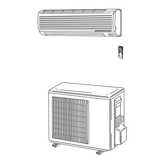
Page 5: Outdoor Unit
MUZ-A09RV- MUZ-A12RV- OUTDOOR UNIT Air inlet Piping Drain hose Air outlet Drain outlet MSZ-A09RV- MSZ-A12RV- REMOTE CONTROLLER Signal transmitting section Operation display section CLOCK 6 00 1 1 00 OPERATE /STOP (ON /OFF)button ON/OFF COOL WARM OPERATION SELECT button TEMPERATURE buttons MODE I FEEL COOL DRY HEAT VANE... -
Page 6: Specification
SPECIFICATION Indoor model MSZ-A09RV - MSZ-A12RV - Function Cooling Heating Cooling Heating Single phase Single phase Power supply 220-240V,50Hz 220-240V,50Hz Capacity 2.6 (0.9-3.3) 3.6 (0.9-4.8) 3.4 (0.9-3.8) `4.8 (0.9-6.1) K /h Air flow(Hi) Capacity Dehumidification — — Power outlet Running current 3.67-3.37 4.55-4.17 5.60 - 5.13... -
Page 7: Indoor Unit
Specifications and rating conditions of main electric parts INDOOR UNIT MSZ-A09RV Model Item MSZ-A12RV 1.5+ 440V Indoor fan capacitor MP24GA 12V 300" Vane motor ERZV10D471 Varistor (NR11) S201DH1Y Semiconductor relay Terminal block JM1aN-ZTMP-DC12V Relay (compressor) (52C) 93.5:5A 250V Terminal block thermal Fuse 136:i3: 2A Indoor fan motor thermal fuse 250V 3.15A... -
Page 8: Noise Criteria Curves
NOISE CRITERIA CURVES MSZ-A12RV- MSZ-A09RV- SPL(dB(A)) LINE NOTCH SPL(dB(A)) LINE NOTCH HEATING HEATING COOLING COOLING Test conditions. Test conditions. Cooling : DB27: WB19: Cooling : DB27: WB19: Heating : DB20: WB -: Heating : DB20: WB -: NC-70 NC-70 NC-60 NC-60 NC-50 NC-50... -
Page 9: Outlines And Dimensions
OUTLINES AND DIMENSIONS MSZ-A09RV- MSZ-A12RV- Installation plate INDOOR UNIT Indoor unit 81.5 116.5 Wall hole [65 Installation plate Liquid line [6.35-0.5m Gas line [9.52-0.43m Air in Insulation [37 O.D [21 I.D Drain hose [16 (Connected part O.D) 17.5 Insulation [28 Air out Power supply cord Lead to right 1.0m... -
Page 10: Wiring Diagram
WIRING DIAGRAM MSZ-A09RV- MSZ-A12RV- MODELS WIRING DIAGRAM INDOOR UNIT RT13 TO OUTDOOR UNIT HIC1 CONNECTING RT12 CN112 CN201 NR11 220-240V~ TRANS SR141 CN211 LD101T RT11 ELECTRONIC CONTROL P.C. BOARD POWER SUPPLY CORD ~/N 220-240V POWER MONITOR, 50Hz GREEN SIGN RECEIVER MONITOR P.C.BOARD P.C.BOARD... - Page 11 MUZ-A09RV- MUZ-A12RV- MODELS WIRING DIAGRAM OUTDOOR UNIT NOISE FILTER P.C BOARD TAB68 LD62 LD61 TAB69 TAB75 LDNF2 LDNF1 LD-E RELAY TAB76 CN912 BOARD LD65 IC950 F801 LD66 TRANS LD67 ELECTRONIC CONTROL P.C BOARD RT64 21S4 220-240V ~ CN601 MF61 RT61 GRN/YLW RT62 FROM INDOOR UNIT...
-
Page 12: Refrigerant System Diagram
REFRIGERANT SYSTEM DIAGRAM Unit : mm MSZ-A09RV - MUZ-A09RV - MSZ-A12RV - MUZ-A12RV - Reversing valve INDOOR UNIT OUTDOOR UNIT Refrigerant pipe [9.52 (Option) Muffler Indoor coil Stop valve thermistor Indoor (with service port) RT12(main) heat Outdoor exchanger heat Flared connection Distributor Maffler exchanger... -
Page 13: Performance Curves
PERFORMANCE CURVES The standard data contained in these specifications apply only to the operation of the air conditioner under normal conditions. Since operating conditions vary according to the areas where these units are installed. The following information has been provided to clarify the operating characteristics of the air conditioner under the conditions indicated by the performance curve. (1) GUARANTEED VOLTAGE Rated voltage : ±10% (198 ~ 242V ),50Hz... - Page 14 Cooling capacity MUZ-A09RV - MUZ-A09RV - Correction of Cooling capacity Correction of total input 150(Hz) 150(Hz) The operational frequency of compressor The operational frequency of compressor MUZ-A12RV - MUZ-A12RV - Correction of Cooling capacity Correction of total input 150(Hz) 150(Hz) The operational frequency of compressor The operational frequency of compressor...
- Page 15 Heating capacity NOTE:The above curves are for the heating operation without any frost. 27.1 30.4 25.1 28.1 23.0 25.8 20.9 23.4 18.8 21.1 16.7 18.7 14.6 16.4 12.5 14.1 MUZ-A09RV - MUZ-A09RV - Correction of Heating capacity Correction of total input 150(Hz) 150(Hz) The operational frequency of compressor...
- Page 16 OUTDOOR LOW PRESSURE AND OUTDOOR UNIT CURRENT How to operate with fixed operational frequency of the compressor. 1. Press the EMERGENCY OPERATION switch on the front of the indoor unit , and select either the COOL mode or the HEAT mode before starting to operate the air conditioner. 2.
- Page 17 HEAT operation Condition Indoor : Dry bulb temperature 20.0: Outdoor : Dry bulb temperature 2 7 15 20.0: Wet bulb temperature 14.5: Wet bulb temperature 1 6 12 14.5: MUZ-A12RV - MUZ-A09RV - 220V 58Hz 220V 58Hz 240V 240V Ambient temperature(:) Ambient temperature(:)
- Page 18 PERFORMANCE DATA COOL operation MUZ-A09RV - CAPACITY : 2.6 kW INPUT : 800 W SHF : 0.74 OUTDOOR DB(:) INDOOR INDOOR DB(:) WB(:) SHC SHF INPUT SHC SHF INPUT SHC SHF INPUT SHC SHF INPUT 3.06 1.71 0.56 2.93 1.64 0.56 2.81 1.57 0.56 2.70 1.51 0.56 3.19 1.40 0.44...
- Page 19 PERFORMANCE DATA COOL operation MUZ-A09RV - CAPACITY : 2.6 kW INPUT : 800 W SHF : 0.74 OUTDOOR DB(:) INDOOR INDOOR DB(:) WB(:) SHC SHF INPUT SHC SHF INPUT SHC SHF INPUT 2.55 1.43 0.56 2.34 1.31 0.56 2.25 1.26 0.56 2.68 1.18 0.44 2.50 1.10 0.44 2.41 1.06 0.44...
- Page 20 PERFORMANCE DATA COOL operation MUZ-A12RV - CAPACITY : 3.4 kW INPUT : 1220 W SHF : 0.69 OUTDOOR DB(:) INDOOR INDOOR DB(:) WB(:) SHC SHF INPUT SHC SHF INPUT SHC SHF INPUT SHC SHF INPUT 4.00 2.04 0.51 3.83 1.95 0.51 1025 3.67 1.87 0.51 1074...
- Page 21 PERFORMANCE DATA COOL operation MUZ-A12RV - CAPACITY : 3.4 kW INPUT : 1220 W SHF : 0.69 OUTDOOR DB(:) INDOOR INDOOR DB(:) WB(:) SHC SHF INPUT SHC SHF INPUT SHC SHF INPUT 3.33 1.70 0.51 1196 3.06 1.56 0.51 1269 2.94 1.50 0.51 1293 3.50 1.37 0.39...
- Page 22 PERFORMANCE DATA HEAT operation MUZ-A09RV - CAPACITY : 3.6 kW INPUT : 990 W OUTDOOR DB(:) INDOOR DB(:) INPUT INPUT INPUT INPUT INPUT INPUT INPUT 2.27 2.74 3.20 3.67 4.14 1000 4.57 1030 5.04 1049 2.16 2.59 3.06 3.49 3.96 1030 4.39 1059...
-
Page 23: Microprocessor Control
MICROPROCESSOR CONTROL MSZ-A09RV- MSZ-A12RV- Once the controls are set, the same operation mode can be repeated by simply turning the OPERATE/STOP button ON. Indoor unit receives the signal with a beep tone. When the system turns off, 3-minute time delay will operate to protect system from overload and compressor will not restart for 3 minutes. - Page 24 9-1. “I FEEL CONTROL” ( ) OPERATION 1. Press OPERATE/STOP button on the remote controller. OPERATION INDICATOR lamp of the indoor unit will turn on with a beep tone. 2. Press OPERATION SELECT button to set “I FEEL CONTROL”( ) Then a beep tone is heard. 3.
- Page 25 5. TEMPERATURES buttons In “I FEEL CONTROL” (h)mode, set temperature is decided by the microprocessor based on the room temperature. In addition, set temperature is controlled by TOO WARM or TOO COOL buttons when you feel too cool or too warm. Pressing the TOO WARM or TOO COOL button emits a beep tone.
- Page 26 Defrosting in DRY mode The operational frequency of the compressor is controlled based on the temperature of the indoor coil thermistor (RT12). Temperature of indoor coil thermistor:RT12 Operation frequency approx. 8°C or above normal approx. 6°C to 8°C fixed approx. 3°C to 6°C lower at the rate of 3Hz/min lower at the rate of 6Hz/min approx.
- Page 27 2. High pressure protection In HEAT mode and manually-operated HEAT mode, the indoor coil thermistor detects the temperature at the indoor heat exchanger and controls the compressor rotational frequency to prevent the condensing pressure from increasing excessively. 3. Overload starting When the room temperature thermistor reads 18°C or above, the compressor runs with its maximum frequency regulated for 3 minutes after the start-up.
- Page 28 9-2. COOL ( ) OPERATION (1) Press OPERATE/STOP(ON/OFF) button.Operation indicator lamp of the indoor unit turns on with a beep tone. (2) Select COOL mode with the OPERATION SELECT button. (3) Press TEMPERATURE buttons (TOO WARM or TOO COOL button)to select the desired temperature. The setting range is 16 ~ 31°C Indoor fan continues to operate regardless of thermostat’s OFF-ON Coil frost prevention is same as COOL mode of “I FEEL CONTROL”...
- Page 29 9-6. AUTO VANE OPERATION (1) Vane motor drive These models are equipped with a stepping motor for the horizontal vane. The rotating direction, speed, and angle of the motor are controlled by pulse signals (approx. 12V) transmitted from indoor microprocessor. (2) The horizontal vane angle and mode changes as follows by pressing the VANE CONTROL ( ) button.
- Page 30 7 Horizontal AIR FLOW ( The auto vane angle changes as follows by pressing the VANE CONTROL ( ) button. Press the “ ” button. The vertical vanes begin moving. When the vanes move to the desired position, press the “ ”...
- Page 31 9-7. TIMER OPERATION 1. How to set the timer (1) Press OPERATE/STOP(ON/OFF) button to start the air conditioner. (2) Check that the current time is set correctly. NOTE : Timer operation will not work without setting the current time. Initially “AM0:00” blinks at the current time display of TIME MONITOR, so set the current time correctly with CLOCK SET button.
- Page 32 9-8. EMERGENCY-TEST OPERATION When the remote controller is missing, has failed or the batteries run down, press the EMERGENCY ON/OFF button on the front of the indoor unit. The unit will start and the OPERATION INDICATOR will light. The first 30 minutes of operation will be the test run operation. This operation is for servicing. The indoor fan runs at high speed and the system is in continuous operation.
- Page 33 9-10. Operational frequency control of outdoor unit 1. Outline The operational frequency is decided by following the procedures below: First, set the target operational frequency based on the difference between the room temperature and the set temperature. Second, regulate the target operational frequency by discharge temperature protection, high pressure protection, electric current protection and overload protection and also by the maximum/minimum frequency.
- Page 34 9-11 .Electronic expansion valve control (LEV control) (1)Outline of LEV control The LEV basic control is comprised of setting LEV opening degree to the standard opening degrees set for each operational frequency of the compressor. However, when any change in indoor/outdoor temperatures or other factors cause air conditioning load fluctuation, the LEV control also works to correct LEV opening degree based on discharge temperature (Shell temperature) of the compressor, developing the unit’s performance.
- Page 35 (3) Time chart air conditioner ON Air conditioner OFF positioning (thirmostat off) opening degree is corrected according to discharge Standard Commanded temperature opening to open degree Time 15 min. OFF Time (4) Control data (a) Reference value of target discharge temperature (Cooling :/Heating :) 58/49 60/58...
- Page 36 9-12.Outdoor fan motor control The AC fan motor turns ON/OFF, interlocking with the compressor. [ON] The AC fan motor turns on 5.0 seconds before the compressor starts up. [OFF] The AC fan motor turns off 15 seconds after the compressor stops running. 5.0 sec.
- Page 37 9-14. Indoor fan motor control The detected rotational frequency of the fan motor is feed backed to the microprocessor and then the microprocessor works to keep the rotational frequency at a fixed value against load fluctuation. (1) Circuit block diagram SSR output every 100Hz pulse output AC motor...
-
Page 38: Service Functions
SERVICE FUNCTIONS 1. P.C. BOARD MODIFICATION FOR INDIVIDUAL OPERATION A maximum of 4 indoor units with wireless remote controllers can be used in a room. In this case, to operate each indoor unit individually by each remote controller, P.C. boards of remote controller must be modified according to the indoor unit number. - Page 39 3. AUTO RESTART FUNCTION When the indoor unit is controlled with the remote controller, the operation mode, the set temperature, and the fan speed are memorized by the indoor electronic control P.C.board. The “AUTO RESTART FUNCTION” sets to work the moment the power has restored after power failure, then, the unit will restart automatically.
-
Page 40: Troubleshooting
TROUBLESHOOTING MSZ-A09RV - MSZ-A12RV - 11-1 Cautions on troubleshooting 1. Before troubleshooting, check the followings: 1) Check the power supply voltage. 2) Check the indoor/outdoor connecting wire for mis-wiring. 2. Take care the followings during servicing. 1) Be sure to unplug the power cord before removing the front panel, the cabinet, the top panel, and the P.C. boards. 2) When removing the P.C. - Page 41 11-2 Troubleshooting procedure The following procedure facilitates identifying defective points. The abnormalities in can be located in the Troubleshooting check table on page 42~43. Operation start 3 flashes 2.5 seconds OFF Indoor unit dose Indoor unit does not respond to Power monitor not respond to remote controller.
- Page 42 1. Troubleshooting check table (Indoor unit troubleshooting check table) MSZ-A09RV - MSZ-A12RV - POWER flash · Flashing of the operation indicator lamp (on the left-hand side) indicates possible abnormalities. · The operation indicator lamp (on the left-hand side) is lighting during normal operation. Symptom Operation indicator lamp Abnormal point...
- Page 43 (Outdoor LED indication table) <Outdoor electronic control P.C. board> MUZ-A09RV - flash MUZ-A12RV - NOTE 1. The location of LED is illustrated at the right figure. 2. LED lights up during normal operation. Symptom LED indication Abnormal point Detection method Checkpoint Converter power When the converter protective suspension within 1 minute after...
- Page 44 2. Checking mis-wiring and serial signal error. MSZ-A09RV - MSZ-A12RV - Outdoor unit does not operate. When the operation indicator lamp (on the left-hand side) flashes on and off continuously or only once. 1. Turn OFF power supply. 2. Turn ON power supply. 3.
- Page 45 3. Trouble shooting procedure of main parts (Simple check method of main parts) MSZ-A09RV - MUZ-A09RV - MSZ-A12RV - MUZ-A12RV - Part name Checking method and criterion Disconnect the connector and measure the resistance with a tester. Room temperature (Part temperature : 10:~30:) normal abnormal Indoor coil...
- Page 46 Part name Checking method and criterion Measure the resistance between the terminals with a tester. Outdoor fan motor (Winding temperature : -10:~40:) terminal normal abnormal WHT-BLK 173.7'~212.6' BLK-RED 277.8'~339.9' Open or short circuit YLW-BLK 11.4'~14.1' Measure the resistance between the RED terminal and the other ones. Vertical vane (Winding temperature : 20:~30:) motor...
- Page 47 (How to check inverter/compressor) Start Disconnect the connector between compressor and IPM. Check voltage See A 'Check of open phase.' between terminals. Are voltages See B 'Check of transistor module.' Check resistance of IPM. balanced? Is resistance Outdoor electronic control infinite? P.C.
- Page 48 Check of compressor See D 'Check of compressor winding' Check resistance of compressor. Is resistance 1~several " at -10: Compressor short or open Replace compressor ~ 40: of winding temperature? Check compressor operation time See E ' Check of compressor operation time,' Compressor layer short , Replace compressor.
- Page 49 (How to check main parts) Check of indoor fan motor. Indoor fan does not operate. Indoor fan motor Are lead wires defect dis connected? Turn off power Lead wires are Disconnect lead wires from supply and check not properly CN 211 on indoor electronic connector CN connectes control P.C.
- Page 50 Check of indoor electronic P.C. board The unit does not operate with the remote controller. The operation indicator lamp does not light up either, with the Emergency operation switch ON. Check both “parts side” Turn OFF the power supply. and “pattern side” of indoor indoor electronic Remove indoor fan motor connector CN211 and vane motor connector CN151 thermal fuse connector...
- Page 51 Check of reversing valve coil Heating operation works when cooling is expected. • If the connector CN 913 is not connected or the reversing valve coil is open, the voltage occurs between the terminals even when the control is OFF. Disconnect connector between compressor and IPM.
- Page 52 (How to check power supply and others) Check of power supply. Inverter does not work. Disconnect connector between compressor and IPM. · Press Emergency operation switch again to check if Turn power on to indoor unit and press Emergency Relay 52C works. operation switch.
- Page 53 Check of rush current limiting circuit Outdoor unit does not operate at all or stops immediately due to overcurrent. NOTE : When the current limiting resistor is open, the rush current limiting relay may not be working properly. There fore confirm the limiting resistor works properly after replacing it.
- Page 54 TEST POINT DIAGRAM AND VOLTAGE MSZ-A09RV - MSZ-A12RV - Indoor electronic control P.C. board Varistor (NR11) Fuse 250V AC 3.15A Fan motor power supply Power supply input 220- 240V AC Room temperature 12V DC thermistor (RT11) Timer short mode point Indoor coil thermistor (RT12) Indoor coil...
- Page 55 Outdoor electronic control P.C.board MUZ-A09RV - MUZ-A12RV - 5V DC 370V DC LED monitor lamp 15V DC (C62) Power supply 220-240V AC zero crossing 12V DC signal 220- BACK 240V AC (CN726) Connector for indoor/outdoo communicatio connector (CN724) FRONT Defrost Discharge Defrost termination temperature...
- Page 56 MUZ-A09RV - MUZ-A12RV - Noise filter P.C board BACK FRONT Relay P.C board 220-240V AC FRONT BACK Outdoor fan motor R.V. coil Power supply zero crossing 220-240V AC 220-240V AC signal 220-240V AC (CN911)
-
Page 57: Disassembly Instructions
DISASSEMBLY INSTRUCTIONS <"Terminal with lock mechanism" Detaching points> In case of a terminal with lock mechanism, detach the terminal as shown below. 1Slide the sleeve. 1Hold the sleeve, and 2Pull the terminal while pull out the terminal pushing the locking slowly. - Page 58 OPERATING PROCEDURE PHOTOS 3. Removing the electrical box Photo 3 (1) Remove the front panel. (Refer to 1) (2) Remove the electrical cover. (3) Disconnect the connector of the indoor coil thermistor. (4) Disconnect the motor connector (CN211) and the vane motor connector (CN151) on the electronic control P.C.
- Page 59 12-2 MUZ-A09RV - MUZ-A12RV - OUTDOOR UNIT OPERATING PROCEDURE PHOTOS 1. Removing the cabinet Screw Photo 1 (1) Remove the screws fixing the service panel. (2) Pull down the service panel and remove it from the cabinet. (3) Remove the screws fixing the cabinet. Photo 2 Screw Screw...
- Page 60 OPERATING PROCEDURE PHOTOS 6. Removing the outdoor fan motor Photo 5 (1) Remove the cabinet. (Refer to 1) (2) Unconnect the connector remove the clamp of fan motor Lead clamps lead wire. Set screws for (3) Remove the propeller nut and remove the propeller. outdoor fan motor (4) Remove screws fixing the fan motor.
-
Page 61: Parts List
PARTS LIST MSZ-A09RV - (WH) MSZ-A12RV - (WH) 13-1. INDOOR UNIT STRUCTURAL PARTS 13-2. INDOOR UNIT HEAT EXCHANGER SCREW CATCH 13-1. INDOOR UNIT STRUCTURAL PARTS Symbol Q'ty/unit in Wiring Part No. Part Name Remarks MSZ-A09RV- MSZ-A12RV- (WH) (WH) Diagram E02 409 000 FRONT PANEL (WH) E02 409 010 GRILLE (WH) - Page 62 MSZ-A09RV - (WH) MSZ-A12RV - (WH) 13-4. ACCESSORY AND 13-3. INDOOR UNIT ELECTRICAL PARTS REMOTE CONTROLLER PARTS SLEEVE BEARING ROOM TEMPERATURE THERMISTOR FUSE VARISTOR 13-3. INDOOR UNIT ELECTRICAL PARTS Part number that is circled is not shown in the illustration. Symbol Q'ty/unit in Wiring...
- Page 63 13-5. OUTDOOR UNIT STRUCTURAL PARTS MUZ-A09RV - (WH) MUZ-A12RV - (WH) Symbol Q'ty/unit in Wiring Part No. Part Name Remarks MUZ-A09RV- MUZ-A12RV- Diagram T2W E56 521 GRILLE T2W E45 232 FRONT PANEL T2W E56 531 BACK PANEL SERVICE PANEL M21 40L 245 M21 75K 297 TOP PANEL M21 21J 501...
-
Page 64: Electrical Parts
13-6. OUTDOOR UNIT ELECTRICAL PARTS MUZ-A09RV - (WH) MUZ-A12RV - (WH) Part number that is circled is not shown in the illustration. Symbol Q'ty/unit in Wiring Part No. Part Name Remarks MUZ-A09RV- MUZ-A12RV- Diagram T2W E56 451 ELECTRIC CONTROL P.C BOARD T2W E57 451 ELECTRIC CONTROL P.C BOARD NOISE FILTER P.C BOARD... -
Page 65: Deodorizing Filter
13-7. AIR CLEANING FILTER AIR CLEANING FILTER removes fine dust of 0.01 micron from air by means of static electricity. Normal life of AIR CLEANING FILTER is 3 months. However, when it becomes dirty, replace it as soon as possible. Clogged AIR CLEANING FILTER may reduce the air conditioner capacity or cause frost on the air outlet. - Page 66 HEAD OFFICE MITSUBISHI DENKI BLDG.MARUNOUCHI TOKYO100-8310 TELEX J24532 CABLE MELCO TOKYO C C Copyright 1999 MITSUBISHI ELECTRIC ENGINIEERING CO.,LTD New publication, effective Mar. 1999 Specifications subject to change without notice. Issued in. Mar. 1999 MEE No. OB230 244 Printed in Japan...
Need help?
Do you have a question about the MSZ-A09RV-E1 and is the answer not in the manual?
Questions and answers