Table of Contents
Advertisement
Quick Links
The company behind Clifford
Systems is Directed.
Since its inception, Directed has had one purpose, to
provide consumers with the finest vehicle security and
accessories available. The recipient of nearly 100 pat-
ents and Innovations Awards in the field of advanced
electronic technology.
Quality Directed products are sold and serviced
throughout North America and around the world.
Call (800) 876-0800 for more information about our
products and ser vic es.
©
2014 Directed, All rights reserved.
Vista, CA 92081
Directed is committed to delivering world class
www.clifford.com
quality products and services that excite and
delight our customers.
Auto Security
®
G3706X 2014 02
O W N E R' S
T H E S C I E N C E O F S E C U R I T Y
™
M
G U I D E
O
D
E
L
3 706X
Advertisement
Table of Contents

Related Manuals for Clifford 3706X


Summary of Contents for Clifford 3706X
- Page 1 The company behind Clifford Auto Security ® Systems is Directed. Since its inception, Directed has had one purpose, to provide consumers with the finest vehicle security and accessories available. The recipient of nearly 100 pat- ents and Innovations Awards in the field of advanced electronic technology.
-
Page 2: Important Information
Congratulations Congratulations on the purchase of your state-of-the-art security system. Reading this Owner’s Guide prior to using your system will help maxi- mize the use of your system and its many features. For any additional questions please contact your authorized Directed dealer or contact Directed at 1-800-753-0600 (US only). -
Page 4: Table Of Contents
Contents Getting Started ....................4 Charging the remote control: ..............4 Keys to using this manual ..............5 Responder LC Remote Control ................6 Control Center ....................7 Status Screen Icons ....................8 Using your System ..................... 11 Commands and Confirmations ............11 Performing Commands ............... - Page 5 System Type ..................23 Clock Set ..................23 Review ..................... 23 Exit ....................23 Sensor Adjust: ................... 23 Pair Remote:..................24 Demo mode: ..................25 Power Off: ..................25 Exit: ....................25 Alarm Features ....................26 Normal Arm Protection ............... 26 Sensor Silent Arm protection ...............
- Page 6 Low Battery ..................41 Battery Life ..................42 Battery Information (1-Way) ..............43 Battery Disposal ................43 Glossary of Terms ....................44 Patent Information ..................... 45 Government Regulations ..................46 Additional Information ..................48 Installation ..................48 Interference ..................48 Upgrades and Batteries ..............
-
Page 7: Getting Started
Getting Started Your Responder LC remote is powered by an internal rechargeable battery that can only be serviced by an authorized Directed dealer. Due to transit and storage time prior to your purchase, the battery charge may have depleted. To ensure proper operation, check the battery level and if not fully charged, use the provided cable to con- nect to the USB port on a computer. -
Page 8: Keys To Using This Manual
Keys to using this manual Specific actions (in bold type) and style conventions are used consis- tently throughout this manual, they are as follows: Press: implies pushing in and releasing a button. • Hold: is used after Press actions when a button needs to be held •... -
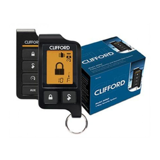
Page 9: Responder Lc Remote Control
Responder LC Remote Control Feature Description Display Status screen - the upper portion of the display contains status icons for the System, Siren, Alarm zones, and Remote Control Text field - the lower portion of display - shows the Clock, Command confirmations, Page messages and Programming menus Command buttons (4) -
Page 10: Control Center
Control Center Control Center Button The Control Center, typically located on the upper part of the front windshield sends and receives commands or messages to and from your system. It consists of: • The In-vehicle system antenna, for 2 way communication. •... -
Page 11: Status Screen Icons
Status Screen Icons Status Screen Icons Text Field The table below describes all the status screen icons. Icon Description Armed: The system is Armed, the alarm is enabled. Locked: The system is Locked in Valet, the alarm is disabled. Disarmed: The system is Disarmed, the alarm is disabled. Unlocked: The system is Unlocked in Valet, the alarm is dis- abled. - Page 12 Icon Description On during a Sensor Zone Full Trigger output On during Fault Report to indicate a Sensor is active and bypassed when arming On during the Door Zone Full Trigger output On during Fault Report to indicate a Door is open and bypassed when arming On during a Hood Zone Full Trigger output On during Fault Report to indicate the Hood is open and...
- Page 13 Icon Description Text field Displays the Clock, message text and feature menus On after the Garage Open** message has been received. On after the Garage Closed** message has been received. Remote start is active, the engine is running (with optional remote start module only).
-
Page 14: Using Your System
Using your System Commands and Confirmations Commands, Basic or Advanced, are used to activate system features and are performed by pressing one of the Command buttons. Basic commands control the most often used features while Advanced com- mands control more specialized features and request reports. Confirmations for Basic or Advanced commands are indicated first by siren chirps and parking light flashes, and then by Text, Icons and beeps or tones on the remote control. -
Page 15: Responder Lc Command Table
Responder LC Command table Direct Access Level Button LEVEL 1 LEVEL 2 LEVEL 3 LEVEL 4 Arm/Lock Silent Arm Sensor Sensor Silent Full Silent (Panic) Bypass Disarm/Unlock Silent Disarm Remote Valet Car Finder Remote Start*/ Aux 1/4** Aux/Trunk AUX 1 AUX 2 AUX 3 AUX 4... -
Page 16: Basic Commands (Direct Access)
Basic Commands (Direct Access) Press and release 6:30 The alarm arms, doors lock (if connected), and the siren chirps and parking lights flash once. The text and beeps play ARMED to confirm and the System Status Icons update. If Valet mode* is On, the doors lock and the text and tone play. -
Page 17: Aux/Trunk
AUX/Trunk Press and hold The Trunk opens (if connected) when this button is pressed for 2 sec- onds. The text and tones play to confirm. TRUNK Remote Start/Aux 1/Aux 4 Press and release Remote Start *** Activates (or if On, deactivates) the remote starter. The engine and parking lights turn on or off accordingly. -
Page 18: Advanced Commands: (Level 1)
Advanced Commands: (Level 1) Press and release the button one time first, before pressing one of the following command buttons. LEVEL 1 Silent Arm Press and release The alarm arms, doors lock (if connected), and the parking lights flash once. The text plays to confirm and the System Status SILENT ARMED icons update. -
Page 19: Advanced Commands: (Level 2)
Advanced Commands: (Level 2) Press and release the button two times first, before pressing one of the following command buttons. LEVEL 2 Sensor Bypass Press and release The parking lights flash each time this command is received to in- dicate the Sensor bypass type. Two flashes indicates sensor Warn- away zones are bypassed. -
Page 20: Advanced Commands: (Level 3)
Advanced Commands: (Level 3) Press and release the button three times first, before pressing one of the following command buttons. Sensor Silent Arm* LEVEL 3 Press and release The alarm arms, doors lock, the siren chirps and parking lights flash three times. -
Page 21: Advanced Commands: (Level 4)
Advanced Commands: (Level 4) Press and release the button four times first, before pressing one of the following command buttons. Full Silent Arm* LEVEL 4 Press and release The alarm arms, doors lock, and the siren chirps and parking lights flash 4 times. -
Page 22: Responder Lc Configuration
Responder LC Configuration Operations of the Responder LC and how it communicates messages are set in the configuration Main Menu. Navigating menus and options Navigating menus and features, changing options, and exiting are performed using the remote control buttons. The following instructions discuss how to access and configure the settings. -
Page 23: Main Menu
Main Menu The following Main Menu list of features is available for configuration of the remote control. Setup Remote menu: Keypad Lock Options: AUTO When , the buttons do not lock and always perform a com- mand when pressed. When set to , the remote buttons AUTO lock after a 20 second lapse between buttons presses to prevent... -
Page 24: Remote Start Info
Off after one week if the remote control is not used during this period. Just press any button to resume system monitoring. When set to it wakes up every few seconds to listen for pages from the system. When set to it does not wake up to receive remote start or alarm trigger pages. -
Page 25: Runtime Alert
Runtime Alert Options: These options are only available when the 2-way remote control is paired to a Directed remote start/keyless entry or remote start/ security system. Car 2 Options: HOME This remote can control two systems independently. When set to , the Car2 select option is not available. -
Page 26: Button Beep
Button Beep Options: When set to , the remote will emit a beep as confirmation of a button press. When set to , beeps are not emitted for button presses. System Type Options: Selects the type of system, namely; Security or Remote Keyless Entry to which the remote has been paired, and adjusts the text and main menu accordingly. -
Page 27: Pair Remote
Pair Remote: Remote Pair is a process where the Responder LC and the system in the vehicle learn each others encrypted identification, securing their communication from intruders. Please note that your remote controls come pre-programmed from the factory. Prepare the vehicle system to be Paired with a new remote Open at least one of the vehicle’s doors. -
Page 28: Demo Mode
Demo mode: Demo Mode plays a pre-selected group of animations as a demon- stration tool to show friends or family. Running Demo mode shortens the battery life over time if used excessively • : The remote will display a selection of icons on SILENT the status screen without beeps and tones then stop •... -
Page 29: Alarm Features
Alarm Features Normal Arm Protection Status LED: The Control Center Status LED flashes as a visual indicator that your vehicle’s security system is active. Starter Kill: The Failsafe starter kill relay prevents the engine from starting Note May require additional parts and installation Sensor triggers: The shock sensor can distinguish minor impacts from major impacts to the vehicle exterior. -
Page 30: Full Silent Arm Protection
Full Silent Arm Protection Sensor Warn-away, Sensor Full Trigger and Point of Entry activations will only send messages to the remote, with parking light flash and siren outputs defeated. Sensor Warn-away Messages When the remote receives a Sensor Warn-away message it emits 10 beeps (if on) and displays a sensor zone specific SENSOR WARN text for 30 seconds. -
Page 31: Trigger Zone Fault Report
Trigger Zone Fault Report When armed by remote command the system runs a status check of the alarm trigger zones. Faulty zones (usually caused by dome light delay or open trunk) are bypassed and reported via the control center LED and remote, while all other trigger zones remain active and are monitored to protect the vehicle. -
Page 32: Alarm Report When Requested
Table of Zones Zone # (led flashes) Zone Name Trunk Shock Sensor Door Sensor 2 Ignition Hood Alarm Report when requested The Alarm Report displays the two most recent alarm triggers depend- ing on the system state when requested. When disarmed, the report will display text to identify the two most recent triggers since the ve- hicle was last driven. -
Page 33: Remote And System Operations
Remote and System Operations Passive Arming* Park and exit the vehicle, after the doors are closed the Passive arm- ing countdown begins. The led flashes quickly and upon reaching 20 seconds the siren then chirps once. At 30 seconds the system arms itself. -
Page 34: Valet Mode
Valet Mode Valet mode can be entered and exited by performing the Remote Valet command or manually using the vehicle key and the control button. When entered, the alarm functions are defeated while the conve- nience features still operate normally. Arm and Disarm commands lock and unlock the doors while the text and beeps play to confirm. -
Page 35: Out Of Range
Out of Range Each time a command is performed the remote will expect a com- mand confirmation from the system. If a command confirmation is not received the out-of-range icon ( ) and a fault tone will play as an alert. - Page 36 the ignition is turned on. The siren chirps and parking lights flash once to confirm arming. The text and beeps play, and the system ARMED status icons update to confirm arming. If valet mode is on, the text and tone plays, exit valet NOT AVAILABLE mode before arming VRS.
-
Page 37: 1-Way Companion Remote Control
1-way Companion Remote Control Direct Access Level Button LEVEL 1 LEVEL 2 LEVEL 3 LEVEL 4 Arm/Lock Silent Arm Sensor Sensor Silent Full Silent (Panic) Bypass Disarm/ Silent Disarm Remote Valet Car Finder Unlock Remote Start Runtime Timer Start Smart Start Defogger Reset Aux/Trunk... -
Page 38: 1-Way Remote Control Configuration
1-way Remote Control Configuration The remote controls have operations that can be configured to a user’s personal preferences. The following instruction will direct you through the available configuration and programming options for the remote control. Remote Features To Enter Programming: Press and hold the button for eight seconds until the transmit LED turns on, then release the... -
Page 39: Feature Descriptions
Note: The remote control will automatically exit the configuration mode if no buttons are pressed for 30 seconds, letting the remote exit programming on its own will not save any of the feature changes. Feature Descriptions Keypad Lock Options: Off, Auto When Off, the buttons do not lock and will always perform a com- mand when pressed. -
Page 40: Remote Pairing
Triggers Only, beeps will only be emitted for Full Trigger Messages on the 2-way remote (if applicable). Car 2 Options: Off, On The Responder LE and 1-way companion remote controls can control two systems independently. When set to Off, the Car Select feature is not available. - Page 41 LED will begin flashing and the horn (if connected) will sound one time to confirm the system is ready for pairing. Release the control button. Press the button on the remote. The horn (if connected) will sound to confirm pairing. To exit the pairing mode on the remote, press the button twice, the transmit LED will shut off to confirm exiting.
-
Page 42: System Expansion Options
System Expansion Options Controlling two vehicles (Car Select) The Responder LC and 1way companion remote can control systems in two different vehicles saving the need for multiple remote controls. This feature also allows for customized system configurations on each vehicle that has more than one driver. See Owner Recognition follow- ing for details. - Page 43 Driver door priority unlocking The door unlocking operation can be configured to emulate an OEM style of driver priority unlocking for added security during disarming. Auxiliary Channels The Auxiliary Channel outputs of this system can activate many of the convenience features found in today’s vehicles. Once a command is performed to activate a convenience feature the Responder LC dis- plays text that matches the feature.
-
Page 44: Battery Information (Responder Lc)
Battery Information (Responder LC) The Responder LC remote control is powered by an internal recharge- able battery that can be serviced only through an authorized Directed dealer. The information and precautions in this section can help maxi- mize your battery’s life and usage in providing your Responder LC remote control with many years of trouble free operation. -
Page 45: Battery Life
siren will emit one additional chirp as an alert. If confirmation chirps are programmed off, the system will still emit one chirp as an alert when disarming. After performing a command, and several LOWBAT beeps play on the Responder LC remote to indicate the battery needs to be charged. -
Page 46: Battery Information (1-Way)
Battery Information (1-Way) The 1-way companion remote is powered by one 3V coin cell lithium battery (PN CR-2032) that can be purchased at most retailers. When the battery begins to weaken, the operating range is reduced. Battery Replacement If present, remove the small screw on the back of the remote. Use a small flat blade screwdriver and insert it into the slot locat- ed along the bottom of the remote, near the key ring. -
Page 47: Glossary Of Terms
Glossary of Terms Document Terminology Control Module The “brain” of your system. Usually hidden underneath the dash area of the vehicle. It houses the microprocessor which monitors your vehicle and controls all of the system’s func- tions. Responder LC (2-way A hand-held, remote control which operates the various func- Remote Control) tions of your system and receives messages and pages from... -
Page 48: Patent Information
Patent Information This product is covered by one or more of the following United States patents: Remote Start Patents: 5,349,931; 5,872,519; 5,914,667; 5,952,933; 5,945,936; 5,990,786; 6,028,372; 6,467,448; 6,561,151; 7,191,053; 7,483,783 Vehicle Security Patents: 5,467,070; 5,532,670; 5,534,845; 5,563,576; 5,646,591; 5,650,774; 5,673,017; 5,712,638; 5,872,519; 5,914,667; 5,952,933;... -
Page 49: Government Regulations
Government Regulations This device complies with Part 15 of FCC rules. Operation is subject to the fol- lowing two conditions: (1) This device may not cause harmful interference, and (2) This device must accept any interference received, including interference that may cause undesirable operation. This equipment has been tested and found to comply with the limits for a class B digital device, pursuant to Part 15 of the FCC Rules. - Page 50 Control Center To satisfy FCC RF exposure compliance requirements, the device and its an- tenna must maintain a separation distance of 20 cm or more from the person’s body, except for the hand and wrists, to satisfy RF exposure compliance. This device complies with the Industry Canada Radio Standards Specification RSS 210.
-
Page 51: Additional Information
Additional Information Please read the safety warnings below before proceeding. Improper use of the product may be dangerous or illegal. Installation Due to the complexity of this system, installation of this product must only be performed by an authorized Directed dealer. If you have any questions, ask your retailer or contact Directed directly at 1-800-753-0600. -
Page 52: Limited Lifetime Consumer Warranty
Limited lifetime consumer warranty Directed Electronics. (“Directed”) promises to the original purchaser to repair or replace (at Directed’s election) with a comparable reconditioned model any Directed unit (hereaf- ter the “unit”), excluding without limitation the siren, the remote transmitters, the associated sensors and accessories, which proves to be defective in workmanship or material under reasonable use during the lifetime of the vehicle provided the following conditions are met: the unit was purchased from an authorized Directed dealer, the unit was professionally... - Page 53 ANY CONSEQUENTIAL DAMAGES OF ANY KIND. IN THE EVENT OF A CLAIM OR A DISPUTE INVOLVING DIRECTED OR ITS SUBSIDIARY, THE VENUE SHALL BE SAN DIEGO COUNTY IN THE STATE OF CALIFORNIA. CALIFORNIA STATE LAWS AND APPLICABLE FEDERAL LAWS SHALL APPLY AND GOVERN THE DISPUTE. THE MAXIMUM RECOVERY UNDER ANY CLAIM AGAINST DIRECTED SHALL BE STRICTLY LIMITED TO THE AUTHORIZED DIRECTED DEALER’S PURCHASE PRICE OF THE UNIT.
Need help?
Do you have a question about the 3706X and is the answer not in the manual?
Questions and answers