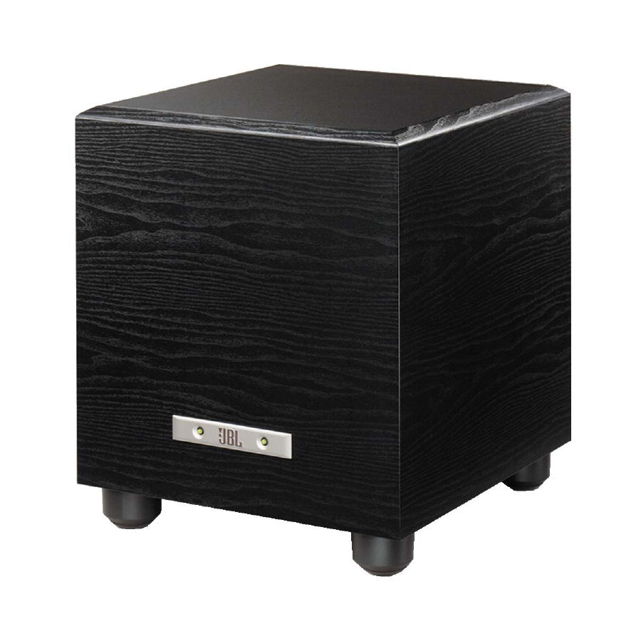
JBL PowerBass PB10 Service Manual
Powerbass series
Hide thumbs
Also See for PowerBass PB10:
- Owner's manual (9 pages) ,
- Service manual (54 pages) ,
- Preliminary service manual (20 pages)
Summary of Contents for JBL PowerBass PB10
- Page 1 PowerBass Series PB10 Subwoofer SERVICE MANUAL JBL Incorporated 250 Crossways Park Dr. REV 0 7/00 Woodbury, New York 11797...
-
Page 2: Table Of Contents
PB10 TABLE OF CONTENTS Safety Information ..........3 Basic Specifications . -
Page 3: Safety Information
PB10 SAFETY INFORMATION... -
Page 4: Basic Specifications
PB10 BASIC SPECIFICATIONS PB10 Subwoofer... -
Page 5: Detailed Specifications
PB10 DETAILED SPECIFICATIONS PB10 Subwoofer... -
Page 6: Controls And Their Function
Front Panel Power - These lights will be red when the unit is plugged in and not receiving a signal; when the PB10 receives a signal, the lights will cycle to GREEN. If no signal is received after 10-15 minutes the lights will cycle back to RED (standby) until a signal is present again. -
Page 7: Speaker Connection
PB10 Speaker Connection examples to determine which the hole through the When we designed the PB10 and PB12 powered description best matches your centerpost is visible under the system and follow the collar. subwoofers, our goal was to offer the user the best possible... -
Page 8: Dolby Pro Logic Line Level
PB10 Dolby Pro Logic (Non-Digital)-Line Level Use this installation method for position with Dolby Pro Logic- Make sure your receiver or Dolby Pro Logic applications only processors. processor is configured (not Dolby Digital, DTS or correctly; Make sure that the... -
Page 9: Dolby Digital Or Dts Connection
PB10 Dolby Digital or DTS (or Other Digital Surround Mode) Connection Use this installation method for you may connect the The front left, front right, center Dolby Digital, DTS or other subwoofer output on your and rear speakers should be... -
Page 10: Operation
Note: It will take several when the subwoofer is not minutes for the LEDs to turn receiving a signal. The PB10 Level Control room size, subwoofer The subwoofer Level Control placement, type of main adjusts the volume of the speakers and listener position. -
Page 11: Troubleshooting
PB10 Phase Control The Phase Control determines bass output at the listening If at some time in the future whether the subwoofer’s position. you happen to rearrange your piston-like action moves in and listening room and move your Remember, every system,... -
Page 12: Test Setup And Procedure
PB10 PB10 TEST SET UP AND PROCEDURE AC VOLT METER (6V) LEVEL FROM LINE LEVEL LINE-LEVEL CD PLAYER NORMAL SOURCE PHASE CROSSOVER FREQUENCY 50 Hz 150 Hz PRE AMP PB10 or PB12 LINE LEVEL IN UNDER TEST USE L or R... -
Page 13: Exploded And Packaging
PB10 Exploded and Packaging Views MECHANICAL & PACKING PARTS LIST 10” Woofer 203400 Foot 203410 Outer Carton 203420 Owner’s Manual 120V 203430 Amplifier Complete 203450 Foot Screw 203411 Foam corners (package drawing): Top Corner 4/carton 203460 Bottom Corner 4/carton 203470... -
Page 14: Amplifier Exploded View
PB10 Amplifier Exploded View LEGEND Dual RCA jack 108324 Power Transformer 80135 Level Pot 40402 Low Pass Filter Pot 40707 Fuse Clips (2) 70323 1.25A SLO-BLO Fuse (3ag) 80114... -
Page 15: Amplifier Faceplate
PB10 Amplifier Faceplate Parts LEVEL KNOB 70313 LFE DEFEAT SWITCH PHASE 70150 SWITCH 70150 LEVEL CROSSOVER PB10 FACEPLATE FREQUENCY KNOB NORMAL 70325 70313 PHASE CROSSOVER FREQUENCY 50 Hz 150 Hz HI LEVEL I/O LINE LEVEL IN 108116 USE L or R... -
Page 16: Integrated Circuit Diagrams
PB10 Integrated Circuit Diagrams S53AMI/S64AMI - Power Amp module SAFETY PART NOTE: THE FOLLOWING PROCEDURES MUST BE FOLLOWED WHEN INSTALLING NEW S53AMI/S64AMI AMP MODULES: +6V 15 FAILURE TO FOLLOW ONE OR MORE OF THESE STEPS MAY RESULT IN THE INSTANT DESTRUCTION OF THE MODULE WHEN POWERED UP. -
Page 17: Testing Procedure
PB10 PB10 Testing Procedure... - Page 18 PB10 PB10 Testing Procedure (Cont.)
- Page 19 PB10 PB10 Testing Procedure (Cont.)
-
Page 20: Electrical Parts List
PB10 PB10 Electrical Parts List PB10 POWER AMP section of PCB Version 6.3. Part # Designator Description... - Page 21 PB10 PB10 Electrical Parts List (Cont.) PB10 POWER AMP section of PCB Version 6.3. Part # Designator Description...
- Page 22 PB10 PB10 Electrical Parts List (Cont.) PB10 POWER AMP section of PCB Version 6.3. Part # Designator Description...
- Page 23 PB10 PB10 Electrical Parts List (Cont.) PB10 PREAMP section of PCB Version 6.3. Part # Designator Description...
-
Page 24: Printed Circuit Boards
PB10 PB10 PCB’s... - Page 25 PB10 PCB’s (Cont.)
- Page 26 PB10 PCB’s (Cont.)
-
Page 27: Schematics
PB10 Schematics... - Page 28 PB10 Schematics (Cont.)


Need help?
Do you have a question about the PowerBass PB10 and is the answer not in the manual?
Questions and answers