
Subscribe to Our Youtube Channel
Related Manuals for JBL PSW-D110


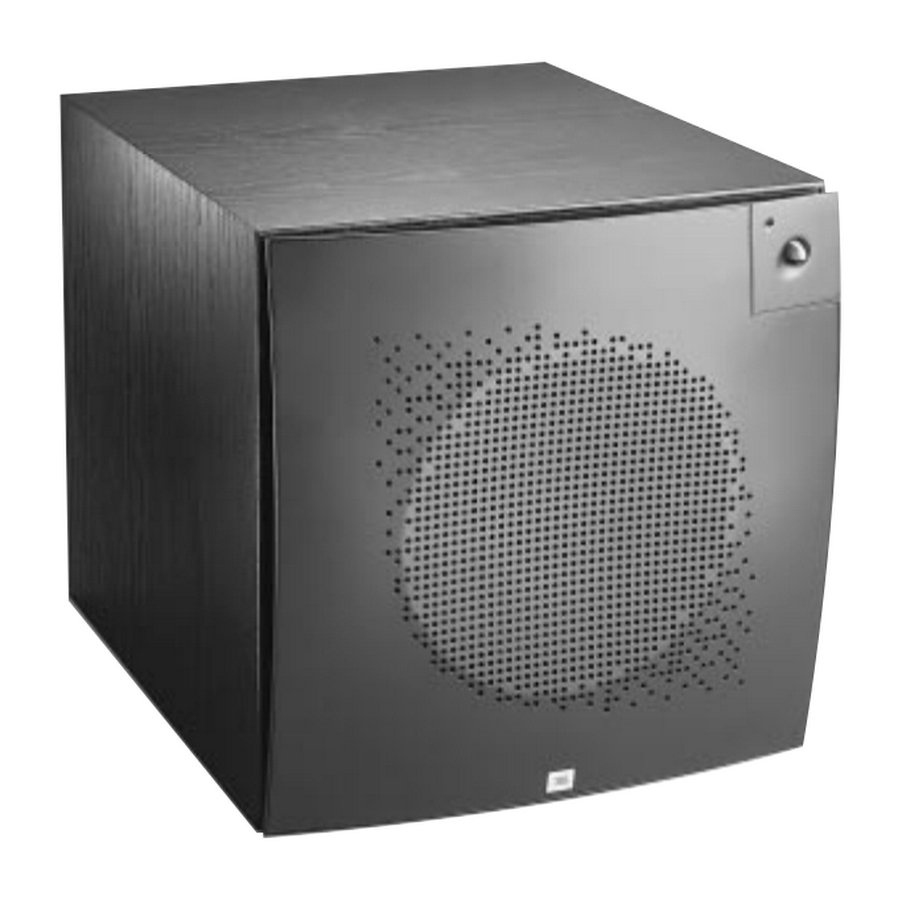
Summary of Contents for JBL PSW-D110
- Page 1 PSW-D110/DPS-10 Powered Subwoofer SERVICE MANUAL JBL Consumer Products Inc. 250 Crossways Park Drive Woodbury, N.Y. 11797 1-800-336-4JBL in the USA A Harman International Company Rev G 6/2001...
-
Page 2: Safety Information
Use only factory replacement Main PCB IMPORTANT SERVICE NOTES: When testing the PSW-D110/DPS-10 Series amplifier, a load must always be connected to the output terminals, whether the woofer, or a 4 to 8 ohm resistive load. All AC powered test instruments (meters, oscilloscopes, etc.) must have a floating ground, i.e., be... -
Page 3: Table Of Contents
PSW-D110/DPS-10 Version 3.93 PCB AND PROCEDURE............10 (Solder Side) ..............24 PSW-D110/DPS-10 POWER AMP PSW-D110/DPS-10 ELECTRICAL PARTS LIST ..25 TEST PROCEDURE and FLOW CHART ....11 PSW-D110/DPS-10 INTEGRATED CIRCUITS ...26 SERVICE BULLETIN JBL9902 REV1 - MAY 1999 ..14 PWS-D110/DPS-10 SCHEMATIC 1 of 2.....27 SERVICE BULLETIN JBL9903 - APRIL 1999 ....15... -
Page 4: Detailed Specifications
Amplifier/Subwoofer PSW-D110/DPS-10 DETAILED SPECIFICATIONS LINE VOLTAGE Yes/No Hi/Lo Line Unit Notes US 120vac/60Hz 108-132 Vrms Normal Operation EU 230vac/50-60Hz 207-264 Vrms Normal operation, MOMS required Parameter Specification Unit Conditions Notes Amp Section Type (Class AB, D, other) Class D Preferred...Sink required for Class AB... - Page 5 Amplifier/Subwoofer PSW-D110/DPS-10 Limiter (yes/no) T H D a t M a x . O u t p u t Maximum Output Power Maximum THD as a result of limiting. Power Features Phase Switch (yes/no) — V o l u m e...
-
Page 6: Psw-D110/Dps-10 Controls And Their Function
Front Panel ( PSW-D110 only) 1. Power - (PSW-D110 ONLY) This light will be RED when the unit is plugged in and not receiving a signal; when the PSW-D110 receives a signal, the light will cycle to GREEN. If no signal is received after 10 – 15 minutes the light will cycle back to RED (standby) until a signal is present again. -
Page 7: Operation
Amplifier/Subwoofer PSW-D110/DPS-10 OPERATION Crossover Adjustments Phase High-Pass Control Phase Control • This control is only active if you are using the hook-up The Phase Control determines whether the subwoofer method described in detail on page 8, Figure 3. The speaker’s piston-like action moves in and out with the main High-Pass control determines the frequency at which the speakers, 0°... -
Page 8: Speaker Connections
Amplifier/Subwoofer PSW-D110/DPS-10 SPEAKER CONNECTIONS NOTE: The rear plate for the PSW-D110 is shown, which has the level control on the front panel. The DPS-10 has this level control on the rear panel (amplifier) Figure 1 2) If your receiver/amplifier has subwoofer outputs or preamp output jacks for the left and right channels. -
Page 9: Troubleshooting
Amplifier/Subwoofer PSW-D110/DPS-10 TROUBLESHOOTING If you used the high-level (speaker) inputs and there is no • Powered subwoofer is plugged in. sound from any of the speakers, check the following: • Adjust the crossover point. • Receiver/amplifier is on and a source is playing. -
Page 10: Psw-D110/Dps-10 Test Set Up And Procedure
NOTE: When testing the PSW-D110/DPS-10 amplifier, a load must always be connected to the output terminals, whether the woofer, or a 4 to 8 ohm resistive load. -
Page 11: Psw-D110/Dps-10 Power Amp Test Procedure And Flow Chart
PSW-D110/DPS-10 TEST PROCEDURE A. Power Amp Section 1. Resistance Check Resistance from O/P of the module to GND should be >10K (NO LOAD) Resistance from V+ of the module to V- of the module should read >5k Resistance from V+ of the module to O/P of the module should read >10K Resistance from V- of the module to O/P of the module should read >10K... - Page 12 4. High-Pass -Set up Set Generator at 100mV@at 100Hz Signal to Low level input Measure voltage at high-pass output -Voltage measurement Hi-Pass Pot Setting Output 24mV 55mV 4. LED With a 35mV input signal at a single Low level input, LED should change to green See flow chart (following page) for detailed diagnostics.
- Page 13 PSW-D/DPS-10 POWER MODULE TESTING FLOW CHART CAUTION : MODULE OUTPUT IS FLOATING AND IS NOT PROTECTED AGAINST A SHORT TO GROUND. ALL TEST INSTRUMENTS CONNECTED TO THE OUTPUT MUST BE FLOATING. ATTACH THE SCOPE PROBE TIP TO SPK - and REFERENCE LEAD TO SPK+.
-
Page 14: Service Bulletin Jbl9902 Rev1 - May 1999
Model: PSW-D110 Subject: Grille removal When servicing the PSW-D110 subwoofer, care must be taken when removing the metal subwoofer speaker grille. Removing the grille by grasping one grille edge and pulling it off with a hinge-like action could result in broken grille pins. -
Page 15: Service Bulletin Jbl9903 - April 1999
When troubleshooting, failure to check these joints can result in erroneous conclusions or wasted time. In the event you receive a PSW-D110, PSW-D112, ARC SUB 8 or ARC SUB 10 Subwoofer with the complaints “Dead, or No Output, or Motorboating (Oscillation)”, perform the steps listed below first before any further troubleshooting takes place: 1) Unplug all cables, lay the subwoofer on a padded surface. -
Page 16: Service Bulletin Jbl2000-01 - January 2000
Models: PSW-D110, DPS-10, ARC SUB8, ARC SUB10, DS-10 Subject: Failure of C6 In the event you receive a JBL subwoofer corresponding to one of the above models with the complaint “no output” and capacitor C6 (10uf 50v NPE) is damaged in the amplifier: Order kit JBL part# 30721 and replace the following included parts: C6 –... -
Page 17: Cabinet Exploded Views
Amplifier/Subwoofer PSW-D110/DPS-10 CABINET EXPLODED VIEWS... -
Page 18: Amplifier Exploded View
Amplifier/Subwoofer PSW-D110/DPS-10 AMPLIFIER EXPLODED VEIW... -
Page 19: Psw-D110/Dps-10 Mechanical Parts List
For grille replacement, there are two versions of the grille. Earlier version has a .220" (5.6mm) grille pin diameter. JBL Part# 200510. Later version has a .410" (10.4mm) grille pin diameter. JBL Part# 200511. In the case of a missing grille, where pin... -
Page 20: Packing Exploded Views
Amplifier/Subwoofer PSW-D110/DPS-10 PACKING EXPLODED VIEWS... -
Page 21: Psw-D110/Dps-10 Version 3.53 Pcb (Component Side)
Amplifier/Subwoofer PSW-D110/DPS-10 PSW-D110/DPS-10 Version 3.53 PCB (Component Side) -
Page 22: Psw-D110/Dps-10 Version 3.53 Pcb (Solder Side)
Amplifier/Subwoofer PSW-D110/DPS-10 PSW-D110/DPS-10 Version 3.53 PCB (Solder Side) -
Page 23: Psw-D110/Dps-10 Version 3.93 Pcb (Component Side)
Amplifier/Subwoofer PSW-D110/DPS-10 PSW-D110/DPS-10 Version 3.93 PCB (Component Side) -
Page 24: Psw-D110/Dps-10 Version 3.93 Pcb (Solder Side)
Amplifier/Subwoofer PSW-D110/DPS-10 PSW-D110/DPS-10 Version 3.93 PCB (Solder Side) -
Page 25: Psw-D110/Dps-10 Electrical Parts List
Amplifier/Subwoofer PSW-D110/DPS-10 PSW-D110/DPS10 PARTS LIST Ref.# PartNumber Description Ref.# PartNumber Description Low Pass 40425 0.25W 10% DOUBLE LOG POT 30705 10uF 50V -4% ELECTROLYTIC RADIAL NP 1 SAFETY PART SeePage16ServiceBulletin Level 40402 0.25W 10% SINGLE LINEAR POT 30510 33nF 50V 10% MONO-CERAMIC AXAIL... -
Page 26: Psw-D110/Dps-10 Integrated Circuits
Amplifier/Subwoofer PSW-D110/DPS-10 PSW-D110/DPS-10 INTEGRATED CIRCUITS S53AMI/S64AMI - Power Amp module SAFETY PART NOTE: THE FOLLOWING PROCEDURES MUST BE FOLLOWED WHEN INSTALLING NEW S53AMI/S64AMI AMP MODULES: FAILURE TO FOLLOW ONE OR MORE OF THESE STEPS MAY RESULT IN THE INSTANT DESTRUCTION OF THE MODULE WHEN POWERED UP. -
Page 27: Pws-D110/Dps-10 Schematic 1 Of 2
Amplifier/Subwoofer PSW-D110/DPS-10 PWS-D110/DPS-10 SCHEMATIC 1 of 2... -
Page 28: Pws-D110/Dps-10 Schematic 2 Of 2
Amplifier/Subwoofer PSW-D110/DPS-10 PWS-D110/DPS-10 SCHEMATIC 2 of 2...
Need help?
Do you have a question about the PSW-D110 and is the answer not in the manual?
Questions and answers