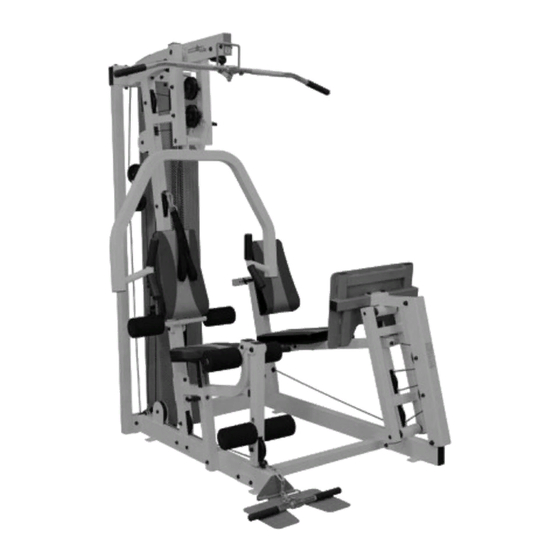
Summary of Contents for Ironman Fitness 600g
- Page 1 A A L L O O W W N N E E R R ’ ’ S S Questions? Call our toll free Ironman Fitness Helpline 1 - 8 0 0 - 7 5 0 - 4 7 6 6...
- Page 2 THANK YOU for making the IRONMAN 600g unit a part of your exercise program. IRONMAN assures the very best in value, appearance, durability and biomechanics. This manual will guide you through the assembly process. If at any time you are having trouble with the assembly or use of this product, then please con- tact us at our Ironman Fitness Helpline.
-
Page 3: Before You Start
• This unit should only be used on a level surface and is intended for indoor use only. Ironman Fitness recommends an equipment mat be placed under the unit to protect the floor or carpet and for easier cleaning. - Page 4 PARTS...
- Page 5 PARTS...
- Page 6 PARTS...
- Page 7 PARTS...
-
Page 8: Parts List
DESCRIPTION Base Frame Foot Plate Main Upright Rear Cross Beam Rear Top Beam Main Top Beam Foot Plate Bracket Lat Pull Down Bar Seat Pad Support Receptacle Leg Extension Lever Back Pad Support Press Arm Support Press Arm Rear Upright Front Cross Link Beam L-Pin (Long) Seat Pad Support... - Page 9 NOTE: Hand tighten bolts and nylon nuts until machine is fully assembled. Do not use bolt here yet. Wait for STEP 6. Do not use bolt here yet. Wait for STEP 6.
- Page 10 ASSEMBLY NOTE: Hand tighten bolts and nylon nuts until machine is fully assembled.
- Page 11 ASSEMBLY NOTE: Hand tighten bolts and nylon nuts until machine is fully assembled.
- Page 12 ASSEMBLY NOTE: Hand tighten bolts and nylon nuts until machine is fully assembled. Feed Cable (63) through framework as pictured. Hold cable in place by placing in pulley grooves and bolting pulleys to frame.
- Page 13 NOTE: Hand tighten bolts and nylon nuts until machine is fully assembled. Note: Make sure the selector pin hole on all weight plates are facing toward the unit. First, insert guide rods into rear cross beam (4). Then slide on, from top to bot- tom, rubber bushings (125), 19 weight plates (128) and weight plate assembly (50).
- Page 14 ASSEMBLY NOTE: Hand tighten bolts and nylon nuts until machine is fully assembled.
- Page 15 ASSEMBLY NOTE: Hand tighten bolts and nylon nuts until machine is fully assembled.
- Page 16 ASSEMBLY NOTE: Hand tighten bolts and nylon nuts until machine is fully assembled.
- Page 17 ASSEMBLY NOTE: Hand tighten bolts and nylon nuts until machine is fully assembled. Hex Screws (109) are already pre-assembled for you. Make sure to unscrew them before sliding in shafts (43).
- Page 18 ASSEMBLY NOTE: Hand tighten bolts and nylon nuts until machine is fully assembled. Note: Hex screws (109) are already pre-assembled for you. Make sure to unscrew them before sliding in shaft(39).
- Page 19 ASSEMBLY NOTE: Hand tighten bolts and nylon nuts until machine is fully assembled. Note: Hex screws are already pre-assembled for you. Make sure to unscrew them before sliding in shaft (39).
- Page 20 ASSEMBLY NOTE: Hand tighten bolts and nylon nuts until machine is fully assembled.
- Page 21 ASSEMBLY NOTE: Hand tighten bolts and nylon nuts until machine is fully assembled.
- Page 22 ASSEMBLY NOTE: Hand tighten bolts and nylon nuts until machine is fully assembled.
- Page 23 ASSEMBLY NOTE: Hand tighten bolts and nylon nuts until machine is fully assembled.
- Page 24 ASSEMBLY NOTE: Hand tighten bolts and nylon nuts until machine is fully assembled.
- Page 25 ASSEMBLY NOTE: Hand tighten bolts and nylon nuts until machine is fully assembled. STEP 24 Feed cable (62) through framework as pictured. Hold cable in place by setting in pulley grooves and bolting pulleys to frame or as pictured. View finished assembly of this step in future steps or on cover page for guidance.
- Page 26 ASSEMBLY NOTE: Hand tighten bolts and nylon nuts until machine is fully assembled. Feed remaining section of cable (63) through leg press framework. Hold cable in place by setting in pulley grooves and bolting pulleys to frame.
- Page 27 ASSEMBLY NOTE: Hand tighten bolts and nylon nuts until machine is fully assembled. Feed cable (64) through framework. Hold cable in place by setting in pulley grooves and bolting pulleys to frame.
- Page 28 ASSEMBLY NOTE: Hand tighten bolts and nylon nuts until machine is fully assembled.
- Page 29 ASSEMBLY NOTE: Hand tighten bolts and nylon nuts until machine is fully assembled. Before securing weight stack covers (25,26): 1. Make sure to lightly lube the guide rods with the supplied lubrication. 2. Place the weight stack plate numbers on the weight plates.
- Page 30 EXPLODED VIEW...
- Page 31 This warranty DOES NOT COVER shipping charges, export taxes, custom duties and taxes, or any other charges associated with transportation of the parts or Product. To obtain warranty service, you must contact an Ironman authorized retailer, service technician or Ironman Fitness at our phone number located in this manual. Any parts deter- mined to be defective must be returned to Ironman to obtain warranty service.
- Page 32 Customer Service (800) 750-4766 Ironman Fitness Products 4009 Distribution Drive Suite 250 Garland, TX 75041 www.ironmanfitness.com Ironman and M-dot are registered trademarks of the World Triathlon Corp., used here by permission.


Need help?
Do you have a question about the 600g and is the answer not in the manual?
Questions and answers