Table of Contents

Related Manuals for Quickie Pulse


Summary of Contents for Quickie Pulse
- Page 1 P u l s e Quickie ® Pulse 6 BC, 6 SC O w n e r ’ s M a n u a l SUPPLIER: This manual must be given to the rider of this wheelchair. RIDER: Before using this wheelchair read this entire manual and save for future reference.
-
Page 2: Introduction
Q U I C K I E P U L S E I . I N T RO D U C T I O N USER WARNING I. INTRODUCTION WARNING SUNRISE LISTENS Attention wheelchair users, do not operate this wheel- chair without first reading the owner’s manual. -
Page 3: Table Of Contents
Q U I C K I E P U L S E I I . TA B L E O F C O N T E N T S J. Upholstery Fabric ............II. TABLE OF CONTENTS K. Suspension..............I. INTRODUCTION ........... L. -
Page 4: Your Chair And Its Parts
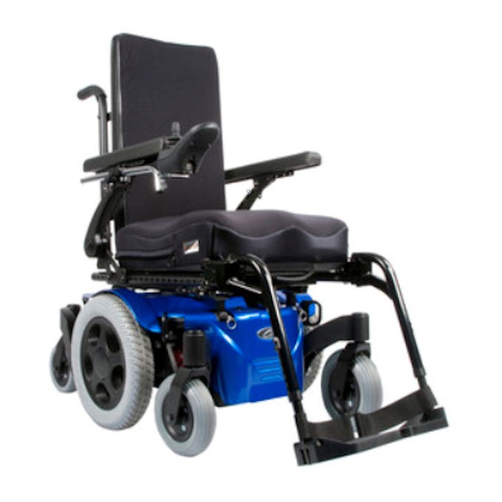
ELR center mount (optional) 7. Drive wheels 8. Freewheel release 9. Caster Fork (front) 10. Caster Fork (rear) 11. Shroud Models Pulse 6 BC Pulse 6 SC (shown) QUICKIE PULSE Weight Casters (front) Standard- 7” solid Colors complete chair: 260 lbs 235 lbs... -
Page 5: Notice- Read Before Use
Q U I C K I E P U L S E I V. N OT I C E – R E A D B E F O R E U S E C. REVIEW THIS MANUAL OFTEN IV. NOTICE– READ BEFORE USE Before using this chair you, and each person who may assist you, should read this entire Manual and make sure to follow all instruc- A. -
Page 6: D.distance From The Source
20 V/m immunity level will protect the power wheelchair user from the more common sources of radio waves. 3. The Quickie Pulse with the following configuration was test- ed and found to be immune to at least 20 V/m: Quickie Pulse power wheelchair with a right-hand mounted RNET controller, A.S.A.P . -
Page 7: General Warnings
Q U I C K I E P U L S E V I . G E N E R A L WA R N I N G S D. CONTROLLER SETTINGS VI. GENERAL WARNINGS WARNING WARNING Be aware that you may need to adjust the controller Heed all warnings in this section. -
Page 8: H.when Seated In A Parked Wheelchair
Q U I C K I E P U L S E V I . H. WHEN SEATED IN A PARKED K. STREET USE WHEELCHAIR WARNING In most states, power chairs are not legal for use on WARNING public roads. Be alert to the danger of motor vehicles 1. -
Page 9: O.reaching Or Leaning
Q U I C K I E P U L S E V I . 2. Make sure motor locks are engaged. This keeps the chair P . DRESSING OR CHANGING CLOTHES from moving when you transfer. WARNING 3. Work with your health care professional to learn safe methods. Be aware that your weight will shift if you dress or •... -
Page 10: To Reduce The Risk Of Falls, Tip-Over Or Loss Of Control
Q U I C K I E P U L S E V I . T. TO REDUCE THE RISK OF A FALL, V. WHEELCHAIR LIFTS TIP-OVER OR LOSS OF CONTROL WARNING Wheelchair lifts are used in vans, buses, and buildings to WARNING help you move from one level to another. -
Page 11: Warnings: Components & Options
Q U I C K I E P U L S E V I I . WA R N I N G S : C O M P O N E N T S & O P T I O N S •... -
Page 12: Upholstery Fabric
Q U I C K I E P U L S E V I I . J. UPHOLSTERY FABRIC 2. Drive Inhibit This power chair is designed to automatically reduce driving WARNING speed when the power seating is tilted more than 16°. 1. -
Page 13: Set-Up, Adjustment & Use
Q U I C K I E P U L S E VIII. SET-UP, ADJUSTMENT & USE NOTES: 1. Work Surface For Set-Up: Use a flat surface, such as a table, to assemble, adjust and check your chair. This makes the steps easier and helps ensure a correct set-up. -
Page 14: Battery Removal
Q U I C K I E P U L S E V I I I . A. BATTERY REMOVAL (Figures 1, 2, 3) To remove the batteries for transporting or servicing: 1. Remove Batteries a. Carefully remove seat (see Section I. Seat Removal). b. -
Page 15: C.swing-Away Footrests
Q U I C K I E P U L S E V I I I . C. SWING-AWAY FOOTRESTS 1. Installation (Fig. 7) a. Place swing-away pivot pin (E) into the locating hole (F) on top of the hanger mount with the footrest facing outward from frame. -
Page 16: Joystick
Q U I C K I E P U L S E V I I I . E. JOYSTICK joystick power module Controls: • LED Joystick and color display joystick Omni Input/Display The Omni is a universal specialty controls interface that accepts signals from many different types of SIDs and translates them into commands compatible with the PG Drives Technology communication RNET control system. -
Page 17: H.seat Height Adjustment
Q U I C K I E P U L S E V I I I . H. SEAT HEIGHT ADJUSTMENT (Figure 11) 1. Remove seat (See Section I. Seat Removal). 2. Remove pins from all four seat mount posts. 3. -
Page 18: Operating Guide
The On-board Programmer or RNET PC Programmer lets you adjust the control settings of the Pulse. Listed below are a few of the many settings that can be adjust via the On-board Programmer or RNET PC Programmer. (See RNET OBP Owners Manual for full program- mable parameters.) -
Page 19: Vr2 Joystick Assembly
Q U I C K I E P U L S E I X . E. VR2 JOYSTICK ASSEMBLY The standard VR2 joystick controls the chair’s performance. It consists of the following parts: 1. Speed Control or Drive Mode Selection Buttons (A and B) To decrease the speed level depress button A. -
Page 20: Led Joystick
Q U I C K I E P U L S E I X . F. LED JOYSTICK On/Off Button The on/off button applies power to the control system electronics, which in turn supply power to the wheelchair’s motors. Do not use the on/off button to stop the wheelchair unless there is an emergency. -
Page 21: G.color Lcd Screen
Q U I C K I E P U L S E I X . G. COLOR LCD SCREEN This section covers those joystick modules that are fitted with a color LCD screen. The color LCD screen is split into three areas of information. The Top Bar, the Base Bar and the Main Screen Area. -
Page 22: H.motor Locks
Q U I C K I E P U L S E I X . H. MOTOR LOCKS Disconnect the motor locks when you need to manually push the chair. (For example, in an emergency, or if batteries fail). WARNING 1. -
Page 23: Batteries
Q U I C K I E P U L S E X . B AT T E R I E S • Never charge a frozen battery. A fully charged battery will X. BATTERIES rarely freeze, but the fluid in a discharged battery can freeze at 16 degrees Fahrenheit (minus 9 degrees Centigrade). -
Page 24: Charging Batteries
Q U I C K I E P U L S E ALWAYS: WARNING 1. Use the charger that comes with your wheelchair. Read and Batteries weigh up to 45 pounds. Lifting batteries may follow all instructions and warnings. 2. Make sure room is well ventilated. cause back strain. -
Page 25: Maintenance
Q U I C K I E P U L S E X I . M A I N T E NA N C E 2. Adding Water: (Wet Cells Only) XI. MAINTENANCE • Wet-type lead acid batteries need periodic replacement of water lost. -
Page 26: H.maintenance Chart
Service by authorized supplier I. WIRING DIAGRAMS CG TILT (SB ONLY) CHARGER DUAL TOGGLE DRIVE THRU VR2 Joystick Wiring Diagram NOTE– Pulse 5 brake is 24V Pulse 6 brake is 12V BRAKE BRAKE SOLENOID SOLENOID LEFT RIGHT MOTOR MOTOR 70A FUSE... - Page 27 Q U I C K I E P U L S E X I . 4-Way Attendant Tyco Bus Hand Control Offboard VR2 BUS 4-Way Hand Control Charger SPLITTER Tyco Bus 4-Way 2-Way PGD Tyco Bus Actuator VR2 Drive-Thru Single Actuator Inhibit2 Power Module (with battery detail)
-
Page 28: Sunrise Limited Warranty
Q U I C K I E P U L S E X I I . S U N R I S E L I M I T E D WA R R A N T Y E. WHAT WE WILL DO XII.
Need help?
Do you have a question about the Pulse and is the answer not in the manual?
Questions and answers