Table of Contents
Advertisement
In the interests of user-safety (Required by safety regulations in some countries ) the set should be restored to its
original condition and only parts identical to those specified should be used.
IMPORTANT SERVICE SAFETY PRECAUTION .................................................................................... 2
æ
ELECTRICAL SPECIFICATIONS ............................................................................................................. 6
æ
LOCATION OF USER'S CONTROL ......................................................................................................... 7
æ
DISASSEMBLY AND REASSEMBLY ....................................................................................................... 9
æ
INSTALLATION AND SERVICE INSTRUCTIONS ................................................................................. 12
æ
PRECAUTIONS IN REASSEMBLING (Refer to 13VT-J100 Service Manual)
æ
FUNCTION OF MAJOR MECHANICAL PARTS (Refer to 13VT-J100 Service Manual)
æ
ADJUSTMENT, REPLACEMENT AND ASSEMBLY OF MECHANICAL UNITS
æ
(Refer to 13VT-J100 Service Manual)
ADJUSTMENT OF THE VCR ELECTRICAL CIRCUITRY (Refer to 13VT-J100 Service Manual)
æ
TROUBLESHOOTING (Refer to 13VT-J100 Service Manual)
æ
TROUBLESHOOTING OF TV SECTION ............................................................................................... 17
æ
CHASSIS LAYOUT ................................................................................................................................ 20
æ
BLOCK DIAGRAM OF TV SECTION ..................................................................................................... 23
æ
BLOCK DIAGRAM OF VCR SECTION (Refer to 13VT-J100 Service Manual)
æ
OVERALL SCHEMATIC ......................................................................................................................... 27
æ
DESCRIPTION OF SCHEMATIC DIAGRAM ......................................................................................... 31
æ
PRINTED WIRING BOARD ASSEMBLIES ............................................................................................ 45
æ
REPLACEMENT PARTS LIST ............................................................................................................... 51
æ
PACKING OF THE SET ......................................................................................................................... 70
æ
SHARP ELECTRONICS CORPORATION
Service Headquarters: Sharp Plaza, Mahwah, New Jersey 07430-2135
SHARP ELECTRONICS OF CANADA LTD.
335 Britannia Road East Mississauga, Ontario L4Z 1W9 Canada
SERVICE MANUAL
TV/VCR COMBINATION
Chassis No. VN-71
MODELS
CONTENTS
1
S67A825VT-J10
25VT-J100
25VT-CJ10
25VT-J100
25VT-CJ10
Page
Advertisement
Table of Contents

Subscribe to Our Youtube Channel
Related Manuals for Sharp 25VT-J100


Summary of Contents for Sharp 25VT-J100
-
Page 1: Table Of Contents
PRINTED WIRING BOARD ASSEMBLIES .................... 45 æ REPLACEMENT PARTS LIST ....................... 51 æ PACKING OF THE SET ......................... 70 æ SHARP ELECTRONICS CORPORATION Service Headquarters: Sharp Plaza, Mahwah, New Jersey 07430-2135 SHARP ELECTRONICS OF CANADA LTD. 335 Britannia Road East Mississauga, Ontario L4Z 1W9 Canada... -
Page 2: Important Service Safety Precaution
25VT-J100 25VT-CJ10 IMPORTANT SERVICE SAFETY PRECAUTION Service work should be performed only by qualified service technicians who are thor- oughly familiar with all safety checks and servicing guidelines which follow: WARNING X-RADIATION AND HIGH VOLTAGE LIMITS 1. For continued safety, no modification of any circuit 1. -
Page 3: Safety Notice
25VT-J100 25VT-CJ10 IMPORTANT SERVICE SAFETY PRECAUTION (Continued) » Connect the resistor connection to all exposed metal BEFORE RETURNING THE RECEIVER parts having a return to the chassis (Fire & Shock Hazard) (antenna, metal cabinet, screw heads, knobs and control shafts, escutcheon, etc.) and measure the AC Before returning the receiver to the user, perform voltage drop across the resistor. - Page 4 25VT-J100 25VT-CJ10 PRECAUTIONS A PRENDRE LORS DE LA REPARATION Ne peut effectuer la réparation qu' un technicien spécialisé qui s'est parfaitement accoutumé à toute vérification de sécurité et aux conseils suivants. AVERTISSEMENT LIMITES DES RADIATIONS X ET DE LA HAUTE TENSION 1.
- Page 5 25VT-J100 25VT-CJ10 PRECAUTIONS A PRENDRE LORS DE LA REPARATION (Suite) » Toucher avec la sonde d'essai les pièces métalliques VERIFICATIONS CONTRE L'INCEN-DIE ET exposées qui présentent une voie de retour au LE CHOC ELECTRIQUE châssis (antenne, coffret métallique, tête des vis, Avant de rendre le récepteur à...
-
Page 6: Electrical Specifications
25VT-J100 25VT-CJ10 ELECTRICAL SPECIFICATIONS TV SECTION POWER INPUT: 120 V AC 60 Hz POWER RATING: 110W PICTURE SIZE Width: 63.4cm Height: 58.8cm Depth: 51.2cm CONVERGENCE: Magnetic SWEEP DEFLECTION: Magnetic FOCUS: Hi-Bi-Potential Electrostatic INTERMEDIATE FREQUENCIES Picture IF Carrier Frequency: 45.75 MHz Sound IF Carrier Frequency: 41.25 MHz... -
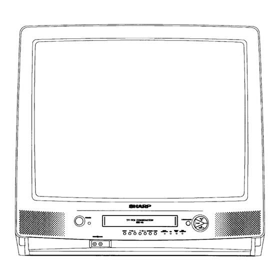
Page 7: Location Of User's Control
25VT-J100 25VT-CJ10 LOCATION OF USER'S CONTROL Description Of Controls FRONT REAR... - Page 8 25VT-J100 25VT-CJ10 LOCATION OF USER'SCONTROL (Continued) Location Of Control’s Buttons (Remote Control)
-
Page 9: Disassembly And Reassembly
25VT-J100 25VT-CJ10 DISASSEMBLY AND REASSEMBLY 1. Remove the 6 rear cover fixing screws and detach the rear cover. 2. Take out the anode cap, CRT PWB, connectors K,M and RC, coating ground SP chip, fixing screws and others. 3. Remove the 2 main PWB fixing screws and take out the main PWB unit and the VCR unit. - Page 10 25VT-J100 25VT-CJ10 DISASSEMBLY AND REASSEMBLY (Continued) 5. Remove the 4 cassette housing control fixing screws, and detach the cassette housing control. 6. Remove the 4 mechanism chassis fixing screws, and detach the mechanism chassis PWB. 7. Remove the 8 main PWB fixing screws, and detach the main PWB.
- Page 11 25VT-J100 25VT-CJ10 DISASSEMBLY AND REASSEMBLY (Continued) For servicing any of the components inside, disconnect the lead dressing holder. Position the main PWB unit upright as shown below and connect the leads for starting the services. Note: Fit the VCR unit into the front cabinet with the front flap door tilted at 70~80°.
-
Page 12: Installation And Service Instructions
25VT-J100 25VT-CJ10 INSTALLATION AND SERVICE INSTRUCTIONS Notes: (1) When performing any adjustments to resistor controls and transformers use non-metallic screwdriver or TV alignment tools. (2) Before performing adjustment, TV set must be on at least 15 minutes. CIRCUIT PROTECTION HIGH VOLTAGE CHECK The receiver is protected by a 4.0A fuse (F701), mounted... -
Page 13: Service Mode
25VT-J100 25VT-CJ10 The J-series SHARP TV/VCR COMBINATION have most of the analog setup adjustments eliminated. Coil and variable resistor adjustments are now performed digitally by using the remote transmitter or set’s volume and channel change function buttons. Note: There are still a few analog adjustments in the J-series such as 120V adjust, focus, master screen voltage and coils in the picture if/detector circuit. - Page 14 25VT-J100 25VT-CJ10 Table-A DATA ADJUSTMENT ADJUSTMENT ITEM INTIAL VALUE RANGE COMMENTS PICTURE 0~63 TINT 0~77 COLOR 0~63 BRIGHT 0~63 SHARP 0~13 V-PHASE H-PHASE 0~31 RF-AGC 0~63 V-AMP 0~63 PIF-VCO 0~127 R CUT-OFF 0~255 G CUT -OFF 0~255 B CUT-OFF 0~255...
-
Page 15: Service Adjustment
25VT-J100 25VT-CJ10 SERVICE ADJUSTMENT White balance adjustment VCO Adjustment 1. Have unit receive a good local channel. 2. Enter the service mode. select service adjustment 1. Connect a digital voltmeter between pin(44) of IC401 “COLOR” and set to “0” ( minimum color) . “COLOR”... - Page 16 25VT-J100 25VT-CJ10 Vertical-size adjustment 1. Have unit receive a good local channel. 2. Enter the service mode and select service adjustment “V-AMP”. 3. While observing the top and bottom of the screen, adjust “V-AMP” data value to proper vertical size and linearity.
-
Page 17: Troubleshooting Of Tv Section
25VT-J100 25VT-CJ10 TROUBLESHOOTING OF TV SECTION... - Page 18 Circuit to be checked: FLOW CHART NO.2-3 FLOW CHART NO.2-4 NO PICTURE, NO SOUND NO VERTICAL SCAN 1. TUNER 2. PIF 3. Automatic gain control 4. 9V power source Does the noise level increase at max, Vertical freq check Abnormal Contrast, Brightness, and Sound Control ? NO Picture NO Sound...
- Page 19 FLOW CHART NO.2-7 FLOW CHART NO.2-5 NO PLAYBACK SOUND NO SOUND Does waveform appear Is there a signal at pin Check the VCR: at pin (54) of IC401 ? (55) of IC401 ? TROUBLESHOOTI NG "NO SOUND". Check IC401 and adjacent parts Does waveform appear Check IC401, and...
-
Page 20: Chassis Layout
25VT-J100 25VT-CJ10 CHASSIS LAYOUT PWB-B CRT UNIT PWB-D VCR KEY UNIT PWB-E POWER SW UNIT PWB-F SENSOR UNIT PWB-C SUB POWER UNIT (25VT-CJ100. ONLY) - Page 21 25VT-J100 25VT-CJ10 MODEL: 25VT-J100 PWB-A MAIN UNIT...
- Page 22 25VT-J100 25VT-CJ10 MODEL: 25VT-CJ10 PWB-A MAIN UNIT...
-
Page 23: Block Diagram Of Tv Section
25VT-J100 25VT-J100 25VT-CJ10 25VT-CJ10 MODEL 25VT-J100 BLOCK DIAGRAM OF TV SECTION... - Page 24 25VT-J100 25VT-J100 25VT-CJ10 25VT-CJ10 MODEL 25VT-CJ10 BLOCK DIAGRAM OF TV SECTION...
- Page 25 25VT-J100 25VT-J100 25VT-CJ10 25VT-CJ10 MODEL 25VT-J100 OVERALL SCHEMATIC DIAGRAM...
- Page 26 25VT-J100 25VT-J100 25VT-CJ10 25VT-CJ10 MODEL 25VT-CJ10 OVERALL SCHEMATIC DIAGRAM...
-
Page 27: Description Of Schematic Diagram
25VT-J100 25VT-J100 25VT-CJ10 25VT-CJ10 DESCRIPTION OF SCHEMATIC DIAGRAM SCHEMATIC DIAGRAM : VCR KEY, POWER SW, CRT, SUB POWER Unit NOTES: WAVEFORM MEASUREMENT CONDITIONS: 1. The unit of resistance "ohm" is omitted 1. Photographs taken on a standard gated color bar (K:1000 ohms, M:1 Meg ohm). - Page 28 25VT-J100 25VT-J100 25VT-CJ10 25VT-CJ10 MODEL 25VT-J100 SCHEMATIC DIAGRAM : MAIN Unit (TV Section)
- Page 29 25VT-J100 25VT-J100 25VT-CJ10 25VT-CJ10...
- Page 30 25VT-J100 25VT-J100 25VT-CJ10 25VT-CJ10 MODEL 25VT-CJ10 SCHEMATIC DIAGRAM : MAIN Unit (TV Section)
- Page 31 25VT-J100 25VT-J100 25VT-CJ10 25VT-CJ10...
- Page 32 25VT-J100 25VT-J100 25VT-CJ10 25VT-CJ10 SCHEMATIC DIAGRAM : MAIN, SENSOR Unit (VCR Section) SENSOR DUNTK9282WEV0. 25VT-J100 DUNTK9282WEV3. 25VT-CJ10 å...
- Page 33 25VT-J100 25VT-J100 25VT-CJ10 25VT-CJ10 SCHEMATIC DIAGRAM : MAIN Unit (VCR Section) DUNTK9282WEV0. 25VT-J100 DUNTK9282WEV3. 25VT-CJ10...
- Page 34 25VT-J100 25VT-J100 25VT-CJ10 25VT-CJ10 PRINTED WIRING BOARD ASSEMBLIES PWB-A: MAIN Unit (Wiring Side)
- Page 35 25VT-J100 25VT-J100 25VT-CJ10 25VT-CJ10 PWB-A: MAIN Unit (Chip Parts Side)
- Page 36 25VT-J100 25VT-J100 25VT-CJ10 25VT-CJ10 PWB-B: CRT Unit (Wiring Side) PWB-F: SENSOR Unit (Wiring Side) PWB-D: VCR KEY Unit (Wiring Side Side) PWB-E: POWER SW Unit (Wiring Side) PWB-C: SUB POWER Unit (Wiring Side) (25VT-CJ10. ONLY)
-
Page 37: Parts List
2. NO. DE REF 3. NO. DE PIECE 4. DESCRIPTION in USA: Contact your nearest SHARP Parts Distributor to order. For in CANADA: Contact SHARP Electronics of Canada Limited location of SHARP Parts Distributor, Please call Toll-Free; Phone (416) 890-2100... - Page 38 25VT-J100 25VT-CJ10 Ref. No. Part No. Description Code Ref. No. Part No. Description Code PWB-A DUNTK9282WEV0/V3 D706 VHD10ELS2//-1 J Diode D707 VHD1SS82///1A J Diode MAIN UNIT (Continued) D710 RH-DX0131CEZZ J Diode å D711 RH-EX0283CEZZ J Zener Diode Q451 VS2SA1037KQ-1 J 2SA1037...
- Page 39 25VT-J100 25VT-CJ10 Ref. No. Part No. Description Code Ref. No. Part No. Description Code PWB-A DUNTK9282WEV0/V3 C209 VCKYCY1HB102K J 1000p 50V Ceramic C210 VCKYCY1CF104Z J 0.1 Ceramic MAIN UNIT (Continued) C211 VCCCCY1HH270J J 27p Ceramic C241 VCEAGA1CW337M J 330 L401 VP-XF120K0000 J Peaking 12µH...
- Page 40 25VT-J100 25VT-CJ10 Ref. No. Part No. Description Code Ref. No. Part No. Description Code PWB-A DUNTK9282WEV0/V3 C2202 VCKYCY1HF103Z J 0.01 Ceramic C2203 VCKYCY1HF103Z J 0.01 Ceramic MAIN UNIT (Continued) C2204 VCKYCY1CF104Z J 0.1 Ceramic C2205 VCEAKA0JW476M J 47 6.3V EL.
- Page 41 25VT-J100 25VT-CJ10 Ref. No. Part No. Description Code Ref. No. Part No. Description Code PWB-A DUNTK9282WEV0/V3 C7701 VCKYCY1HF103Z J 0.01 Ceramic C7702 VCKYCY1HF103Z J 0.01 Ceramic MAIN UNIT (Continued) C7704 VCKYCY1CF104Z J 0.1 Ceramic C7705 VCCCCY1HH220J J 22p Ceramic C3311 VCKYCY1HB471K J 470p...
- Page 42 25VT-J100 25VT-CJ10 Ref. No. Part No. Description Code Ref. No. Part No. Description Code PWB-A DUNTK9282WEV0/V3 R505 VRD-RA2BE101J J 100 1/8W Carbon R506 VRD-RA2BE124G J 120k 1/8W Carbon MAIN UNIT (Continued) R507 VRD-RA2BE104G J 100k 1/8W Carbon R508 VRD-RA2BE473J J 47k 1/8W...
- Page 43 25VT-J100 25VT-CJ10 Ref. No. Part No. Description Code Ref. No. Part No. Description Code PWB-A DUNTK9282WEV0/V3 R2241 VRS-CY1JF183J J 18k 1/16W M.Ox R2244 VRS-CY1JF562J J 5.6k 1/16W M.Ox MAIN UNIT (Continued) R2247 VRS-CY1JF561J J 560 1/16W M.Ox R2248 VRS-CY1JF272J J 2.7k 1/16W M.Ox...
- Page 44 25VT-J100 25VT-CJ10 Ref. No. Part No. Description Code Ref. No. Part No. Description Code PWB-A DUNTK9282WEV0/V3 R7702 VRS-CY1JF102J J 1k 1/16W M.Ox R7703 VRD-RA2BE102J J 1k 1/8W Carbon MAIN UNIT (Continued) R7707 VRD-RA2BE102J J 1k 1/8W Carbon R7708 VRD-RA2BE102J J 1k...
- Page 45 25VT-J100 25VT-CJ10 Ref. No. Part No. Description Code Ref. No. Part No. Description Code PWB-A DUNTK9282WEV0/V3 FH701 QFSHD1017CEZZ J Fuse Holder (25VT-J100) MAIN UNIT (Continued) FH702 QFSHD1018CEZZ J Fuse Holder (25VT-J100) R7796 VRS-CY1JF332J J 3.3k 1/16W M.Ox J401 QJAKF0040CEZZ J AV Input Jack R7797 VRS-CY1JF182J J 1.8k 1/16W M.Ox...
-
Page 46: Crt Unit
25VT-J100 25VT-CJ10 Ref. No. Part No. Description Code Ref. No. Part No. Description Code PWB-B DUNTK9284WEV0 MISCELLANEOUS PARTS P860 QPLGN0461CEZZ J Plug 4-pin (YC) CRT UNIT P880 QPLGN0561CEZZ J Plug 5-pin (GC) TRANSISTIRS SC851 QSOCV0931CEZZ J CRT Socket Q853 VS2SC3619LB1E... - Page 47 25VT-J100 25VT-CJ10 Ref. No. Part No. Description Code Ref. No. Part No. Description Code PWB-D DUNTK9056WEV8 PWB-F DUNTK9066WEV0 VCR KEY UNIT SENSOR UNIT RESISTORS DIODES R2502 VRD-RA2BE103J J 10k 1/8W Carbon ` D7702 RH-PX0252GEZZ J GP1S563 R2503 VRD-RA2BE223J J 22k 1/8W...
- Page 48 25VT-J100 25VT-CJ10 Ref. No. Part No. Description Code Ref. No. Part No. Description Code NPLYV0156AJZZ V Limitter Pulley Ass’y MECHANISM CHASSIS PARTS NROLP0110GEZZ J Guide Roller NSFTP0034AJZZ J Tension Pole Adjuster PGUMM0043AJZZ V Damper Raber LBNDK1009AJZZ V Tension Band Ass’y...
- Page 49 25VT-J100 25VT-CJ10 Ref. No. Part No. Description Code Ref. No. Part No. Description Code MECHANISM CHASSIS PARTS...
- Page 50 25VT-J100 25VT-CJ10 Ref. No. Part No. Description Code Ref. No. Part No. Description Code SCREW, NUT AND WASHERS CASSETTE HOUSING CONTROL PARTS LX-XZ3030GEFD J Screw CHLDX3074TEV0 V Cassette Housing XBPSD26P08000 J Screw Control Ass’y LX-HZ3082GEZZ J Audio/Control Head LANGF9592AJFW V Upper Plate...
- Page 51 25VT-J100 25VT-CJ10 Ref. No. Part No. Description Code Ref. No. Part No. Description Code CASSETTE HOUSING CONTROL PARTS...
- Page 52 - Not Available - – Cabinet-Front — LHLDW1019PEKZ R Wire Holder GCOVA0052PESA R Cover, R/C. LHLDW0017PEKZ R Wire Holder HBDGB1008MESA M Badge, SHARP å QACCD3042CESA J AC Cord HDECQ0079PESA R LED Decoration (25VT-J100) HDECQ0081PESC M Cassette Flap-Door LHLDW1008MEKZ M Degausing Coil Holder...
- Page 53 25VT-J100 25VT-J100 25VT-CJ10 25VT-CJ10 CABINET AND MECHANICAL PARTS...
-
Page 54: Packing Of The Set
25VT-J100 25VT-J100 25VT-CJ10 25VT-CJ10 Ref. No. Part No. Description Code Ref. No. Part No. Description Code PACKING OF THE SET • SETTING POSITIONS OF THE KNOBS PACKING PARTS SUPLLIED ACSESSORIES Power SW (NOT REPLACEMENT ITEM) Channel RRMCG1330PESA R Infrared R/C Unit SPAKC0551MEZZ –... - Page 55 25VT-J100 25VT-CJ10 Memo...
- Page 56 25VT-J100 25VT-CJ10 TQ0276-S YO. KG Printed in U.S.A...
Need help?
Do you have a question about the 25VT-J100 and is the answer not in the manual?
Questions and answers