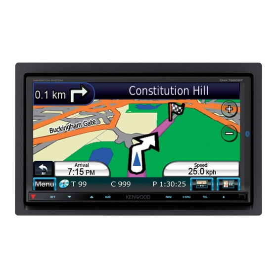
Kenwood DNX7260BT Installation Manual
Dnx series
Hide thumbs
Also See for DNX7260BT:
- Instruction manual (116 pages) ,
- Instruction manual (112 pages) ,
- Instruction manual (26 pages)
Table of Contents
Advertisement
GPS NAVIGATION SYSTEM
SYSTÈME DE NAVIGATION GPS
GPS-NAVIGATIONSSYSTEM
GPS-NAVIGATIESYSTEEM
SISTEMA DI NAVIGAZIONE GPS
SISTEMA DE NAVEGACIÓN GPS
SISTEMA DE NAVEGAÇÃO GPS
DNX SERIES
DNX7260BT
INSTALLATION MANUAL
MANUEL D'INSTALLATION
INSTALLATION-HANDBUCH
INSTALLATIEHANDLEIDING
MANUALE DI INSTALLAZIONE
MANUAL DE INSTALACIÓN
MANUAL DE INSTALAÇÃO
© B54-4777-00/00 (EW)
Advertisement
Table of Contents

Summary of Contents for Kenwood DNX7260BT
- Page 1 GPS NAVIGATION SYSTEM SYSTÈME DE NAVIGATION GPS GPS-NAVIGATIONSSYSTEM GPS-NAVIGATIESYSTEEM SISTEMA DI NAVIGAZIONE GPS SISTEMA DE NAVEGACIÓN GPS SISTEMA DE NAVEGAÇÃO GPS DNX SERIES DNX7260BT INSTALLATION MANUAL MANUEL D'INSTALLATION INSTALLATION-HANDBUCH INSTALLATIEHANDLEIDING MANUALE DI INSTALLAZIONE MANUAL DE INSTALACIÓN MANUAL DE INSTALAÇÃO © B54-4777-00/00 (EW)
-
Page 2: Accessories Installation Procedure
Accessories Installation Procedure 1. To prevent short circuits, remove the key from the ignition and disconnect the - terminal of the battery. 2. Make the proper input and output wire ..1 connections for each unit. 3. Connect the wire on the wiring harness. 4. - Page 3 is due to the characteristics of a mechanism • Insulate unconnected wires with vinyl tape or other similar material. To prevent a short circuit, the product is equipped with. do not remove the caps on the ends of the If the program that is activated when the unconnected wires or the terminals.
- Page 4 Connect to the terminal that is grounded when either the telephone rings or during conversation. ⁄ To connect the Kenwood navigation system, consult your navigation manual. Connect either to the power control terminal when using the optional power amplifier, or to the antenna control terminal in the vehicle.
- Page 5 Bluetooth Microphone (Accessory 9) (see page 9) Cooling fan GPS Antenna (Accessory 7) (see page 9) FUSE (15A ) Accessory 1 Reverse sensor wire (Purple/White) REVERSE Steering remote control input (Light Blue/Yellow) STEERING WHEEL REMOTE CONT REMOTE INPUT Mute control wire (Brown) MUTE Power control/ Motor antenna control wire (Blue/White) ANT.
-
Page 6: Connecting Wires To Terminals
Connecting Wires to Terminals 2WARNING Connector Function Guide Pin Numbers for Cable Colour Functions Connecting the ISO Connector ISO Connectors The pin arrangement for the ISO connectors External Power depends on the type of vehicle you drive. Make sure Connector to make the proper connections to prevent damage Yellow Battery... -
Page 7: System Connection
System Connection USB device or iPod (commercially available) USB terminal Audio input (iPod/AV Input 2 switchable) Resistance-free stereo type mini plug (3.5φ) Visual input (iPod/AV Input 2 switchable) Resistance-free mini plug (3.5φ) Accessory 4 Accessory 3 Accessory 2 Audio/Visual Output •... -
Page 8: Optional Accessory Connection
Optional Accessory Connection iPod (commercially available) KCA-iP301V (Optional Accessory) Visual Output (Yellow) Audio Output (Black) USB terminal USB terminal TV Tuner (Optional Accessory) Connection cable (Included in the TV tuner) DNX SERIES... -
Page 9: Installing The Gps Antenna
Installing the Microphone Installing the GPS Antenna Unit GPS antenna is installed inside of the car. It 1. Check the installation position of the should be installed as horizontally as possible microphone (accessory 9). to allow easy reception of the GPS satellite 2. -
Page 10: Installation For Monitor/Player Unit
Installation for Monitor/Player Unit Installing the Escutcheon Attaching the monitor panel 1. Attach accessory 6 to the unit. Accessory 0 Hold the monitor panel securely so as not to drop it accidentally. Fit the monitor panel onto the attaching Accessory 6 plate until it is firmly locked. -
Page 11: Removing The Unit
Removing Monitor/Player Unit Removing the Hard Rubber Removing the Unit Frame (escutcheon) 1. Remove the hard rubber frame by referring to the removal procedure in the section 1. Engage the catch pins on the removal tool <Removing the Hard Rubber Frame>. 5 and remove the two locks on the lower 2.


Need help?
Do you have a question about the DNX7260BT and is the answer not in the manual?
Questions and answers