Table of Contents
Advertisement
Available languages
Available languages
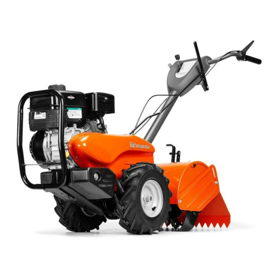
Operator's Manual
Gasoline containing up to 10% ethanol (E10) is accept-
able for use in this machine. The use of any gasoline ex-
ceeding 10% ethanol (E10) will void the product warranty.
Manuel de L'Opérateur
Vous pouvez utiliser de l'essence contenant jusqu'à
10 % d'éthanol (E10) avec cet appareil. L'utilisation
DRT900 / 960930025
d'essence contenant plus de 10 % d'éthanol annulera
la garantie du produit.
Please read the operator's manual carefully and make sure
you understand the instructions before using the machine.
115 66 38-32 Rev. 2
Lisez très attentivement et soyez certain de comprende
English/French
ces instructions avant d'utiliser cette machine.
Advertisement
Chapters
Table of Contents

Related Manuals for Husqvarna DRT900


Summary of Contents for Husqvarna DRT900
- Page 1 Manuel de L’Opérateur Vous pouvez utiliser de l’essence contenant jusqu’à 10 % d’éthanol (E10) avec cet appareil. L’utilisation DRT900 / 960930025 d’essence contenant plus de 10 % d’éthanol annulera la garantie du produit. Please read the operator's manual carefully and make sure you understand the instructions before using the machine.
-
Page 2: Safety Rules
SAFETY RULES Safe Operation Practices for Walk-Behind Powered Ro ta ry Tillers TRAINING • Never operate the tiller without proper guards, plates, or other safety protective devices in place. • Read the Manual care ful ly. Be thor ough ly fa mil iar with •... -
Page 3: Table Of Contents
PRODUCT SPECIFICATIONS CUSTOMER RESPONSIBILITIES • Read and observe the safety rules. Gasoline Capacity: 3.2 Quarts • Follow a regular schedule in maintaining, caring for Unleaded Reg u lar and using your tiller. Oil (API-SG-SL): SAE 30 Above 32°F/0°C • Follow instructions under “Maintenance” and “Stor age” (Capacity: 20 oz.) SAE 5W30 Below 32°F/0°C sections of this Owner’s Manual. -
Page 4: Assembly
ASSEMBLY Your new tiller has been assembled at the factory with exception of those parts left unassembled for shipping purposes. To ensure safe and proper operation of your tiller all parts and hardware you assemble must be tightened securely. Use the correct tools as necessary to insure proper tightness. - Page 5 ASSEMBLY UNPACKING CARTON (See Fig. 2) • Grasp handle assembly. Hold in “up” position. Be sure handle lock remains in gearcase notch. Slide handle assembly into position. CAUTION: Be careful of exposed sta ples when handling or disposing of cartoning material. HANDLE ASSEMBLY "UP"...
- Page 6 ASSEMBLY CONNECT SHIFT ROD (See Fig. 7) REMOVE TILLER FROM CRATE • Insert end of shift rod into hole of shift lever indicator. • Make sure shift lever indicator is in “N” position (See Fig. 7) • Insert hairpin clip through hole of shift rod to secure. •...
-
Page 7: Operation
OPERATION KNOW YOUR TILLER READ THIS OWNER'S MANUAL AND SAFETY RULES BEFORE OPERATING YOUR TILLER. Compare the illustrations with your tiller to familiarize yourself with the location of various controls and adjustments. Save this manual for future reference. These symbols may appear on your Tiller or in literature supplied with the product. Learn and understand their meaning. -
Page 8: To Use Tiller
OPERATION The operation of any tiller can result in foreign objects thrown into the eyes, which can result in severe eye damage. Always wear safety glasses or eye shields before starting your tiller and while tilling. We recommend a wide vision safety mask for over spectacles or standard safety glasses. 00155 HOW TO USE YOUR TILLER Know how to operate all controls before adding fuel and... - Page 9 OPERATION TO TRANSPORT DEPTH STAKE PIN “RELEASED” POSITION CAUTION: Before lifting or trans port- ing, allow tiller engine and muffler to cool. Disconnect spark plug wire. Drain gasoline from fuel tank. AROUND THE YARD • Release the depth stake pin. Move the depth stake down to the top hole for transporting the tiller.
- Page 10 OPERATION ADD GASOLINE • When engine starts, slowly move choke control to “RUN” position as engine warms up. • Fill fuel tank to bottom of filler neck. Do not overfill. NOTE: A warm engine requires less choking to start. Use fresh, clean, regular un lead ed gasoline with a •...
- Page 11 OPERATION • Do not lean on handle. This takes weight off the wheels ADJUST WHEELS FOR CULTIVATING and reduces traction. To get through a really tough (See Figs. 17 and 18) section of sod or hard ground, apply upward pressure •...
-
Page 12: Maintenance Schedule
MAINTENANCE MAINTENANCE SCHEDULE FILL IN DATES AS YOU COMPLETE SERVICE DATES REGULAR SERVICE Check Engine Oil Level Change Engine Oil Oil Pivot Points Inspect Spark Arrester / Muffler Inspect Air Screen Clean or Replace Air Cleaner Cartridge Clean Engine Cylinder Fins Replace Spark Plug RH Gear Case Grease Fitting (1oz.) 1 - Change more often when operating under a heavy load or in high ambient temperatures. -
Page 13: Maintenance
MAINTENANCE Disconnect spark plug wire before performing any maintenance (except car bu re tor adjustment) to prevent accidental start ing of engine. Prevent fires! Keep the engine free of grass, leaves, spilled oil, or fuel. Re move fuel from tank before tipping unit for maintenance. -
Page 14: Spark Plug
MAINTENANCE COOLING SYSTEM (See Fig. 22) SPARK PLUG Your engine is air cooled. For proper engine performance Replace spark plugs at the beginning of each tilling sea- and long life keep your engine clean. son or after every 50 hours of use, whichever comes first. Spark plug type and gap setting is shown in “PRODUCT •... -
Page 15: Service And Adjustments
SERVICE AND ADJUSTMENTS CAUTION: Disconnect spark plug wire from spark plug and place wire where it cannot come into contact with plug. TILLER TO ADJUST HANDLE HEIGHT (See Fig. 23) Select handle height best suited for your tilling conditions. CLEVIS PIN Handle height will be different when tiller digs into soil. -
Page 16: Ground Drive Belt Adjustment
SERVICE AND ADJUSTMENTS TO REPLACE GROUND DRIVE BELT GROUND DRIVE BELT ADJUSTMENT (See Figs. 25 and 26) (See Fig. 26) • Remove belt guard as described in “TO REMOVE BELT For proper belt tension, the extension spring should have GUARD”. about 5/8 inch (16 mm) stretch when drive control bar is in “EN GAGED”... -
Page 17: Tine Replacement
SERVICE AND ADJUSTMENTS ma chine the tines should be checked for sharpness, TINE REPLACEMENT wear, and bending, particularly the tines which are (See Figs. 27, 28 and 29) next to the transmission. If the gap between the tines ex ceeds 3-1/2" they should be replaced or straight ened CAUTION: Tines are sharp. -
Page 18: See Fig
SERVICE AND ADJUSTMENTS ENGINE TO AD JUST CARBURETOR The carburetor has been preset at the factory and is not TO ADJUST THROTTLE CONTROL CABLE adjustable. (See Fig. 30) IMPORTANT: NEVER TAMPER WITH THE ENGINE GOVERNOR, WHICH IS FACTORY SET FOR PROPER ENGINE SPEED. OVER- The throttle control has been preset at the factory and SPEED ING THE ENGINE ABOVE THE FACTORY HIGH SPEED ad just ment should not be necessary. -
Page 19: Storage
STORAGE Immediately prepare your tiller for storage at the end of the ENGINE OIL season or if the unit will not be used for 30 days or more. Drain oil (with engine warm) and replace with clean oil. (See “ENGINE” in the Maintenance section of this man ual). CAUTION: Never store the tiller with gasoline in the tank inside a build ing where fumes may reach an open flame... -
Page 20: Troubleshooting
TROUBLESHOOTING POINTS PROBLEM CAUSE CORRECTION Will not start 1. Out of fuel. Fill fuel tank. 2. Engine not “CHOKED” properly. See “TO START ENGINE” in the Operation section. 3. Engine flooded. Wait several minutes before attempting to start. 4. Dirty air cleaner. Clean or replace air cleaner cartridge. - Page 21 (a) Engines and Attachments.Except where otherwise indicated on Exhibit A, all Engines and Attachments are not covered by this Limited Warranty. In most cases, these items are NOT manufactured by Husqvarna in which case they may be covered separately by their respective manufacturer's warranties if one is provided and included with the product at the time of purchase.
- Page 22 10. Authorized Husqvarna Servicing Dealer/Center. In order to obtain warranty coverage it is your responsibility (at your expense) to deliver or ship your Husqvarna unit to an authorized Husqvarna Servicing Dealer/Center and arrange for pick-up or return of your unit after the repairs have been made.
-
Page 23: Warranty
Riding Lawn Tractors: Frame, Chassis, Front Axle 5 Years No Warranty No Warranty Engine* Transmission (if made by Husqvarna/Peerless) 3 Years No Warranty No Warranty Transmission (if third party)** XLS Models only - stamped deck shell. Armor Protected Limited Warranty... - Page 24 ** See reference 1 (b) of the warranty statement. RZ - Two (2) Year Consumer warranty, parts & labor, with Hydro-Gear Distributor network. EZ - One (1) Year Commercial warranty, parts & labor, with Husqvarna. Two (2) Year Consumer warranty, parts & labor, with Hydro-Gear Distributor network.
-
Page 25: Règles De Sécurité
RÈGLES DE SÉCURITÉ Conseils pour l'Utilisation en toute Sécurité des Motobineuses FORMATION: • Ne laissez jamais la motobineuse à grande vi tes se quand la surface est glissante. Regardez en arrière et soyez prudent • Lisez soigneusement ce manuel du propriétaire. Fa mi lia ri- en reculant. -
Page 26: Responsabilités Du Client
SPÉCIFICATIONS DE PRODUIT RESPONSABILITÉS DU CLIENT • Lisez et faites attention aux règles de sécurité. Capacité et type d'essence: 3.2 Qts. de Gallon • Suivez un programme habituel d’entretien, de soin, et d’uti- L'essence sans plomb normale li sa tion de la motobineuse. Type d'huile (API-SF-SJ) SAE30 (à... -
Page 27: Montage
MONTAGE Votre nouvelle motobineuse a été montée à l'usine sauf certaines pièces en vue de l'expédition. Pour s'assurer d'une utilisation correcte et sûre de votre motobineuse, toutes les pièces et ferrures que vous assemblez doivent être serrées à fond. Utilisez les bons outils. LES OUTILS EXIGES POUR LE MONTAGE DEVANT Un jeu des clés à... - Page 28 MONTAGE • Empoignez l’ensemble de poignée. Le tenez en po si tion DEBALLER LE CARTON (Voir la fig. 2) "hau te". Assurez que le verrou de poignée reste dans l’en co che de la boîte de vitesse. Glissez l’ensemble de ATTENTION: Faites attention aux agrafes du poi gnée en position.
- Page 29 MONTAGE ATTACHER LE CABLE D’EMBRAYAGE RACCORDER LA TIGE DE CHANGEMENT DE (Voir la fig. 6) VI TES SE (Voir la fig. 7) • Accrochez l'extrémité du câble d'embrayage à travers du • Insérez l’extrémité de la tige de changement de vitesse dans trou dans le support de la barre de commande au besoin.
-
Page 30: Utilisation
UTILISATION CONNAISSEZ VOTRE MOTOBINEUSE LISEZ CE MANUEL DU PROPRIÉTAIRE ET LES RÈGLES DE SÉCURITÉ AVANT D’UTILISER VOTRE MOTOBINEUSE. Comparez les illustrations à votre motobineuse pour connaître les positions des différentes commandes et les différents réglages. Conservez ce manuel. Ces symboles peuvent se montrer sur votre motovineuse à gazon ou dans les publications fournies avec le produit. Apprenez et comprenez la signification des symboles. - Page 31 UTILISATION L’utilisation d’une motobineuse présente le risque de la projection des particules dans les yeux, ce qui peut causer des blessures sérieuses. Portez toujours des lunettes de sécurité ou une visière avant de démarrer la motobineuse et lorsque vous labourez. Nous recommandons une visière de sécurité pa no ra mi que pour ceux qui portent des lunettes ou des lunettes de sécurité...
- Page 32 UTILISATION IMPORTANT: RELÂCHEZ TOUJOURS LA BARRE DE POUR TRANSPORTER COMMANDE D’ENTRAÎNEMENT AVANT DE DÉPLACER LE LEVIER DE CHANGEMENT DE VITESSE À UNE AUTRE ATTENTION: Laissez refroidir le moteur et le POSITION. silen cieux avant de soulever ou transporter. Dé- branchez le fil de bougie d’allumage. Vidangez "SERRER"...
- Page 33 UTILISATION REMPLIR LE RÉSERVOIR D’ESSENCE • Si le moteur ne démarre pas, bougez la commande de star- ter a demi-position. Tirez la poignée de démarrage (recul) • Remplissez le réservoir d’essence. Remplissez le réservoir jusqu'à ce que le moteur démarre. d’es sen ce jusqu’au fond de son goulot de rem plis sa ge.
- Page 34 UTILISATION • Vous trouverez le labourage beaucoup plus facile si vous RÉGLER LES ROUES POUR BINER (Voir les laissez un sillon non bêché entre les passes. En ce temps- fig. 17 et 18) la retourner entre le rang de labourage (Voir la fig. 15). Il y a deux raisons pour faire ceci.
-
Page 35: Calendrier D'entretien
ENTRETIEN CALENDRIER D’ENTRETIEN INSCRIVEZ LES DATES AU FUR ET À MESURE QUE VOUS EFFECTUEZ LES ENTRETIENS DATES D’ENTRETIEN RÉGULIERS Vérifiez le niveau d’huile de moteur Changez l’huile de moteur Huilez les points de pivotement Inspectez le silencieux pare-étincelles Inspectez le tamis à air Nettoyez/remplacez la cartouche du filtre à... -
Page 36: Entretien
ENTRETIEN MOTEUR FILTRE À AIR (Voir la fig. 21) Votre moteur ne marche pas correctement avec un filtre à air LUBRIFICATION sale. Nettoyez l'élément du pré-filtre en mousse toutes les 25 heures d'utilisation ou chaque saison. Entretenez la car tou che Utilisez seulement l'huile déterente de qualité... - Page 37 ENTRETIEN SILENCIEUX SYSTÈME DE REFROIDISSEMENT (Voir la fig. 22) N’utilisez pas la motobineuse sans silencieux. Ne modifiez pas le système d’échappement. Un silencieux ou un pare-étincelles Votre moteur est refroidi à l'air. Pour un bon fonctionnement du avarié pose des risques d’incendie. Inspectez-les pé rio di que ment moteur et pour une longue durabilité, maintenez le moteur propre.
-
Page 38: Révision Et Réglages
RÉVISION ET RÉGLAGES ATTENTION: Débranchez le fil de bougie d'allumage et posez-le à un endroit où il ne peut pas toucher la bougie. MOTOBINEUSE POUR RÉGLER LA HAUTEUR DU GUIDON (Voir la fig. 23) AXE DE CHAPE Choisissez la hauteur la plus convenable pour vous et les condi- tions de labourage. - Page 39 RÉVISION ET RÉGLAGES POUR REMPLACER LA COURROIE RÉGLER LA COURROIE D’ENTRAÎNEMENT D’ENTRAÎNEMENT À TERRE À TERRE (Voir la fig. 26) (Voir figs. 25 et 26) Pour la tension de courroie correcte, le ressort de traction devrait avoir approximativement un allongement de 5/8 po. (16 mm) •...
- Page 40 RÉVISION ET RÉGLAGES REMPLACEMENT DES FRAISES • Pour conserver cette machine en bon fonctionnement, il convient d’inspecter les fraises du point de vue de l’acuité, (Voir les fig. 27, 28, et 29) de l’usure et du gauchissement, en particulier les fraises qui se trouvent à...
- Page 41 RÉVISION ET RÉGLAGES MOTEUR POUR RÉGLER LE CARBURATEUR Le carburateur a été réglé à l’usine et non modifiable. POUR RÉGLER LE CÂBLE DE LA COM MAN DE IMPORTANT: NE TOUCHEZ PAS LE REGULATEUR DE DES GAZ (Voir Fig. 30) MOTEUR. LE CONSTRUCTEUR DE L’EQUIPEMENT QUI A MONTE LE MOTEUR DETERMINE LA VITESSE MAXIMUM HORS La commande des gaz a été...
-
Page 42: Entreposage
ENTREPOSAGE Préparez immédiatement votre motobineuse pour l’en tre po sa ge HUILE DE MOTEUR à la fin de la saison ou si l'unité ne sera pas utilisée pendant 30 Vidangez l’huile (quand le moteur est chaud) et rem placez avec jours ou plus. -
Page 43: Guide De Dépannage
GUIDE DE DÉPANNAGE PROBLEME CAUSE CORRECTION Le moteur refuse Sans essence. Remplissez le réservoir d’essence. de démarrer Le moteur n’est pas correctement étranglé. Référez-vous à la section “DÉMARRER LE MOTEUR” dans la section d’utilisation. Le moteur est noyé. Attendez plusieurs minutes avant de démarrer. Filtre à... - Page 44 / boîte-pont, Dana, Hydro-Gear, Tuff-Torq, offrent une garantie sur la transmission ou la boîte-pont à l’acheteur fi nal ou à Husqvarna. Husqvarna assignera par la suite la garantie du fabricant sur la transmission / boîte-pont, ou tout droit à cet égard, à l’acheteur original de l’appareil.
- Page 45 été effectuées. Si vous ne connaissez pas l’emplacement du centre de service agréé ou un dépositaire Husqvarna au 1 800 487 5951 entre 8 h et 20 h (HNE), ou visitez www.husqvarna.com. Si vous avez besoin d’aide ou si vous avez des questions con- cernant cette garantie limitée, vous pouvez communiquer avec nous au 800 487 5951 entre 8 h et 20 h (HNE) ou au 800 805 5523 (Canada) entre 8 h...
-
Page 46: Garantie
Tondeuses à siège : Cadre, châssis, essieu avant 5 ans Aucune garantie Aucune garantie Moteur* Husqvarna/Peerless) 3 ans Aucune garantie Aucune garantie Transmission (si tierce partie)** Modèless XLS Models uniquement - coque d'unité de coupe étampée. Garantie limitée de la... - Page 47 RZ – Deux (2) ans de garantie au consommateur, pièces et main-d'oeuvre, auprès du réseau de distributeurs Hydro-Gear. EZ – Un (1) an de garantie commerciale, pièces et main-d'oeuvre, auprès de Husqvarna. Deux (2) ans de garantie au consommateur, pièces et main-d'oeuvre, auprès du réseau de distributeurs Hydro-Gear.
- Page 48 01/31/2014 BY...
Need help?
Do you have a question about the DRT900 and is the answer not in the manual?
Questions and answers