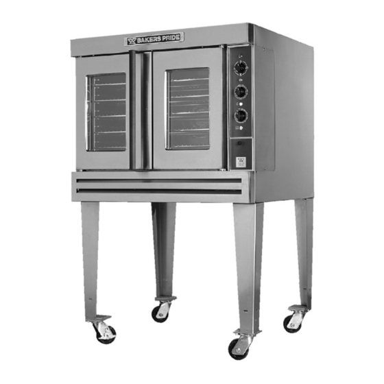
Bakers Pride CO11-G Installation And Operating Instructions Manual
Gas convection oven
Hide thumbs
Also See for CO11-G:
- Installation and operating instructions manual (20 pages) ,
- Parts list (4 pages) ,
- Catalog (72 pages)
Table of Contents
Advertisement
Quick Links
INSTALLATION AND OPERATING INSTRUCTIONS
GAS CONVECTION OVEN
RETAIN THIS MANUAL FOR FUTURE REFERENCE
OVEN MUST BE KEPT CLEAR OF COMBUSTIBLES AT ALL TIMES
After the gas supply has been connected to your unit, it is extremely important to check piping for possible
leaks. To do this, use soap and water solution or solutions which are expressly made for this purpose.
DO NOT USE
matches, candles, flames, or other sources of ignition since these methods are extremely
dangerous. Post in a prominent location instructions to be followed in the event you smell gas. Obtain these
instructions from your local gas supplier.
FOR YOUR SAFETY:
!
vapors and liquids in the vicinity of this or any other appliance.
WARNING:
!
maintenance can cause property damage, injury or death. Read the Installation,
Operating and Maintenance Instructions thoroughly before installing or servicing
this equipment.
Initial heating of oven may generate smoke or fumes and must be done in a well-ventilated area.
Overexposure to smoke or fumes may cause nausea or dizziness.
Note: Only
Pizza
or
Bread
placed in a pan or container to avoid direct contact with ceramic decks.
This equipment has been engineered to provide you with year round dependable service when used
according to the instructions in this manual and standard commercial kitchen practices.
+1 (914) 576-0200 Phone
+1 (914) 576-0605 Fax
Model: CO11-G
INTENDED FOR OTHER THAN HOUSEHOLD USE
IMPORTANT INSTRUCTIONS
Do not store or use gasoline or other flammable
Improper installation, adjustment, alteration, service or
can have direct contact with ceramic decks. All other food products must be
BAKERS PRIDE OVEN CO., INC.
30 Pine Street
New Rochelle, NY 10801
BAKERS
PRIDE
www.bakerspride.com
info@bakerspride.com e-mail Address
1
P/N U4151A 05/04
(800) 431-2745
US & Canada
Web Address
!
!
Advertisement
Table of Contents

Related Manuals for Bakers Pride CO11-G


Summary of Contents for Bakers Pride CO11-G
-
Page 1: Important Instructions
This equipment has been engineered to provide you with year round dependable service when used according to the instructions in this manual and standard commercial kitchen practices. P/N U4151A 05/04 BAKERS PRIDE OVEN CO., INC. 30 Pine Street New Rochelle, NY 10801... -
Page 2: Table Of Contents
TABLE OF CONTENTS I. INSTALLATION INSTRUCTIONS SECTION ITEM PAGE Receiving Set-Up Mounting Installation with Casters (Optional) Location and Minimum Clearances Gas Connection Electrical Connection Flue Connections-Ventilation Burner Operation System Check: Rotary Control II. OPERATING INSTRUCTIONS General Instructions System Operation Sequence A) Cook Only B) Timed Cooking C) Cook &... -
Page 3: Receiving
Line up sides and front of both ovens and fasten to each other with stacking brackets. All legs for the CO11-G 1 and CO11-G2 as well as the base cabinet have a leveling adjustment. Start with adjustment screwed all the way in. With a spirit Ievel placed on an oven rack, check and level side to side first and then front to back. -
Page 4: Installation With Casters (Optional)
Position 'Rack Supports' and tighten in place using 4 each of Flat washers and 5/16-18 Hex Nuts. To assemble over a Base Cabinet: (1 ) Tilt cabinet over onto the left hand side. Attach two mounting plates to the right underside and screw 6"... -
Page 5: Electrical Connection
Use a pipe joint compound that is resistant to the action of liquefied petroleum gases when making gas Connections. For Propane gas, use at least 1/ 2" (13 mm) pipe or tubing with a 5/8" (16 mm) inside diameter. For Natural gas, use 3/4" (19 mm) pipe. The gas pressure regulator is part of the combination valve and is adjusted to yield a pressure of 3.5"... -
Page 6: Burner Operation
extending out of the building. The flue pipe from the draft hood must not run downwards at any point from the oven to the final outlet. It should always slant slightly upwards. For best results it should rise straight up NOTE: DO NOT PUT A DAMPER IN THE FLUE AND DO NOT CONNECT A BLOWER DIRECTLY TO THE FLUE. -
Page 7: System Operation Sequence
2. OPERATION SEQUENCE-ROTARY CONTROL: A. COOK ONLY-ROTARY CONTROL: Close the oven doors. Turn Selector Switch to 'HI' or 'LO' position. The indicator light near the Selector Switch will be illuminated. Turn the thermostat knob to the desired cooking temperature. Upon reaching the set temperature, the indicator light near the thermostat will go out. Load the oven with product to be cooked. -
Page 8: Cleaning
3. CLEANING: CLEAN ONLY WHEN OVEN IS COLD With porcelain enamel interiors, this oven is designed to be as maintenance free as possible. However for best results the oven should be cleaned regularly. Enameled interiors can be easily cleaned with oven cleaners. KEEP CLEANING FLUIDS A WAY FROM ELECTRIC WIRES, LIGHT SOCKETS, SWITCHES AND CONTROL PANEL. - Page 9 5. ILLUSTRATIONS (CONTINUED) Fig. 5 Fig. 3 WHEEL PULLER BOLT 3/8”-HEX BLOWER WHEEL CONTROL PANEL (ROTARY CONTROL) MOTOR SELECTOR SWITCH PILOT LIGHT SET SCREW (2) (GREEN) SELECTOR Fig. 4 SWITCH ASSEMBLY OF LEGS (SHOWN WITH OPEN RACK STAND) 3/8”-16 x 3/4” 30”...
-
Page 10: Electrical Schematic - Rotary Control
6. CO11-G ELECTRICAL SCHEMATIC (ROTARY CONTROL) Power 120VAC Coil X 0...60' Timer O 0 - TIMER M450 X 0 - O 0...60' BUZZER Steam Potentiometer Factory Set (8 Seconds) Coil SSAC Steam Solenoid Button Valve NOTO 120V ground Ignition Valve... -
Page 11: Wiring Diagram - Rotary Control
7. CO11-G WIRING DIAGRAM (ROTARY CONTROL) 120VAC steam switch potentiometer timer M450 solenoid valve 120v ignitor L1-24vac ignitor thermostat valve hot ground flame sensor combination control VR 8205 flame rod Pilot Light (Thermostat) Rotary Switch Pilot Light (Power) light switch... -
Page 12: Wiring Diagram - Programmable Control
8. CO11-G WIRING DIAGRAM (w/PROGRAMMABLE CONTROLS) C&H-3 W T [2] 120 V BLK [11] BRW N [ ] BRW N [ ] BLK [13] Rotary BLK [1] Switch 120 V W T [ ] 2 Speed M otor W T [S1]... -
Page 13: Replaceable Parts List
9. PARTS LISTS & EXPLODED VIEWS CO11-G 30 Pine Street • New Rochelle • New York • 10801 914 / 576 - 0200 914 / 576 - 0605 BAKERS 1 - 800 - 431 - 2745 US & Canada PRIDE Full Size Gas Convection Oven www.bakerspride.com... - Page 14 CO11-G 30 Pine Street • New Rochelle • New York • 10801 914 / 576 - 0200 914 / 576 - 0605 BAKERS 1 - 800 - 431 - 2745 US & Canada PRIDE Full Size Gas Convection Oven www.bakerspride.com...
- Page 15 Flue Diverter (For Direct Venting) Q3008A Flat Washer (4) R3167A Flue Diverter (For Collection Hood) Q3014A Lock Washer, Split (4) U1043X Bakers Pride Name Plate (13 3/4") Q2204A Nut, 5/16 HX, 5/16-18 (4) U1290A Control Panel Overlay (Rotary) S1195X Blower Wheel...
-
Page 16: Warranty
BAKERS PRIDE Factory Authorized Service Center. This Warranty is in lieu of all other warranties, expressed or implied, and all other obligations or liabilities on the manufacturers part. BAKERS PRIDE shall in no event be liable for any special, indirect or consequential damages, or in any event for damages in excess of the purchase price of the unit. The repair or replacement of proven defective parts shall constitute a fulfillment of all obligations under the terms of this warranty.
Need help?
Do you have a question about the CO11-G and is the answer not in the manual?
Questions and answers