DuraMax Metal Garden Shed Owner's Manual
Pent roof type size 6’ x 4'
Hide thumbs
Also See for Metal Garden Shed:
- Owners manual and assembly (33 pages) ,
- Owner's manual/ instructions for assembly (44 pages) ,
- Owner's manual (49 pages)
Table of Contents
Advertisement
A L L
P U R P O S E
M E T A L
S T O R A G E
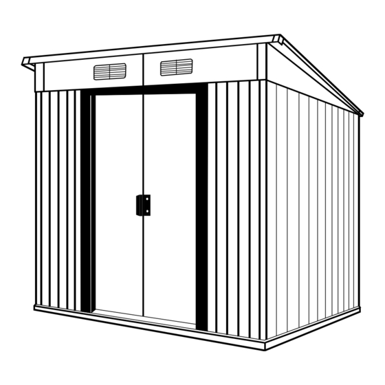
Pent Roof Type
Metal Garden Shed
OWNER' S MANUAL /
Instructions for Assembly
Size 6' x 4'
Ver: 1.0
• Tall Walk in Shed
• Quick & Easy Assembly
• Ridge Reinforced Walls
• Wide Double Doors
• Available in Various Sizes
S H E D S
Requires two people and takes 2-3 hours for Installation.
Customer
Service Hotline
(800) 483-4674
www.uspolymersinc.com
Call us for any missing or damaged par ts.
Do not return to the store.
Advertisement
Table of Contents

Related Manuals for DuraMax Metal Garden Shed


Summary of Contents for DuraMax Metal Garden Shed
- Page 1 P U R P O S E M E T A L S T O R A G E S H E D S Pent Roof Type Metal Garden Shed OWNER’ S MANUAL / Instructions for Assembly Size 6’ x 4’ Ver: 1.0...
-
Page 2: Parts List
Parts List Note: Check all par ts prior to installation. ACCESSORIES CODE DESCRIPTION CODE DESCRIPTION PROFILES BASE BAR BOTTOM SLIDER BACK LEFT BASE BAR DOOR HANDLE BACK RIGHT TOP CORNER BASE BAR SIDE LEFT & RIGHT TOP SLIDER BBFC BASE BAR FRONT LEFT &... -
Page 3: Exploded View
Exploded View RFSLR RFRC RPSLR RPCLR RFLC RFLC RPCLR RPSLR RFRC GPSL RFSLR SBSLR RSLR GPCLR GPSLR SBSLR FB1C RSLR GPCLR SBSLR GPSLR GPSLR FB2C GPSR ASLR ABLR ABLR WCBC ASLR WCFC BBFC WFLC WCBC BBFC WCFC WFRC DCLC DCRC DPLC DPRC IMPORTANT: USE HAND GLOVES TO PREVENT INJURY. - Page 4 Duramax Storage Shed Limited Fifteen Year Warranty U.S. Polymer Inc. will send a replacement part free of charge, in the event of material defects and or workmanship for a period of fifteen years from the date of purchase. This warranty is extended only to the original purchaser. A purchase receipt or other proof of date of original purchase will be required before warranty service is rendered.
- Page 5 3ea 2” x 4” x 71” (50mm x 88.9mm x 1803.4mm) 2ea 2” x 4” x 47” (50mm x 88.9mm x 1193.8mm) DuraMax must be installed on a level wooden platform or a level concrete foundation. Exterior Grade (CDX) - 3/4” (19mm) plywood 1ea 3/4”...
- Page 6 . Assemble base bar back left (BLC) and base bar back right (BRC) with four (S1) screws. See fig. 1 & 2. Note Take care of sharp edges. Fig.1 Fig.2 Left . Place the base bar assembly on top of the Back foundation.
- Page 7 . Using a carpenter square, line up the corners. Secure the base (BSC) to the foundation with (S2) screws. See blowup. . Place the base bar (BBFC) on top of (BSC) on both sides. Secure with (S1) screw to (BSC) on both corners.
- Page 8 . Place the entrance taper channel (ECC) on top of the (BBFC). Secure with (S2) screws to the foundation. See fig. 1 & 2. BBFC BBFC BBFC Fig.1 Fig.2 . Measure in all direction as shown in figure. Make the base bar assembly in a perfect square. Concrete foundation BBFC .
- Page 9 . Place the wall panel (WFRC) on the base bar (BBFC). Front right side of the shed line up the holes with base bar. Secure with (S1) screws with washers from outside. WFRC WFRC Front BBFC . Place the wall panel corner front (WCFC) on the base bar (BSC).
- Page 10 . Place the sliding channel right (SRC) on top of the wall panel (WFRC) from inside. See the position in fig.1. Line up the holes with wall panel. Use (S1) screws with washers to fix. See fig.2 WCFC WFRC WCFC WCFC Fig.1 Fig.2...
- Page 11 . Place the wall panel corner front (WCFC) on the base bar (BSC). Line up the holes with base bar and use (S1) screws with washers to secure. Note Make sure the overlapping position is as shown in fig.1 WCFC WFLC WCFC WFLC...
- Page 12 . Insert the 2 pieces of (TS) Top slider into the sliding channel. See blowup. Make sure the position Note of the projection on top slider towards inside. Front . Place the sliding channel support (SSB) on the sliding channel (SLC) & (SRC). See fig.1. Align the holes with sliding channels and secure with (S1) screws.
- Page 13 . Place the wall panel (WSC) on the base bar (BLC). Line up the holes with base bar. Secure with (S1) screws with washers. Use (S3) bolt and nut with washer to join together in the middle of the wall panel.
- Page 14 . Place the wall panel corner back (WCBC) on the base bar (BSC). Line up the holes with base bar and use (S1) screws with washers to secure. Use (S3) bolt and nut with washer to join together in the middle of the wall panel.
- Page 15 . Join top angle back left & right (ABLR) together with (S1) screws. See blown up. ABLR ABLR . Place the top angle side (ASLR) on top of the wall panels (WCFC) & (WCBC) from inside. Line up the holes with panels and secure with (S1) screws with washers.
- Page 16 . Place the left door column (DCLC) on top of the base bar (BBFC) and insert into the wall panel. See Blowup. DCLC DCLC DCLC BBFC Fig.1 Fig.2 . Secure the door column with (S1) screws. Repeat the same for the right door column (DCRC). DCLC DCLC .
- Page 17 C. Roof Note Note All parts are clearly marked Remove the Polyethylene Film and care should be taken to before assembling. use the correct one. Parts Needed: (1) Fascia Board left (FB1C) (2) Roof Flashing front left / back right (RFLC) (1) Fascia Board right (FB2C)
- Page 18 . Place assembled Fascia board (FB2C) on top of the sliding channel (SRC). Align the holes with sliding channel and secure with (S1) screws from inside. See figures. FB2C FB2C FB2C Fig.1 Fig.2 Place assembled Fascia board (FB1C) on top of the sliding channel (SLC).
- Page 19 . Place the Gable Panel (GPSL) on top of the top angle side (ASLR). Insert the gable panel into the top angle back (ABLR). Align the holes with top angle and secure with GPSL (S1) screws. See figures. FB1C ASLR GPSL GPSL ASLR...
- Page 20 . Join fascia board (FB2C) with the gable panel (GPSR) together with fascia board support (GPSLR), secure with (S3) bolt and nuts. See figure. FB2C GPSR GPSLR GPSLR GPSR FB2C GPSR FB2C Fig.2 Fig.1 . Join two roof supports (RSLR) together with support bracket (SBSLR) at the middle.
- Page 21 . Fix the roof support middle (RSM) on the joined fascia board (FB1C & FB2C) in front and roof support (RSLR) on the other side. Line up the holes and secure with (S3) FB1C bolt and nuts. See figure. RSLR FB1C FB1C FB2C...
- Page 22 Place the roof panel (RPCLR) on top of fascia board (FB2C). Line up the holes and secure with (S3) bolt and nut with washers (PW). Use (S1) screws with washers when fixing to roof support (RSLR) and top RPSLR angle (ABLR). Line up the holes. Note Make sure the overlapping RPCLR...
- Page 23 . Assemble roof flashing (RFLC & RFRC) with RFRC roof panels as shown in the figure. Use (S1) screws with washers to secure. RFLC RFLC RFRC Place the top corners (TC) on the roof flashing joints and secure with (S2) screws with washers. .
- Page 24 IMPORTANT: USE HAND GLOVES TO PREVENT INJURY.
- Page 25 D. Door Parts Needed: (1) Door panel left (DPLC) (1) Door panel right (DPRC) (4) Door panel strip cross (DSCC) (2) Door panel strips side left and right (DSSC) (1) Door panel strip top left (TSLC) (1) Door panel strip top right (TSRC) (2) Door panel strip bottom left/right (BDSC)
- Page 26 Right Door Assembly . Assemble the door panel strip side (DSSC) to the door panel right (DPRC) from inside. Use (S3) bolt and nut with washers. Note Remove the Polyethylene Film before assembling. DPRC DSSC DSSC . Assemble the door panel strip cross (DSCC) with door panel from inside.
- Page 27 . Secure the door panel strip cross (DSCC) to the door panel strip side (DSSC) with (S1) screws. See blow up details. DSCC DSCC DSSC DSCC DSSC DSCC . Assemble the door panel strip (TSRC) with door panel. Make sure the door panel top edge to be inserted into the (TSRC).
- Page 28 . Assemble the door panel strip (BDSC) with door panel. Make sure the bottom edge of the door panel to be inserted into the (BDSC). Secure with (S1) screws to the (DSCC) and (DPRC) to the other side. See fig. 5. Use (S3) bolt and nut with washer with door panel.
- Page 29 . Fix the door handle (DH) with door panel from front side with (S3) bolt and nut. DPRC Left Door Assembly . Assemble the door panel strip side (DSSC) to the door panel left (DPLC) from inside. Use (S3) bolt and nut with washers.
- Page 30 . Assemble the door panel strip cross (DSCC) with door panel from inside. The strip one edge should go inside the (DSSC) and other edge inside the door panel. Use (S3) bolt and nut with washers. DSCC DPLC DSCC . Secure the door panel strip cross (DSCC) to the door panel strip side (DSSC) with (S1) screws.
- Page 31 . Assemble the door panel strip (TSLC) with door pane. Make sure the door panel top edge to TSLC be inserted into the (TSLC). See fig.1. Secure the (TSLC) to the (DSCC) with (S1) screws. See fig. 2. Secure the other end through the door panel to the (DSCC) with (S1) screws.
- Page 32 . Assemble the bottom slider (BS) to the door panel bottom side at both edge with (S3) bolt and nut with washers. DPLC DPLC . Fix the door handle (DH) with door panel from front side with (S3) bolt and nut. DPLC IMPORTANT: USE HAND GLOVES TO PREVENT INJURY.
- Page 33 . Slide the door panel assembly into the base bar front (BBFC) & (ECC). Make sure the bottom slider (BS) should slide inside the base bar front and entrance taper channel. See fig.1. Fix the door panel top to the top slider (TS) with (S1) screws. See fig.
Need help?
Do you have a question about the Metal Garden Shed and is the answer not in the manual?
Questions and answers