Table of Contents
Advertisement
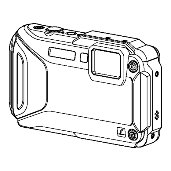
DMC-FT5EB
Model No.
DMC-FT5EE
DMC-FT5EF
DMC-FT5EG
DMC-FT5EP
DMC-FT5GC
DMC-FT5GA
DMC-FT5GN
DMC-FT5EA
DMC-TS5P
DMC-TS5PC
DMC-TS5PU
DMC-TS5GH
DMC-TS5GT
DMC-TS5GD
Colours
(A)....................Blue Type (Except DMC-FT5EE/EA,
DMC-TS5GH/GT/GD)
(D)....................Orange Type
(S)....................Silver Type (Except DMC-FT5EF/EA,
DMC-TS5PC/PU)
(K)....................Black Type (Except DMC-FT5EE/GN/EA,
DMC-TS5PC/GH/GT/GD)
© Panasonic Corporation 2013.
Unauthorized copying and distribution is a violation
of law.
ORDER NO.DSC1304010CE
B26
Digital Camera
Advertisement
Table of Contents


Need help?
Do you have a question about the DMC-FT5EB and is the answer not in the manual?
Questions and answers