
Related Manuals for Hitachi G 13SR


Summary of Contents for Hitachi G 13SR
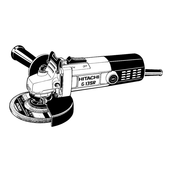
- Page 1 MODEL G 13SR POWER TOOLS TECHNICAL DATA DISC GRINDER G 13SR SERVICE MANUAL LIST No. E238 May. 2000 SPECIFICATIONS AND PARTS ARE SUBJECT TO CHANGE FOR IMPROVEMENT...
-
Page 2: Table Of Contents
Notice for use Specifications and parts are subject to change for improvement. Refer to the Hitachi Power Tool Technical News for further information. CONTENTS Page [ Business Section ] 1. PRODUCT NAME • • • • • • • • • • • • • • • • • • • • • • • • • • • • • • • • • • • • • • • • • • • • • • • • • • • • • • • • • • • • • • • • • • • • • • • • • • • • • • • • • • • • • • • • • • • • • • • • • • • • • • • • • • • • • • • • • • • • • • • •... -
Page 3: Product Name
The performance and other features of Model G 13SR are basically the same as for Model G 12SR, except for the wheel size and gear ratio. -
Page 4: Specifications
5. SPECIFICATIONS Model G 13SR Item O.D. 125 mm (5") x Thickness 6 mm (1/4") Dimensions x I.D. 22 mm (7/8") Depressed Offset amount : 4.8 mm (3/16") center wheel Max. practical 4,800 m/min. (15,800 ft/min., 80 m/s) peripheral speed... -
Page 5: Comparisons With Similar Products
6. COMPARISONS WITH SIMILAR PRODUCTS 6-1. Specification Comparisons Maker HITACHI Model G 13SR G 10SR/G 12SR Wheel diameter 125 (5") 100/115 (4"/4-1/2") 125 (5") Power input Power output Max. power output /min. No-load speed 10,000 11,000 10,000 56 (2-7/32") 63 (2-15/32") -
Page 6: Comparisons In Torque Vs. Rotation Speed And Stator Coil Temperature Rise
2 The rotation speed of HITACHI G 13SR at the same torque is high and the stator coil temperature is low. As the speed and the temperature are well balanced, HITACHI G 13SR ensures excellent performance for different jobs regardless of the magnitude of load. -
Page 7: Precautions In Sales Promotion
7. PRECAUTIONS IN SALES PROMOTION In the interest of promoting the safest and most efficient use of the Model G 13SR Disc Grinder by all of our customers, it is very important that at the time of sale, the salesperson carefully ensures that the buyer seriously recognizes the importance of the contents of the Handling Instructions, and fully understands the meaning of the precautions listed on the Name Plate or Caution Plate attached to each tool. -
Page 8: Precautions On Usage
7-3. Precautions on Usage (1) The wheel guard must be aligned in relation to the side handle mounting position. As illustrated in Figs. 2 and 3 the customer should be instructed that the wheel guard mounting angle must be aligned and fixed in accordance with the side handle mounting position so that the operator's hand will not contact the depressed center wheel. -
Page 9: Precautions In Disassembly And Reassembly
8. PRECAUTIONS IN DISASSEMBLY AND REASSEMBLY The [Bold] numbers in the descriptions below correspond to the numbers in the Parts Lists and exploded assembly diagrams for G 13SR. 8-1. Disassembly of the Armature (1) Loosen the Machine Screw (W/SP. Washer) M5 x 16 [26] and remove the Wheel Guard Ass'y [28]. -
Page 10: Precautions On Reassembly
8-4. Precautions on Reassembly 1) Thoroughly coat the grease (Hitachi Motor Grease N.P.C. SEP-3A, Code No. 930035, is recommended) on the gear teeth of the gear and pinion. Special attention must be given to ensure that the grease is applied properly all the way to the base of each gear teeth. -
Page 11: Wiring Diagram
8-7. Wiring Diagram (1) For China Switch Armature Cord Noise suppressor Choke coil Stator Fig. 6 (2) For other countries Switch Armature Cord Stator Fig. 7 8-8. Remaining Reassembly Remaining reassembly can be accomplished by following the disassembly procedures in reverse. 8-9. -
Page 12: Standard Repair Time (Unit) Schedules
9. STANDARD REPAIR TIME (UNIT) SCHEDULES Variable MODEL 60 min. Fixed Work Flow G 13SR Slide Switch Cord Housing Ass'y Tail Cover Stator Ass'y Slide Bar General Assembly Pinion Bearing Cover Ball Bearing (608 VVMC) Inner Cover Armature Ball Bearing... -
Page 13: Assembly Diagram For G 13Sr
Assembly Diagram for G 13SR --- 11 ---... - Page 14 G 13SR PARTS ITEM CODE NO. DESCRIPTION REMARKS USED 937-807 TAPPING SCREW D5X25 302-149 GUARD PLATE 301-944 PUSHING BUTTON 314-125 GEAR COVER ASS'Y INCLUD.3,16 301-941 SPECIAL NUT M7 301-939 PINION 314-430 SLOTTED HD. SCREW (SEAL LOCK) M4X10 608-VVM BALL BEARING 608VVC2PS2L...
- Page 15 G 13SR PARTS ITEM CODE NO. DESCRIPTION REMARKS USED 315-494 TAIL COVER 307-811 TAPPING SCREW (W/FLANGE) D4X16 (BLACK) 500-409Z CORD (CORD ARMOR D8.8) 960-266 CORD CLIP 308-094 CORD CLIP FOR CHN 981-373 TUBE (D) FOR CORD 4 --- 00 : ALTERNATIVE PARTS...
-
Page 16: Standard Accessories
G 13SR STANDARD ACCESSORIES ITEM CODE NO. DESCRIPTION REMARKS USED 938-332Z WRENCH 318-312 SIDE HANDLE OPTIONAL ACCESSORIES ITEM CODE NO. DESCRIPTION REMARKS USED 302-142 SIDE HANDLE 316-822 D. C. WHEELS 125MM A36Q (25 PCS.) 310-338 SUPER WASHER : ALTERNATIVE PARTS...
Need help?
Do you have a question about the G 13SR and is the answer not in the manual?
Questions and answers