Table of Contents
Advertisement
Advertisement
Table of Contents

Related Manuals for Mitsubishi Electric PEA-M200LA


Summary of Contents for Mitsubishi Electric PEA-M200LA
-
Page 2: Table Of Contents
CONTENTS I Safety Precaution [1] Safety Precaution ........................1 1.Always observe for safety....................... 1 2.Cautions related to new refrigerant..................1 II Part Names and Functions [1] Part Names and Functions ....................... 7 III Specification [1] Specification ........................... 15 IV Fan Performance and Corrected Air Flow [1] Fan Performance and Corrected Air Flow ................ - Page 3 HWE20020...
-
Page 4: I Safety Precaution
[ I Safety Precaution ] I Safety Precaution [1] Safety Precaution MEANINGS OF SYMBOLS DISPLAYED ON THE UNIT This mark is for R32 refrigerant only. Refrigerant type is written on nameplate of outdoor unit. WARNING In case that refrigerant type is R32, this unit uses a flammable refrigerant. (Risk of fire) If refrigerant leaks and comes in contact with fire or heating part, it will create harmful gas and there is risk of fire. - Page 5 [ I Safety Precaution ] [1] Warning for service (1) Do not alter the unit. (2) For installation and relocation work, follow the instructions in the Installation Manual and use tools and pipe components specifically made for use with refrigerant specified in the outdoor unit installation manual. (3) Ask a dealer or an authorized technician to install, relocate and repair the unit.
- Page 6 [ I Safety Precaution ] [4] Cautions for unit using R32 refrigerant Basic work procedures are the same as those for conventional units using refrigerant R410A. However, pay careful attention to the following points. (1) Information on servicing (1-1) Checks on the Area Prior to beginning work on systems containing flammable refrigerants, safety checks are necessary to ensure that the risk of ignition is minimized.
- Page 7 [ I Safety Precaution ] (3) Repair to intrinsically Safe Components Do not apply any permanent inductive or capacitance loads to the circuit without ensuring that this will not exceed the permissible voltage and current permitted for the equipment in use. Intrinsically safe components are the only types that can be worked on while live in the presence of a flammable atmos- phere.
- Page 8 [ I Safety Precaution ] b) Isolate system electrically. c) Before attempting the procedure, ensure that: · mechanical handling equipment is available, if required, for handling refrigerant cylinders; · all personal protective equipment is available and being used correctly; · the recovery process is supervised at all times by a competent person; ·...
- Page 9 [ I Safety Precaution ] Unit Electronic weighing scale [5] Service tools Use the below service tools as exclusive tools for R32/R410A refrigerant. Refer to the spec name plate on outdoor unit for the type of refrigerant being used. Tool name Specifications Gauge manifold ·...
-
Page 10: Part Names And Functions
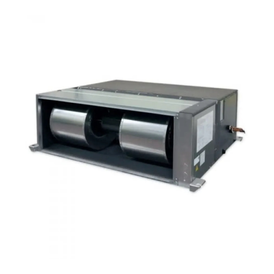
[ II Part Names and Functions ] II Part Names and Functions [1] Part Names and Functions Indoor Unit • Air outlet Air inlet In case of rear inlet - 7 - HWE20020... - Page 11 [ II Part Names and Functions ] Wired remote controller (option) Wired remote controller function * The functions which can be used are restricted according to the model. : Supported : Unsupported PAR-40MAA Function Slim City multi Body Product size H 14.5 l l u Backlight...
- Page 12 [ II Part Names and Functions ] The main display can be displayed in two different modes: "Full" and "Basic". The initial setting is "Full". To switch to the "Basic" mode, change the setting on the Main display setting. <Full mode> <Basic mode>...
- Page 13 [ II Part Names and Functions ] Menu structure Main menu Operation Vane•Louver•Vent. (Lossnay) High power Comfort Manual vane angle 3D i-See sensor Timer menu Timer On/Off timer Auto-Off timer Weekly timer OU silent mode Night setback Energy saving Restriction Temp.
- Page 14 [ II Part Names and Functions ] Maintenance menu Error information Filter information Cleaning Auto descending panel Descending operation Descending adjustment Service menu Test run menu Test run Drain pump test run Maintenance information Model name input Serial No. input Dealer information input Initialize maintenance info.
- Page 15 [ II Part Names and Functions ] Main menu list Main menu Setting items Setting details Operation Vane•Louver•Vent. Use to set the vane angle. (Lossnay) • Select a desired vane setting from five different settings. Use to turn ON/OFF the louver. •...
- Page 16 [ II Part Names and Functions ] Main menu Setting items Setting details Initial Basic Clock Use to set the current time. setting setting Daylight Sets the daylight saving time. saving time Display Main Use to switch between "Full" and "Basic" modes for the Status display and the setting display Main display.
- Page 17 [ II Part Names and Functions ] Wireless remote controller (option) Operation buttons CHECK TEST RUN SET TEMPERATURE button ON/OFF button MODEL SELECT SET TEMPERATURE button sets and Pushing button starts operation. any desired room temperature. Pushing again stops operation. NOT AVAILABLE TEMP ON/OFF...
-
Page 18: Specification
[ III Specification ] III Specification [1] Specification Service Ref. PEA-M200LA Cooling, Heating Mode Power supply Single phase, 50Hz, 220-240V Input 0.35 Running Current 2.13 External finish Galvanized sheets Heat exchanger Plate fin coil Fan (drive) × No. × No. -
Page 19: Fan Performance And Corrected Air Flow
[ IV Fan Performance and Corrected Air Flow ] IV Fan Performance and Corrected Air Flow [1] Fan Performance and Corrected Air Flow PEA-M200LA PEA-M200LA External static pressure: 60Pa External static pressure: 75Pa Power source: 220-240V 50Hz Power source: 220-240V 50Hz... - Page 20 [ IV Fan Performance and Corrected Air Flow ] PEA-M250LA PEA-M250LA External static pressure: 60Pa External static pressure: 75Pa Power source: 220-240V 50Hz Power source: 220-240V 50Hz High Limit High Limit Middle Middle Limit Limit Air flow rate [m /min] Air flow rate [m /min] PEA-M250LA...
-
Page 21: Sound Pressure Levels
[ V Sound Pressure Levels ] V Sound Pressure Levels [1] Sound Pressure Levels 1. Sound pressure level Ceiling concealed Aux. duct test unit Measurement location - 18 - HWE20020... -
Page 22: Nc Curves
[ V Sound Pressure Levels ] 2. NC curves PEA-M200LA (External static pressure 60Pa) (External static pressure 75Pa) 70.0 70.0 High High Middle Middle 65.0 65.0 60.0 60.0 55.0 55.0 NC-60 NC-60 50.0 50.0 45.0 45.0 NC-50 NC-50 40.0 40.0 35.0... - Page 23 [ V Sound Pressure Levels ] PEA-M250LA (External static pressure 60Pa) (External static pressure 75Pa) 70.0 70.0 High High Middle Middle 65.0 65.0 60.0 60.0 55.0 55.0 NC-60 NC-60 50.0 50.0 45.0 45.0 NC-50 NC-50 40.0 40.0 35.0 35.0 NC-40 NC-40 30.0 30.0...
-
Page 24: Outlines & Dimensions
[ VI Outlines & Dimensions ] VI Outlines & Dimensions [1] Outlines & Dimensions INDOOR UNIT Unit: mm PEA-M200, 250LA - 21 - HWE20020... - Page 25 [ VI Outlines & Dimensions ] Unit: mm - 22 - HWE20020...
-
Page 26: Wiring Diagram
[ VII Wiring Diagram ] VII Wiring Diagram [1] Wiring Diagram PEA-M200, 250LA - 23 - HWE20020... -
Page 27: Refrigerant System Diagram
[ VIII Refrigerant System Diagram ] VIII Refrigerant System Diagram [1] Refrigerant System Diagram PEA-M200, 250LA Heat exchanger Refrigerant GAS pipe connection (Brazed (PEA-M200, 250)) Thermistor TH5 (Cond./ Eva.temperature) Refrigerant flow in cooling Refrigerant flow in heating Refrigerant LIQUID pipe connection (Brazed (PEA-M200, 250)) Thermistor TH2 Thermistor TH1... -
Page 28: Troubleshooting
[ IX Troubleshooting ] IX Troubleshooting [1] Troubleshooting 1. Cautions on troubleshooting (1) Before troubleshooting, check the followings: 1 Check the power supply voltage. Check the indoor/outdoor connecting wire for mis-wiring. Connect the connectors of external input/output devices to the circuit board to which the remote controller is connected. - Page 29 [ IX Troubleshooting ] • For description of each check code, refer to the following table. Intake sensor error Pipe (TH2) sensor error Pipe (TH5) sensor error E6,E7 Indoor/outdoor unit communication error Each unit has two each of the Drain sensor error following: intake sensors, liquid Drain pump error pipe sensors, 2-phase pipe...
- Page 30 [ IX Troubleshooting ] [Output pattern A] Errors detected by indoor unit Wired remote Wireless remote controller controller Symptom Remark Beeper sounds/OPERATION INDICATOR lamp flashes Check code (Number of times) Intake sensor error Pipe (Liquid or 2-phase pipe) sensor error P2, P9 Indoor/outdoor unit communication error E6, E7...
- Page 31 [ IX Troubleshooting ] For description of each LED (LED1, 2, 3) provided on the indoor controller, refer to the following table. LED 1 (power for microcomputer) Indicates whether control power is supplied. Make sure that this LED is always lit. LED 2 (power for remote controller) Indicates whether power is supplied to the remote controller.
-
Page 32: Self-Diagnosis Action Table
[ IX Troubleshooting ] 3. Self-diagnosis action table Note: Refer to the manual of outdoor unit for the details of display such as F, U, and other E. Abnormal point and detection method Countermeasure Error Code Cause Room temperature Defective thermistor –... - Page 33 [ IX Troubleshooting ] Abnormal point and detection method Countermeasure Error Code Cause Freezing/overheating protection is (Cooling or drying mode) (Cooling or drying mode) working Clogged filter (reduced airflow) Check clogging of the filter. Freezing protection (Cooling mode) Short cycle of air path Remove shields.
- Page 34 [ IX Troubleshooting ] Abnormal point and detection method Countermeasure Error Code Cause Abnormality of pipe temperature ther- Defective thermistor – Check resistance value of thermistor. mistor/Condenser-Evaporator (TH5) characteristics For characteristics, refer to error code P1 The unit is in three-minute resume pro- above.
- Page 35 [ IX Troubleshooting ] Abnormal point and detection method Countermeasure Error Code Cause Indoor/outdoor unit communication * Check LED display on the outdoor control cir- Contact failure, short circuit or, error (Signal receiving error) cuit board. (Connect A-control service tool, mis-wiring (converse wiring) of Abnormal if indoor controller board PAC-SK52ST.)
-
Page 36: Test Point Diagram
[ IX Troubleshooting ] 4. Test point diagram Indoor controller board Emergency operation Model selection Capacity setting Function setting CN32 Remote start/stop adapter CN22 For MA remote controller cable con- nection (10 - 13 VDC (Between 1 and 3.)) CN41 CN51 Centralized control CN41 JAMA standard HA terminal A CN51... -
Page 37: Trouble Criterion Of Main Parts
[ IX Troubleshooting ] 5. Trouble criterion of main parts Part name Check method and criterion Room temperature Measure the resistance with a tester. thermistor (Part temperature 10°C ~ 30°C) (TH1) Normal Abnormal Pipe temperature 4.3kΩ~9.6kΩ Opened or short-circuited thermistor/liquid (TH2) Condenser/evaporator temperature thermistor... -
Page 38: Dc Fan Motor (Fan Motor/Indoor Controller Board)
[ IX Troubleshooting ] 7. DC fan motor (fan motor/indoor controller board) Check method of DC fan motor (fan motor/indoor controller circuit board) Notes · High voltage is applied to the connecter (CNMF) for the fan motor. Give attention to the service. ·... -
Page 39: Functions Of Dip Switch And Jumper Wire
Jumper wire Setting by the dip switch and jumper wire Remarks Functions For service board Model settings Service board MODELS PEA-M200LA Capacity settings PEA-M250LA Model settings <Settings at time of factory shipment> Wireless remote controller: 0 Control PCB setting Wireless remote... -
Page 40: Disassembly Procedure
[ X Disassembly Procedure ] X Disassembly Procedure [1] Disassembly Procedure 1. Control box Exercise caution when removing heavy parts. 1. Removing the control box cover (1) Remove the two fixing screws on the cover (A) to remove it. Fig. 1 2. -
Page 41: Thermistor (Condenser/Evaporator) (Liquid Pipe)
[ X Disassembly Procedure ] 3. Thermistor (Condenser/evaporator) (Liquid pipe) Exercise caution when removing heavy parts. 1. Remove the control box cover according to the procedure in section 1. 2. Removing the maintenance cover (1) Remove the nine fixing screws on the cover (D), cover (E), and cover (F) to remove the maintenance cover. -
Page 42: Heat Exchanger
[ X Disassembly Procedure ] 5. Heat exchanger Exercise caution when removing heavy parts. 1. Remove the control box cover according to the procedure in section 1. 2. Remove the maintenance cover according to the procedure in section 3. 2. 3. -
Page 43: Fan, Fan Motor And Fan Case
[ X Disassembly Procedure ] 6. Fan, fan motor and fan case Exercise caution when removing heavy parts. 1. Remove the control box cover according to the procedure in section 1. 2. Removing the fan motor (1) Disconnect the fan motor connector (CNMF) from the Indoor controller board. -
Page 44: Electrical Work
[ XI Electrical work ] XI Electrical work [1] Function settings 1. For wired remote controller Maintenance password is required. Press Setting on the Main window, and select “Service” to set the maintenance settings. When the Service menu is selected, a window will appear asking for the password. To enter the current maintenance password (4 numerical digits), move the cursor to the digit you want to change with the [F1] or [F2] button, and set each number (0 through 9) with the [F3] or [F4] button. - Page 45 [ XI Electrical work ] Use the [F1] or [F2] button to move the cursor to select the mode number, and change the setting number with the [F3] or [F4] button. When the settings are completed, press the [SELECT] button to send the setting data from the remote controller to the indoor units.
-
Page 46: Optional Parts
[ XII Optional parts ] XII Optional parts [1] Optional parts 1. Optional parts Drain pump PAC-KE06DM-F1 Filter Box PAC-KE250TB-F Long Life Filter PAC-KE85LAF - 43 - HWE20020... - Page 47 [ XII Optional parts ] - 44 - HWE20020...
Need help?
Do you have a question about the PEA-M200LA and is the answer not in the manual?
Questions and answers