Table of Contents
Advertisement
SETUP
SEQUENCE
Q 1
Q 2
A
B
C
A
B
C
MIN
MAX
MIN
MAX
ACTIVE
ACTIVE
Q-LINK
SEQUENCE
PAD 13
Q 3
Q 4
&
PAD
ASSIGN
MIN
MAX
MIN
MAX
PAD 9
ACTIVE
ACTIVE
#
FULL
LEVEL
Q 5
Q 6
PAD 5
16
LEVELS
!
ERASE
PAD 1
(
NOTE
ACTIVE
ACTIVE
REPEAT
)
Music production Center
CONTRAST
F 1
F 2
F 3
F 4
F 5
F 6
F 1
F 2
F 3
F 4
F 5
F 6
PAD BANK
NEXT
TRACK
D
E
F
SEQUENCE
MUTE
D
E
F
G
H
DRUMS
PAD 14
PAD 15
PAD 16
P LOOP
P TO
P FROM
PL AY
PAD 10
PAD 11
PAD 12
PAD 6
PAD 7
PAD 8
PAD 2
PAD 3
PAD 4
SERVICE MANUAL
REC GAIN
MAIN VOLUME
GAIN
HIGH
LOW
MIN
MAX
MIN
MAX
L
R
RECORD
SAMPLE
PROGRAM
I
J
K
7
8
9
MULTI
MIXER
EFFECT
L
M
N
4
5
6
SAVE
LOAD
GLOBAL
O
P
Q
1
2
3
SONG
MISC.
MIDI
R
S
T
0
ENTER
MAIN
SEQ EDIT
STEP EDIT
U
V
W
CURSOR
JOG
TIMING CORRECT
WINDOW
BLOCK
CURSOR
X
MASTER TEMPO
SHIFT
Y
LOCATE
UNDO SEQ
GO TO
STEP
BAR
Z
EVENT
START
END
PLAY/ REC
OVER
PLAY
TAP TEMPO
REC
STOP
PLAY
DUB
START
1
Advertisement
Table of Contents

Subscribe to Our Youtube Channel
Related Manuals for Akai MPC4000


Summary of Contents for Akai MPC4000
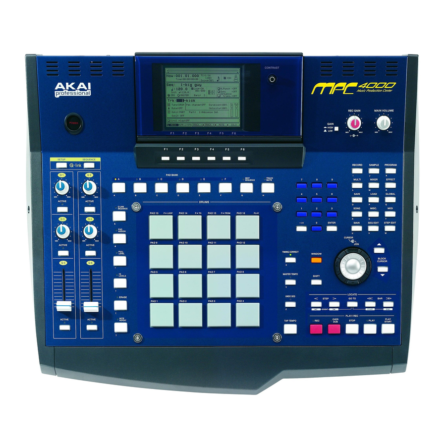
- Page 1 CONTRAST REC GAIN MAIN VOLUME GAIN HIGH SETUP SEQUENCE RECORD SAMPLE PROGRAM PAD BANK NEXT TRACK MULTI MIXER EFFECT SEQUENCE MUTE SAVE LOAD GLOBAL ACTIVE ACTIVE DRUMS Q-LINK SONG MISC. MIDI SEQUENCE PAD 13 PAD 14 PAD 15 PAD 16 P LOOP P TO P FROM...
-
Page 2: Safety Check After Servicing
# SAFETY INSTRUCTIONS # INFORMATIONS 1. Parts identified by the } symbol are critical for safety. SYMBOLS FOR PRIMARY DESTINATION Replace them only with the parts number specified. Unit destinations are indicated with letters as shown below. 2. In addition to safety, other parts and assemblies are Symbols Principal Destinations specified for conformance with such regulations as those... -
Page 3: Specifications
I. SPECIFICATIONS General Power supply 100-240V AC 50/60Hz 70W (27W without options) Dimensions 526 (W) x 170 (H) x 453 (D) mm (with LCD tilted down) Weight 10.5kg (without options) Display 320 x 240 dots grey-scale graphical LCD w/back light Sound Generator Sampling rate 44.1kHz, 48kHz, 96kHz... - Page 4 II. DISASSEMBLY In case of trouble, etc., necessitating dismantling, please dismantle in the order shown in the illustrations. Reassemble in the reverse order. 1. Removal of the OPERATION BLOCK ZS-322570 ST BID40X08STL NI3 ZS-331182 BT BID30X08STL BNI SERVICE MANUAL...
- Page 5 ZS-821548X SCREW TOP COVER NI ZS-331182 BT BID30X08 STL BNI ZS-331182 BT BID30X08 STL BNI SERVICE MANUAL...
- Page 6 ZS-331182 BT BID30X08 STL BNI SERVICE MANUAL...
-
Page 7: Principal Parts Location
III. PRINCIPAL PARTS LOCATION EM-812761J IND LCD BA-L4016A504C BA-L4016A504F PC LCD BLK PC POWER SW BLK BA-L4016A502C PC IO VR BLK BA-L4016A504B PC FUNCTION BLK BA-L4016A504A PC JOG BLK BA-L4016A030A PC OPERATION BLK BA-L4016A502A BA-L6052A020A PC IO BLK BA-L4016A502B PC CPU BLK Z8 BA-L4016A504E PC IO ADDA BLK PC FILTER BLK... - Page 8 The Driver software will be placed correctly and the MPC4000 is recognized properly. 2. OS update Double click on the OS Loader.exe icon and specify the OS .bin file. It will send the OS to the MPC4000. [Caution] After the update, be sure to initialize the MPC4000 by pressing the GLOBAL key, and then [F6] (INITIAL) and [F5] (DO IT) keys, before turning it off.
-
Page 9: Test Mode
CPU Board Test Mode The Test Mode of the MPC4000 CPU Board is performed while the CPU board is mounted on the Z4/Z8 Sampler. When the Z4/Z8 is switched on after the MPC4000 CPU Board is mounted on the Z4/Z8 Sampler, the sampler is turned on with the MPC4000 screen. -
Page 10: How To Use This Parts List
VI. PARTS LIST ATTENTION 1. When placing an order for parts, be sure to list the Part No., Model No. and the description of each part. Otherwise, the non-delivery of the part or the delivery of a wrong part may result. 2. - Page 11 OSC X'TAL C.DS0751SB 40.0000MHZ Ref.No. Part No. Description EI-820989X OSC X'TAL C.DS0751SV 48.0000MHZ BA-L6052A020A PC CPU BLK Z8 BA-L4016A020A PC (#) IO BLK MPC4000 BA-L4016A030A PC OPERATION BLK MPC4000 3. P.C. IO BLOCK BA-L4016A040A PC (#) OTHER BLK MPC4000 Ref.No. Part No. Description...
- Page 12 Ref.No. Part No. Description Ref.No. Part No. Description ER-812771J R OMF V T05FS ERX12SE1/2W 1R0J EJ-821386X PHONE J YKB22-5264 NUT 6.3 ER-821483X R OMF H S15 FS ERG2SH 2W 820J R361 ER-422512J R OMF H S15 FS ERG2SH 2W 151J ET-429896J TR C.DTA144EKA T146T08E EQ-348929...
- Page 13 Ref.No. Part No. Description Ref.No. Part No. Description D135 ED-811455J D SILICON H 1SS133T-77 T26 D305 ED-811455J D SILICON H 1SS133T-77 T26 D136 ED-811455J D SILICON H 1SS133T-77 T26 D310 ED-811455J D SILICON H 1SS133T-77 T26 D137 ED-811455J D SILICON H 1SS133T-77 T26 D311 ED-811455J D SILICON H 1SS133T-77 T26...
- Page 14 Ref.No. Part No. Description Ref.No. Part No. Description SW135 ES-349474 SW TACT SKHHAM004A D175 ED-811455J D SILICON H 1SS133T-77 T26 SW136 ES-349474 SW TACT SKHHAM004A D176 ED-811455J D SILICON H 1SS133T-77 T26 SW137 ES-349474 SW TACT SKHHAM004A SW171 ES-349474 SW TACT SKHHAM004A SW138 ES-349474 SW TACT SKHHAM004A...
- Page 15 Ref.No. Part No. Description Ref.No. Part No. Description EI-820992X OSC X'TAL C.DS0751SV 25.0000MHZ IC11 EI-810591J IC NJM5532L IC12 EI-821226X IC OPA2134UA FPT12E IC13 EI-810591J IC NJM5532L 9. IB-4D IC14 EI-821442X IC PCM1730E FPT16E IC15 EI-821226X IC OPA2134UA FPT12E Ref.No. Part No. Description IC16 EI-810591J...
- Page 16 Ref.No. Part No. Description Ref.No. Part No. Description 12 SW ES-415015J SW TACT SKQEAD ES-428287J SW SLIDE SSSF112-S06N1 1-02N BUTTON PUSH B(5) [ White ] [ Termineter ] 13 BUTTON SB-821550X 13 SW ES-415015J SW TACT SKQEAD EJ-820754X PIN J YKC21-3079 P2P [ TAP TEMPO ONLY ] [ DIGITAL I/O ] 13 SW...
-
Page 17: Final Assembly Block
FINAL ASSEMBLY BLOCK 68 17 16 18 CONTRAST REC GAIN MAIN VOLUME GAIN HIGH SETUP SEQUENCE RECORD SAMPLE PROGRAM PAD BANK NEXT TRACK MULTI MIXER EFFECT SEQUENCE MUTE SAVE LOAD GLOBAL ACTIVE ACTIVE DRUMS Q-LINK SONG MISC. MIDI SEQUENCE PAD 13 PAD 14 PAD 15 PAD 16... - Page 18 FINAL ASSEMBLY BLOCK 41 51 ZS-418538J ZS-417137 SERVICE MANUAL...
-
Page 19: Lcd Block
LCD BLOCK SERVICE MANUAL... -
Page 20: Information Of Ics
VII. INFORMATION OF ICs 1. IC Explanation. 1-1 IC1 SA1110B (Intel CPU) 206MHz version chip. CPU clock : 176.9MHz. SDRAM (CPU work memory) : 88.45MHz (=176.9MHz/2) 1-1-2 Pin Descriptions Signal name Explanation D[31:0] Data-bus A[25:0] Address-bus SDCKE1 SDRAM clock enable for CPU’s work memory SDCLK1 SDRAM clock for CPU’s work memory.(88.45MHz) SDCLK2... - Page 21 Signal name Explanation TxD_C CD digital recognition. Low=connected.(MPC only) SCLK_C BM1. Machine recognition. Low=Z4/8. High=MPC. SFRM_C BM0. Connected GND now. for future. LDD[7:0] LCD controller display data. L_BIAS LCD ac bias drive. L_PCLK LCD pixel clock. L_LCLK LCD line clock. L_FCLK LCD frame clock.
- Page 22 1-6. IC8 XC95144XL-7TQ100C (Complex programable logic (CPLD). Address decoder. Expansion port by using data-latch. Communication logic for RTC. Selector. 1-6-2. Pin Descriptions Signal name Explanation D[7:0] Connected with CPU data bus for communication. A[24:21] Connected with CPU address bus for communication. /CS[5:0] Chip select for other device.
- Page 23 Signal name Explanation /FP2_PROG For configuration to FPGA on ADAT PCB. PLD2_TMS For configuration to CPLD on DIO. PLD2_TDI PLD2_TDO For configuration to CPLD on DIO. TCK,TMS,TDI For configuration.(TCK is also used for CPLD on DIO) For configuration. VCCINT Positive supply for internal logic. +3.3V VccIO Positive supply for output driver.
- Page 24 1-8. IC10 SL811HST ( USB Host/Slave Controllers). 1-8-2. Pin Descriptions Pin No. Signal name Explanation Write Strobe. Active low. Chip select. Active low. Clock mode. H: at 12MHz. L: at 48MHz clock source. USBVDD Power for USB Transceivers. DATA+ USB Differential Data Signal High Side. DATA- USB Differential Data Signal Low Side.
- Page 25 1-9. IC11 FAS236U (SCSI Controller) 1-9-2. Pin Descriptions Pin No. Signal name Explanation DREQ DMA request. H: ready to transfer data. /DACK DMA acknowledge. /DBWR Data-bus write control. Indicates that chip is acting in initiator mode. DIFFSENS H: differential mode. Indicates that chip is acting in target mode.
- Page 26 1-10 IC12, 16 ALVCH16245 (16 bit Bus bidirectional transceivers) 1-11 IC13-15 ALVCH16244 (16 bit Bus Buffers) 1-12 IC17, 18 LVC244 (8 bit Bus Buffers) 1-13 IC19 LVC245 (8 bit Bus bidirectional transceivers) In particular, this is used for changing 5V into 3.3V. 1-14 IC20 M51957B (System Reset IC.
-
Page 27: Appendix: Installing Storage Devices (For Service Engineers)
This appendix explains how to install storage devices (ATA hard disk, CD-ROM drive, Zip drive, etc.) in the MPC4000. Check the included items The following items are included with the MPC4000 for use when installing storage devices. Check to make sure that no items are missing. - Page 28 3. Remove the screw (located in the center of the front panel) that fastens the top panel from the lower front side. 4. Remove the screw (located in the center of rear panel) that fastens the top panel from the rear side. 5.
-
Page 29: Installing A Drive
2. Use the hard disk attachment screws (included with the MPC4000) to attach the drive to the bracket, and attach the bracket to the bottom panel of the chassis. Use the bracket in the correct direction (as illustrated or on reverse side) according to the drive mounted. -
Page 30: Cable Connections
When installing a drive in the 5 inch bay Bracket (L) PC IO PC IO AD_DA PC CPU Cable connections Connecting the flat cable 1. Remove two screws from the cover that conceals the PC CPU board. When you remove the cover, you will see the P2 connector for the ATA drive. Bracket (S) PC IO AD_DA Step 1... -
Page 31: Connecting The Power Cable
3. On the PC I/O ADDA board, plug in the P22 jumper (located in front of P23) at the “SET” position. Connecting the CD-ROM digital audio cable If the IB-4D digital I/O option is installed in the MPC4000, connect the digital audio output connector of the CD-ROM drive to the IB-4D as follows. - Page 32 Installation - MPC4000 1. Remove the fixing screws of the MPC4000 Side Panels (4pcs. on each side) and remove Side Panels. Next, remove the screws (5pcs. on each side) hidden by the Side Panels and then remov e the center screws (2pcs.) located underneath the Armrest and the topmost of Rear Panel.
- Page 33 Installation - MPC4000 1. Remove the fixing screws of the MPC4000 Side Panels (4pcs. on each side) and remove Side Panels. Next, remove the screws (5pcs. on each side) hidden by the Side Panels and then remove the center screws (2pcs.) located underneath the Armrest and the to pmost of Rear Panel.
- Page 34 – MPC4000 1. Remove the fixing screws of the MPC4000 Side Panels (4pcs. on each side) and remove Side Panels. Next, remove the screws (5pcs. on each side) hidden by the Side Panels and then remove the center screws (2pcs.) located underneath the Armrest and the topmost of Rear Panel.
- Page 35 1-3, Hiranuma 1-Chome, Nishi-Ku, Yokohama, Japan SERVICE SECT. PHONE : +81-45-412-2373 FAX : +81-45-412-2372 SERVICE MANUAL...
- Page 39 EMIFIL FL350 EMIFIL FL351 EMIFIL FL352 EMIFIL FL353 EMIFIL FL354...
Need help?
Do you have a question about the MPC4000 and is the answer not in the manual?
Questions and answers