
Related Manuals for Akai MPC4000


Summary of Contents for Akai MPC4000
- Page 1 User Guide WARNING To prevent fire or shock hazard, do not expose this appliance to rain or moisture.
- Page 2 Important Notice The material in this document is copyright to AKAI professional M.I. Corp., and may not be quoted or reproduced in any form without written permission from the company. LIMITED SOFTWARE WARRANTY POLICY All the software provided with, or purchased especially for, AKAI professional products has been tested for functionality.
- Page 3 The Z4/Z8 is designed to be used in a standard household environment. Power requirements for electrical equipment vary from area to area. Please ensure that your Z4/Z8 meets the power requirements in your area. If in doubt, consult a qualified electrician or AKAI profes- sional dealer.
- Page 4 For U.K. customers only WARNING THIS APPARATUS MUST BE EARTHED IMPORTANT This equipment is fitted with an approved non-rewireable UK mains plug. To change the fuse in this type of plug proceed as follows: 1) Remove the fuse cover and old fuse. 2) Fit a new fuse which should be a BS1362 5 Amp A.S.T.A or BSI approved type.
- Page 5 32-En COPYRIGHT NOTICE The AKAI professional Z4/Z8 is a computer-based device, and as such contains and uses soft- ware in ROMs. This software, and all related documentation, including this Operator’s Manual, contain proprietary information which is protected by copyright laws. All rights are reserved. No part of the software or its documentation may be copied, transferred or modified.
-
Page 6: Table Of Contents
2 Introducing the MPC4000 ......8 How the MPC4000 is structured ......8 Sampler section . - Page 7 Contents Editing a sequence ........36 Copying a sequence .
- Page 8 10 Using storage devices ......95 The file structure of the MPC4000 ......95 File operations for a storage device .
-
Page 9: Parts And Their Functions
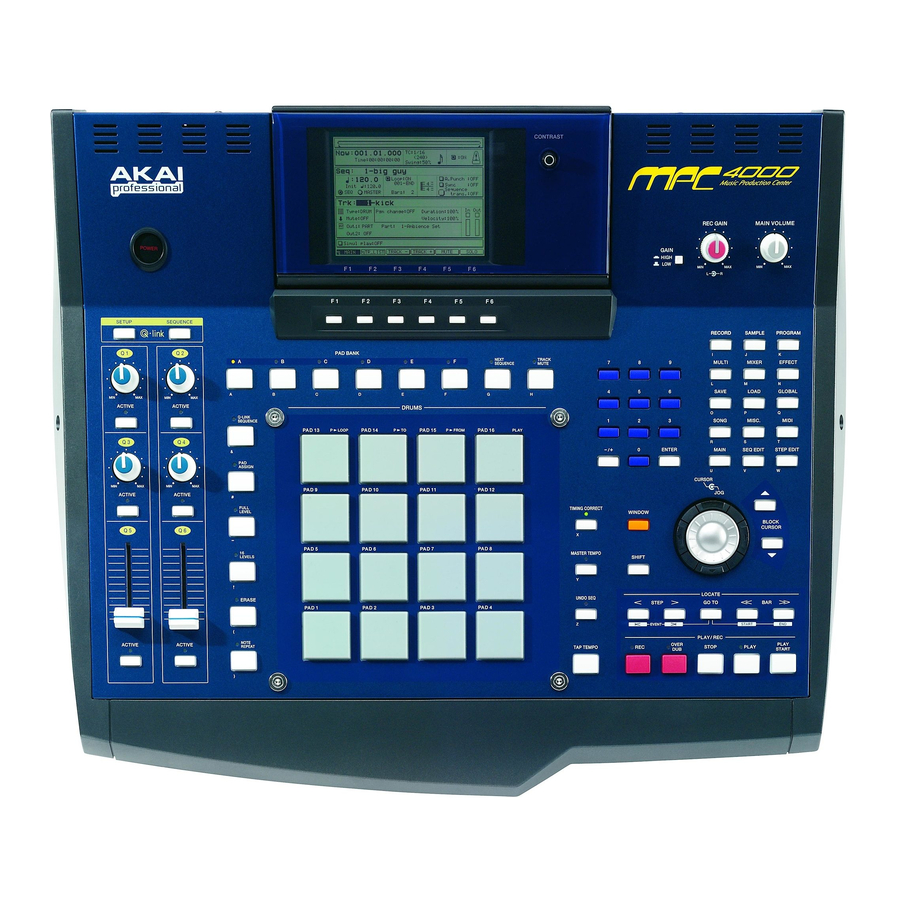
Parts and their functions 1 Parts and their functions This chapter describes the parts of the MPC4000 and their functions, and explains how to make connections. Parts and their functions This chapter explains the names and functions of each part of the MPC4000. -
Page 10: Q-Link Section
In this section you can operate the velocity-sensitive pads, and make various settings for them. Pads 1–16: These are velocity sensitive pads used to play the MPC4000’s sampler section and external MIDI devices. In some pages, these pads are used to select tracks or sequences. -
Page 11: Data Entry Section
[–/+] keys: These keys switch the sign (negative/positive) of the value that was input by the numeric keys. Mode section In this section you can switch between the various modes of MPC4000. Each key corresponds to the following mode. [RECORD] key: Record mode... -
Page 12: Rear Panel
Chapter 1—Parts and their functions [TAP TEMPO] key: This key is used to manually specify the tempo. Striking this key repeatedly will automatically set the tempo to the corresponding quarter-note interval. [WINDOW] key: This key opens a window for making detailed settings. When you move the cursor to a specific field in the display and press this key, a window for that field will open. -
Page 13: Front Panel
For compatible devices, contact your Akai dealer or Akai Professional M.I Service Department. Note: If a removable disk drive is installed in the MPC4000, protect the disk by taking it out of the drive when you are not actually loading or saving data on it. -
Page 14: Audio/Midi Connections
Chapter 1—Parts and their functions Audio/MIDI connections When connecting external audio or MIDI devices to the MPC4000, make connections as shown in the dia- gram below. CD player Monitor speakers LINE OUT Mixer Turntable LINE OUT R Foot switches INPUT INPUT... -
Page 15: Connecting Scsi Devices
• Set the ID numbers of the SCSI devices so that they do not conflict with each other. • At the factory, the MPC4000 is set to a SCSI ID of 6. However, you may change this if necessary. For details, refer to the PDF reference manual. -
Page 16: Introducing The Mpc4000
Chapter 2—Introducing the MPC4000 2 Introducing the MPC4000 This chapter describes how the MPC4000 is structured, and explains the special terms you will need to know when using it. This chapter also explains the user interface of the MPC4000, and basic operating procedures. - Page 17 Sampler section The following diagram is an example of a drum program in which one sample is assigned to each pad. PA D 13 LOOP PA D 14 PA D 15 FROM PA D 16 PL AY Note number: 53 Zone1: RIDE PA D 9 PA D 10...
-
Page 18: Sequencer Section
Within a multi, a “part” refers to each of the areas for which you make individual settings for a program. One multi lets you use up to 128 parts. To play the MPC4000’s programs, you assign programs to parts within the multi, and specify the level, out- put destination, pan, and effect send level etc. for each part. -
Page 19: Pad Section
Here’s how to perform the basic operations that are common to each screen of the MPC4000. Switching modes In order to perform an operation on the MPC4000, you must first use the keys of the mode section ( p.3) to access the desired mode. -
Page 20: Accessing A Page
field for that item, and press the [WINDOW] key. As an example, here’s how to access the clock function that is built into the MPC4000. 1. Press the [GLOBAL] key, and then press the [F1] key (GLOBAL). -
Page 21: Editing A Name
• Using the STEP [<][>] keys/BAR [< <]/[> >] keys/[GO TO] keys If the MPC4000 is in a state in which you can play back a sequence or song, you can use the STEP [<]/[>] keys, BAR [< <]/[> >] keys, and [GO TO] key to move the current location forward or backward. Each key has the following operation. -
Page 22: Playing A Program
• Using the Locate popup window If the MPC4000 is in a state in which you can play back a sequence, you can press the [GO TO] key to access a popup window where you can perform locate operations. IN this window you can memorize the current location as a locate point, or specify a locate point in measures/beats/ticks. - Page 23 Editing a value 5. Press the [F5] key (SELECT). The contents of the storage device will be displayed as a tree in the file list block in the upper part of the screen. 6. Move the cursor to the View field in the center of the display, and use the [JOG] dial to select “PROGRAM.”...
- Page 24 9. Make sure that the Load field is set to WITH SAMPLES, and press the [F5] key (DO IT button). The MPC4000 will load the program. If the Load field is set to WITH SAMPLES, the necessary samples will be loaded into memory along with the program.
-
Page 25: Creating And Editing A Sequence
This chapter explains how to record MIDI events into a sequence, and how to edit the recorded MIDI events. About sequences A “sequence” is the smallest unit from which an MPC4000 song is made up. You can specify the length (1–999 measures), tempo, and time signature of each sequence. On the MPC4000, you can create a song that consists of only one sequence, or you can create separate sequences and then arrange them later into a complete song. -
Page 26: Preparations For Creating A Sequence
Chapter 3—Creating and editing a sequence Preparations for creating a sequence Before you can record MIDI events in a track, you must specify certain parameters such as the number of measures, the time signature, and the tempo. 1. Press the [MAIN] key. The main page will appear. -
Page 27: Realtime Input
Realtime input The Change Bars popup window will appear. In this window you can specify the number of measures in the sequence. 4. Turn the [JOG] dial to specify the number of measures, and then press the [F6] key (DO IT) to finalize the setting. - Page 28 1. If you want to use a drum program of the internal sampler as your sound source, load the desired program into the internal memory of the MPC4000. 2. If you want to use an external rhythm machine as your sound source, connect one of the [MIDI OUT A]–[MIDI OUT D] connectors to the MIDI IN connector of your MIDI sound source.
- Page 29 Realtime input 5. Make sure that the Type field is set to DRUM. Hint: You can change this setting later as necessary. 6. Move the cursor to the Out1 field, and turn the [JOG] dial to select one of the following output destinations for the track.
-
Page 30: Realtime-Recording A Key Group Program
MPC4000 ( p.6). 3. If you want to use an external MIDI keyboard as the controller instead of the pads of the MPC4000, connect the MIDI OUT of your keyboard to the MPC4000’s [MIDI IN I] connector or [MIDI IN II] connector. - Page 31 Realtime input 7. Move the cursor to the Out1 field, and turn the [JOG] dial to select the output destination for the track. 8. Move the cursor to the PART or Ch field, and turn the [JOG] dial to select the part number or MIDI channel.
-
Page 32: Auto Punch-In/Out
Chapter 3—Creating and editing a sequence 15. To hear the content that you recorded, press the [PLAY] key (or the [PLAY START] key). 16. To erase a note event that you input by mistake, hold down the [OVER DUB] key and press the [PLAY] key. -
Page 33: Step Recording
Realtime input 5. In the same way, move the cursor to the Out time field, and turn the [JOG] dial to set the punch-out point. The punch-out point is shown as a symbol on the position bar of the main page. 6. - Page 34 Chapter 3—Creating and editing a sequence 5. Move the cursor to the Auto Step increment on key release field, and turn the [JOG] dial to make the field show YES. 6. Move the cursor to the Duration of recorded notes field, and turn the [JOG] dial to make the field show VALUE.
-
Page 35: Editing A Track
The following pages explain how to edit the note events and continuously-variable events recorded in a track. Using the Graphic Editor to edit On the MPC4000 you can use a graphic display to visually edit note events and continuously-variable events such as control changes. Here’s how to use the graphic display to edit MIDI events. -
Page 36: About The Editing Commands
Chapter 3—Creating and editing a sequence • To select a single grid location Press the pad that corresponds to the note event you want to edit. The horizontal marker will move to the location for that pad. • To select multiple grid locations Press the pad that corresponds to the note event you want to edit, and hold down the [SHIFT] key and use the CURSOR ]/[ √... - Page 37 Editing a track Move field: Indicates the direction in which the data will be moved. If this field is set to Time, the data can be moved along the time axis. If set to Note, the notes can be moved upward or downward. If the track is a drum-type track, this field can be set only to Time.
- Page 38 Paste Data popup window will appear when you press the key. Phrase Library field: This displays a list of the phrase libraries that have been stored in the MPC4000’s flash ROM. Paste event field: Here you can choose the type of MIDI events that will be pasted. If you choose NOTE, only the note data included in the library will be pasted.
- Page 39 Editing a track Editing an INST type track You can use a piano-roll graphic editor to perform editing operations such as Copy or Delete on the note events recorded in an INST type track. 1. Select an INST type track in the main page, and press the [SEQ EDIT] key. When you select an INST type track and press the [SEQ EDIT] key, the piano-roll graphic editor will appear.
- Page 40 Chapter 3—Creating and editing a sequence • To select multiple notes Press the pad or MIDI key for one of the note events you want to edit. Then hold down the [SHIFT] key and use the CURSOR [ ]/[ √ ]/[ ® ] keys to extend the selected range. π...
- Page 41 Editing a track 4. Move the cursor to the Timing correct field, and turn the [JOG] dial to specify the resolution of the time ruler. 5. Move the cursor to the Now field, and move the marker to the beginning of the area that you want to edit.
-
Page 42: Using The Event List
Chapter 3—Creating and editing a sequence 13. If desired, move the cursor to the Interval field and turn the [JOG] dial to specify the spacing at which the continuously-variable events will be added. You can set this field in a range of 1/4 (quarter note)–1 tick (1/960th of a quarter note). As you decrease the value of this setting, the continuously-variable events will change more smoothly. -
Page 43: Copying A Track
Editing a track MIDI event type/continuously-variable event value (for other events) • System exclusive Each byte of the message (hexadecimal) 5. Turn the [JOG] dial to edit the value of the MIDI event. When editing a system exclusive, use the CURSOR [ ® ] key to move to each byte. 6. -
Page 44: Deleting A Track
Copying a sequence Here’s how to copy a sequence in the memory of the MPC4000 to an empty sequence. 1. Access the main window, and move the cursor to the Seq field. 2. Press the [WINDOW] key. -
Page 45: Deleting A Sequence
1. Access the main page and select the sequence whose parameters you want to view. 2. Press the [F2] key (TR LIST). The first time you press the [F2] key after starting up the MPC4000, the Out1 page will appear, listing the Out1 field settings for each track. -
Page 46: Saving And Loading A Sequence
Saving all sequences/songs Here’s how to save all sequences/songs from the internal memory of the MPC4000 to a storage device. This method lets you back up all data of the sequencer section as a single file (an ALL file). - Page 47 Saving and loading a sequence Disk information: Indicates the storage device that is currently selected for the opera- tion. Type field: Selects the type of data that will be saved. Disk field: Selects the destination storage device. Save to field: Indicates the folder within the destination storage device.
-
Page 48: Saving A Single Sequence
file list block of the Load page. Saving a single sequence Here’s how to save a single sequence from the memory of the MPC4000 to a storage device. 1. Press the [SAVE] key. The Save page will appear. - Page 49 Press the [F6] key (DO IT) to access the Load ALL (songs and sequences) File popup window. When you load an ALL file, all sequence and song data in the memory of the MPC4000 will be overwritten. If internal memory contains data that you want to keep, save it to a storage device beforehand.
- Page 50 Chapter 3—Creating and editing a sequence • Move the cursor to the Seq field, and turn the [JOG] dial to select the desired sequence that you want to load from within the ALL file. • Move the cursor to the sequence list, and select the sequence number into which the sequence will be loaded.
-
Page 51: Creating And Editing A Song
In the same way as sequences, songs are kept in the internal memory of the MPC4000. If you turn off the power, all songs in memory will be lost. If you want to keep a song you created, you must save all sequences and songs from memory to an external storage device. -
Page 52: Editing A Song
Chapter 4—Creating and editing a song When you modify the contents of a song, a song name of “Song_xxx” (x will be a song number 001–128) will be assigned automatically. 5. If you want the sequence you assigned in step 4 to be repeated, move the cursor to the Repeat field and turn the [JOG] dial to specify the number of repeats. - Page 53 Editing a song If you copy or delete a step, the step you select here will be the step that is copied or deleted. If you insert or paste a step, the step will be inserted or pasted at the location of the step you select here. Hint: You can hold down the [SHIFT] key and use the CURSOR [ π...
-
Page 54: Deleting A Song
Chapter 4—Creating and editing a song Deleting a song Here’s how to delete a song from internal memory, returning it to an empty state. 1. Press the [SONG] key. The Song page will appear. 2. Move the cursor to the Song field, and turn the [JOG] dial to select the song that you want to delete. - Page 55 Converting a song into a sequence The Convert Song to Seq popup window will appear. This popup window lets you convert a song into a sequence. From song field: Selects the song that will be converted. To sequence field: Selects the destination for the converted sequence.
-
Page 56: Using Multis And Parts
Part. You can think of a “part” as being the settings that a program need in order to play back; e.g., volume, pan, and output jack assignments. On the MPC4000 you can use up to 128 parts. You can select a program and set parameters for each part, and use a sequencer or MIDI controller to play multiple parts simultaneously. -
Page 57: Editing Part Parameters
MIDI port and MIDI channel. Assigning a program to a part Here’s how you can assign a program from the MPC4000’s internal memory to each part of the currently selected multi. 1. Press the [MULTI] key, and then press the [F2] key (MIX). -
Page 58: Setting The Receive Midi Port/Midi Channel Of A Part
HIGH NOR- LOW. If the MPC4000 runs out of voices, it will turn off currently-sounding notes in the priority order you specify here. If you set a part to HOLD, its program will never be turned off. Adjusting the note range of a part By specifying the highest and lowest note that a part will play, you can limit a part to sounding only in a specific range of notes. -
Page 59: Adding Or Deleting A Part
Adding or deleting a part Multi field: Indicates the name of the cur- 1 3 45 rently selected multi. Part field: Indicates the part numbers. Program/Type field: Selects the program that will be assigned to the part. The Type field shows an abbreviation to indicate the program type. - Page 60 Hint: An asterisk * will be added before the name of multis whose contents you modified after saving or loading them. You can also switch multis by sending program changes to the MPC4000. (For details, refer to the PDF reference manual.) 2.
-
Page 61: Copying A Multi
Copying a multi Copying a multi Here’s how to copy a multi within the internal memory of the MPC4000. 1. Press the [MULTI] key. The list page will appear. 2. Move the cursor to the multi list, and press the [WINDOW] key. -
Page 62: Saving Or Loading A Multi
2. Move the cursor to the Type field, and turn the [JOG] dial to select SAVE MULTIs. When you select SAVE MULTIs, the following parts of the display will change. Data list: Shows the data in the MPC4000’s internal memory. -
Page 63: Loading A Multi
Wave free field: Displays the available amount of sample memory in the MPC4000. Sequence free field: Displays the available amount of memory in the sequencer section of the MPC4000. CPU free field: Displays the available amount of data management memory in the MPC4000. - Page 64 Chapter 5—Using multis and parts 2. Move the cursor to the Disk field, and turn the [JOG] dial to display the Disk List popup window. 3. Move the cursor to the storage device from which you want to load data, and press the [F5] key (SELECT).
-
Page 65: Mixer Mode Operations
Mixer mode operations 6 Mixer mode operations This chapter explains how to use Mixer mode to adjust the mix parameters of the parts. About Mixer mode In Mixer mode you can use the part mixer to adjust the mix parameters of each part. The Part Mixer lets you adjust the volume, pan, and effect bus send level for each part within the currently selected multi. - Page 66 Chapter 6—Mixer mode operations 4. Use the [Q1]/[Q3] knobs and [Q5] slider of the Q-LINK section to adjust the mix parameters of the currently selected part. While the Part page is displayed, you can use the [Q1] knob, [Q3] knob, and [Q5] slider to adjust the Fx field, Pan field, and Level field of the currently selected part.
-
Page 67: Effects
7 Effects The MPC4000 contains four effect units (effects 1–4) that you can use to process the programs of the sam- pler section. For each effect unit, you can select one of 52 effect types, and edit the effect parameters to obtain a wide range of effects. - Page 68 3. Turn the [JOG] dial to select the effect type. The MPC4000 provides the following effect types. For the effect produced by each type and details of the parameters, refer to the reference manual. Effect types Effect types CHORUS>MONO...
- Page 69 Basic effect operations Level field: Adjusts the signal level that is output from each effect. Direct signal field: Selects whether the sig- nal (unprocessed sound) from the parts that select the corresponding FX bus will be sent to the output jacks. If this is on, the signal from the part(s) and the signal processed by the effect will be mixed immediately before the output jacks.
-
Page 70: Editing The Effect Parameters
Chapter 7—Effects 10. Repeat steps 1–6 to make settings for other effects in the same way. 11. Press the [MULTI] key, and then press the [F2] key (MIX). The Mix page will appear. In this page you can adjust the mix parameters of the parts that are included in the currently selected multi. -
Page 71: Recording And Editing Samples
Drum program All of the samples that can be played on the MPC4000 are held in memory. When you turn off the power of the MPC4000, all samples in memory and their settings will be lost. If you want to keep the samples, you must save the samples (in some cases, the samples and programs) to a storage device before you turn off the power. -
Page 72: Recording (Sampling) An External Source
Hint: In order to play a sample that you record, you must assign the sample to a program. In this example, we will show how to assign the sample to the program that is created in memory when you turn on the power of the MPC4000. Preparations before recording 1. - Page 73 Recording (sampling) an external source Stop recording Start recording level Rec start threshold parameter time Time parameter Stop recording Start recording level Rec start threshold parameter • If you want to start recording manually Set the Record Start field to MANUAL. With this setting, recording will begin when you press the appro- priate key.
-
Page 74: Actual Recording
Chapter 8—Recording and editing samples 9. Set the Pre-recording time field and the Bit field as necessary, and press the [WINDOW] key or the [F1] key (CLOSE) to return to the previous screen. For example if you have selected THRESHOLD as the Record start method, you can set the Pre-recording time field to several hundred milliseconds so that the attack portion of the waveform will not be omitted from the recording. -
Page 75: Making Various Settings For A Sample You Recorded
4. To assign the sample to a program, use the Add to program field to select the desired program. When you turn on the power of the MPC4000, one program (drum type) is created automatically. Unless you have loaded a program from a storage device or created a new program after power-on, this drum pro- gram is the only one that will be available for selection here. - Page 76 Chapter 8—Recording and editing samples The Sample mode Sample list page will appear. This page shows a list of the samples currently in memory. Tag field Sample field: Lists the names of the samples currently in memory. Newly recorded samples and samples that were edited after being loaded or saved will have a * symbol dis- played in front of their name.
- Page 77 Making various settings for a sample you recorded [F1] key (LIST): Accesses the Sample List page. [F2] key (TRIM/LP): Accesses the Trim/Loop page from another page. [F3] key (REGION): Accesses the Region page. [F4] key (Q-FX): Accesses the Q-FX page, where you can apply effects to the currently selected sample to create a new sample.
-
Page 78: Applying Q-Fx And Resampling
For details, see the reference manual. Note: When you turn off the power of the MPC4000, all samples in memory and their settings will be lost. If you want to keep the samples, you must save the samples (in some cases, samples and programs) on a storage device before turning off the power. - Page 79 Applying Q-FX and resampling If you select COMMAND Command field: Selects up to two com- mands with which to process the sample. Wet/Dry field: Adjusts the balance between the sound processed by FX1–FX4 (Wet) and the original sound (Dry). Effect field: Switches the effect on/off. [F1] key (CANCEL): Halts the operation and returns to the previous page.
-
Page 80: Using Edit Commands To Edit A Sample
Chapter 8—Recording and editing samples New name field: Displays the name of the sample. If necessary, you can move the cursor to this field and edit the name. [F1] key (RETRY): Discards the edited result, and returns to the previous page. [F2] key (OVER WR): Overwrites the edited result onto the original sample in memory, replacing it. -
Page 81: Dividing A Sample
Dividing a sample 4. To execute the sample edit command, press the [F6] key (DO IT). The Keep or Retry popup window will appear, where you can compare the results of the command with the original data, and decide whether to keep the edited result. 5. -
Page 82: Adjusting The Region Start And Region End Points
Chapter 8—Recording and editing samples [F1] key (LIST): Accesses the Sample List page. [F2] key (TRIM/LP): Accesses the Trim/Loop page. [F3] key (REGION): Accesses the Region page from another page. [F4] key (BPM): Accesses the BPM Match popup window, where you can adjust the length or pitch of a region according to a specified BPM value. -
Page 83: Using The Divided Sample To Create A Sequence And Program
Dividing a sample 2. Move the cursor to the Region start field, and edit the region start point. To adjust the value, you can either turn the [JOG] dial, or use the numeric keys to directly input a number of samples and then press the [ENTER] key. Hint: By holding down the [SHIFT] key and using the CURSOR[ √... -
Page 84: Playing The Track You Created
Chapter 8—Recording and editing samples 7. Press the [F6] key (DO IT). The SLICE SAMPLE command will be executed, and a program of the same name as the selected sample will be created. Also, a track with the same name as the sample will be created in the selected sequence. Playing the track you created Here’s how the new track you created using the SLICE SAMPLE command can be used to play the newly created program. -
Page 85: Saving And Loading Samples
Samples in memory can be saved on an internal or external storage device. Since all samples in memory will be lost when you turn off the power of the MPC4000, you must save your samples as described below if you want to keep them. - Page 86 Chapter 8—Recording and editing samples Tag field: In this field you can assign a tag to individual samples. Use this when you want to save all tagged samples in one operation. Move the cursor to this field, and turn the [JOG] dial to switch the tag on/off.
-
Page 87: Loading Samples
The selected samples will be saved to the storage device. Loading samples Here’s how to load samples from a storage device into the internal memory of the MPC4000. 1. Press the [LOAD] key. The Load page will appear. In this page you can load files that are saved on a storage device. -
Page 88: Creating And Editing Programs
Key groups The programs of the MPC4000 are all held in memory. When you turn off the power of the MPC4000, all programs and samples in memory will be lost. If you want to keep your programs, you must save the pro- grams (in some cases, samples and programs) on a storage device before you turn off the power. -
Page 89: Assigning Samples To A Program
Assigning samples to a program Tag field: In this field you can assign a tag to individual programs. Use this when you want to save tagged programs in a single operation. Program list field: Lists the names of the programs currently in memory. Newly created programs and programs that you have edited after they were last loaded or saved will have a * symbol displayed in front of their name. - Page 90 Chapter 9—Creating and editing programs For details on how to record or load samples, refer to chapter 8. Hint: If you will be creating a key group program, we recommend that you connect a MIDI keyboard or similar controller to the [MIDI IN] connector so that you can audition the samples conveniently. 2.
- Page 91 Assigning samples to a program 6. Move the cursor to the Number of new KGs field, and specify the number of key groups you want to add. If you created a new key group program, there will initially be only one key group. You will need to use this popup window to add the desired number of key groups.
-
Page 92: Assigning Samples To A Drum Program
Chapter 9—Creating and editing programs Assigning samples to a drum program 1. Record the samples that you want to assign to the program. (You can either record new samples into memory, or load them from a storage device.) For details on how to record or load samples, refer to chapter 8. 2. -
Page 93: Pad Assignments For A Drum Program
Assigning samples to a program Level field: Sets the level of each note number. Pan field: Sets the pan (L50–MID–R50) if the note number is output in stereo. This has no effect if you are using monaural output. Out field: Sets the output destination jack for each note number. If you select MULTI, the output settings of the multi will be used. -
Page 94: Editing Sound Parameters
If you strike the pads when a key group program is selected, note data will be output according to the default pad assign settings (these are referred to as the “global pad assign” settings). Editing sound parameters The programs of the MPC4000 let you edit various sound parameters such as filter, envelope, and LFO for each key group/note number. FILTER... - Page 95 Editing sound parameters Decay field: Specifies the decay time of the envelope (the time from when the attack time ends until the sustain level is reached). Sustain field: Specifies the sustain level of the envelope (the level that will be maintained as long as you continue holding the key or pad).
- Page 96 Chapter 9—Creating and editing programs 6. To apply the filter envelope to the filter, press the [WINDOW] key when the cursor is located in the FILTER block. Note: Be aware that unlike the amp envelope, simply setting values for the filter envelope is not enough to produce an effect.
-
Page 97: Using Zones
In the preceding pages, we created a program by assigning a sample only to zone 1 of a key group/note num- ber. However, the programs of the MPC4000 actually allow you to use four zones for each key group/note number. - Page 98 Chapter 9—Creating and editing programs Note/Kg field: Selects the key group/note 5 6 7 number that you will edit. Edit field: Selects the editing method for the key group. Zone field: Indicates the zone numbers. Sample field: Selects the sample that will be assigned to each zone.
-
Page 99: Other Settings
Here’s how you can save one program or multiple programs (or samples and programs) from memory to an internal or external storage device. When you turn off the power, all programs and samples in the MPC4000 will be lost, so you must use the Save procedure described here to save your programs if you want to keep them. - Page 100 Chapter 9—Creating and editing programs 1. Press the [SAVE] key. The Save page will appear. 2. Move the cursor to the Type field, and turn the [JOG] dial to select SAVE PROGRAMs. A display like the following will appear. Disk information: Indicates the storage device that is currently selected for opera- tions.
-
Page 101: Loading A Program
[F6] key (ALL): Save all programs (or programs and samples), and close the popup window. Loading a program Here’s how to load a program (or a program and samples) from a storage device into the MPC4000’s internal memory. 1. Press the [LOAD] key. - Page 102 MPC4000’s sequencer section. CPU free field: Indicates the amount of free space in the MPC4000’s data management memory. 2. Move the cursor to the Disk field, and turn the [JOG] dial to display the Disk List popup window.
-
Page 103: 10 Using Storage Devices
This chapter explains operations for internal and external storage devices. The file structure of the MPC4000 The various types of data in the internal memory of the MPC4000 (sequences, songs, multis, samples, pro- grams) can be saved as separate files on an internal or external storage device. -
Page 104: Finding A File
Chapter 10—Using storage devices If the Do field reads DELETE, you can delete a file from the storage device. If a different operation is selected, turn the [JOG] dial to select DELETE. Disk information: Displays various informa- tion on the storage device that is currently selected for operations. -
Page 105: Formatting A Storage Device
7. To close the popup window, press the [F1] key (CLOSE). Formatting a storage device Before you can use an internal or external storage device with the MPC4000, you must format (physical format) that device. Here’s how to format a storage device. - Page 106 The time required for formatting will depend on the size and type of the storage device. Large device such as hard disks may take a very long time to format. Hint: If the storage device connected to the MPC4000 has been divided into partitions, executing the WIPE VOLUME command will erase only the files from the currently selected volume.
-
Page 107: 11 Using Q-Link
Using Q-LINK 11 Using Q-LINK This chapter explains the Q-LINK function, which lets you use the knobs and sliders of the MPC4000 to control the internal sampler in realtime. About Q-LINK Q-LINK is a function that lets you use the four knobs and two sliders in the Q-LINK sec- tion of the panel to control the parameters of the internal sampler. - Page 108 Chapter 11—Using Q-LINK The knobs and sliders have separate pages. As necessary, move between these pages by pressing the [F1] key (to set knobs) or the [F2] key (to set sliders). Multi field: Selects the multi for which you want to make Q-LINK settings. PART/FX field: When you operate a knob/slider, this setting specifies whether the program assigned to a part of the multi will be controlled (PART) or an effect parameter will be controlled (FX).
-
Page 109: Using Q-Link Sequence
Using Q-LINK sequence Note: If you select OFFSET, moving the knob/slider in the negative direction will have no effect if the existing setting is zero. Likewise, moving the knob/slider in the positive direction will have no effect if the existing setting is the maximum. - Page 110 Chapter 11—Using Q-LINK 3. Move the cursor to the Step field, and turn the [JOG] dial to specify the length of each step. For example, setting this to 1/64 will produce extremely rapid change with four steps per 16th note. If you set this to 1/16, each step will correspond to a 16th note.
-
Page 111: 12 Midi And Synchronization Operations
The sequencer, sampler, and pad sections of the MPC4000 use MIDI events to communicate internally. When the MPC4000 is in the default state, the MIDI events that are input from the [MIDI IN I] connector and [MIDI IN II] connector and the MIDI events generated by the pads are sent to the sequencer section. When you strike the pads or play a connected MIDI keyboard, MIDI events will be sent to the output destination that is selected for the corresponding track, letting you play sampler programs or external MIDI sound modules. -
Page 112: Filtering The Incoming Midi Events
MIDI channels. Monitoring MIDI events The MPC4000 lets you monitor the state of the MIDI events being transmitted or received from the MIDI connectors. When monitoring MIDI events, you can either view a list of events for a specific channel, or view a graphic display for the events of all channels. -
Page 113: Synchronized Operation With Other Devices
5. When you are finished monitoring, press a different mode key to switch pages. Synchronized operation with other devices The MPC4000 can use timing and location data such as MIDI clock, MTC, or SMPTE to operate in syn- chronization with other devices. Here’s how to synchronize the MPC4000 and an external device. - Page 114 6. If you are synchronizing to MTC or SMPTE, move the cursor to the Sequence start field, and specify the desired starting location of the sequence/song. The Sequence start time field specifies the offset value used to match the starting time of the MPC4000 sequence/song with the time code of the external device.
-
Page 115: Synchronizing An External Device To The Mpc4000
For details, refer to the owner’s manual for that external device. Synchronizing an external device to the MPC4000 Here’s how to use the MPC4000 as the synchronization master, so that a sequencer or other external device will synchronize to it. - Page 116 The external device will operate in synchronization with the MPC4000. If you perform a locate operation on the MPC4000, the external device will change its location accordingly. Hint: By using the Send MMC field you can use the MPC4000 to control the transport of an external MMC-com- patible device.
-
Page 117: Specifications
Specifications General Power supply 100–240V AC 50/60Hz 70W (27W without options) Dimensions 526 (W) 170 (H) 453 (D) mm (with LCD tilted down) Weight 10.5kg (without options) Display 240 dots grey-scale graphical LCD w/back light Sound Generator Sampling rate 44.1kHz, 48kHz, 96kHz Data format 24/16 bit linear Sampling time... - Page 118 MPC4000 MIDI IMPLEMENTATION CHART (Sequencer section) Version : V1.0 Date : March 2002 FUNCTION... TRANSMITTED RECOGNISED REMARKS BASIC Default: 1-16 1-16 CHANNEL Changed: 1-16 1-16 Default: MODE Messages: Altered: ********** NOTE 0-127 0-127 True Voice: NUMBER ********** 0-127 VELOCITY Note ON:...
- Page 119 MPC4000 MIDI IMPLEMENTATION CHART (Sound generator section) Version : V1.0 Date : March, 2002 FUNCTION... TRANSMITTED RECOGNISED REMARKS BASIC Default: 1-16 CHANNEL Changed: 1-16 Multi Mode Default: MODE 3 Program/Sample Mode MODE 1, 3 MODE Messages: Altered: ********** NOTE 0-127...
Need help?
Do you have a question about the MPC4000 and is the answer not in the manual?
Questions and answers