
Related Manuals for Electrolux Elara


Summary of Contents for Electrolux Elara
-
Page 1: Vacuum Cleaner
SERVICE MANUAL VACUUM CLEANER © E.H.P. Floor Care Number of “Elara” electronic publication vacuum cleaner 599 71 19-22 Factory: Edition: 2009-02 Publication number Rev. 01 02/2009 PR - 1/42 599 71 19-22... -
Page 2: Table Of Contents
TABLE OF CONTENTS General description ............................ 3 Exploded view............................4 ACCESSIBILITY............................6 Levels of Electronic Control........................28 Display Layout for models without remote controlled HBTN:............. 28 3.1.1 Basic software functionality......................28 3.1.2 Motor power regulation and LED-functionality................28 Display Layout for models with RF controlled HBTN: ................ 29 3.2.1 Basic software functionality...................... -
Page 3: General Description
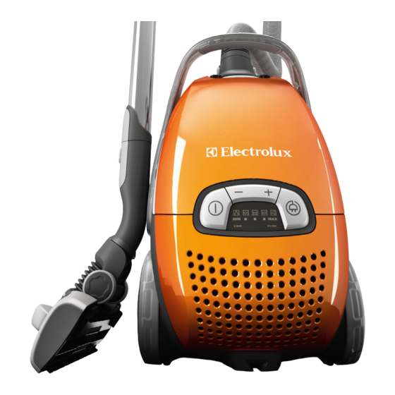
1 General description Display Hepa filter cover Hepa filter Parking slot Power cord Motor filter Motor filter holder S-bag® Dust compartment cover Button for Aeropro 3in1, dust bag compartment Aeropro 3in1 compartment Aeropro 3in1 nozzle Aeropro hose Handle Aeropro telescopic tube Parking clip Display for models with manual control Aeropro classic handle... -
Page 4: Exploded View
1.1 Exploded view Publication number Rev. 01 02/2009 PR - 4/42 599 71 19-22... - Page 5 Description Description Description BASE HOSE CONNECTION INNER CLIP PARKING MOTOR HOUSING BUTTON FRONT COVER ABSORBER FILTER LID FRONT COVER CORDWINDER LEVER FRAME HOSE CONNECTION BUTTON FRONT LID DISPLAY BASE SIDE FRAME LEFT FRONT LID FRONT WHEEL ROLL COMPLETE SOFT PCB CONTROL UNIT REAR COVER FRONT WHEEL HOLDER POWER SUPPLY UNIT AEROPRO...
-
Page 6: Accessibility
ACCESSIBILITY The following chapter follows a disassembling process that step by step will allow the Technician to completely dismount the vacuum cleaner. Tags have been added to help finding quickly the needed item to be removed quickly. The following sections are outlined: Dust bag cover and compartment Display cover PCB Display/Switch... - Page 7 Dust bag cover and compartment Release the two rear tabs of the grill filter Completely detach the grill filter Remove the sponge Remove the Hepa filter Press the lock covers Open the dust bag cover Lift up the lock cover of the lid Publication number Rev.
- Page 8 Release the right anchor of the dust Release the left anchor bag cover Detach the lock using a fine-tipped screwdriver Carefully detach this part Remove completely the part Remove the spring Detach the lock using a fine-tipped Carefully detach this part screwdriver Publication number Rev.
- Page 9 Release the right anchor of the lid accessory Release the anchor and remove Remove the spring from the dust bag the lid accessory cover Publication number Rev. 01 02/2009 PR - 9/42 599 71 19-22...
- Page 10 Display cover Detach the side cover using a fine- tipped screwdriver Detach the side cover using a fine- tipped screwdriver Lift up the display cover Remove completely the display cover Detach the ON/OFF button lever Detach the ON/OFF button using a Detach the cord winder button using a fine-tipped screwdriver fine-tipped screwdriver...
- Page 11 Detach from the outside the power Remove the springs from the buttons button using a fine-tipped screwdriver Detach from the inside the power button using a fine-tipped screwdriver Remove completely the power button Publication number Rev. 01 02/2009 PR - 11/42 599 71 19-22...
- Page 12 PCB Display/Switch Detach the pressostat hose Remove the PCB with the Detach the PCB supply cable reflector on it Detach the reflector tab from the board using a fine-tipped screwdriver ATTENTION: Boards and electronic devices could be damaged by electrostatic discharges. Don’t touch any components without any ESD protection.
- Page 13 Top cover Remove the screws that fix the top Detach the top cover using a fine- cover tipped screwdriver Detach the top cover using a fine- Detach the top cover using a fine- tipped screwdriver tipped screwdriver Detach the top cover using a fine- Detach the top cover using a fine- tipped screwdriver tipped screwdriver...
- Page 14 Remove completely the top cover from Remove completely the top cover from the back the front Publication number Rev. 01 02/2009 PR - 14/42 599 71 19-22...
- Page 15 Housing Remove the seven screws that fix the housing of the cleaner Remove the gasket from its site Remove completely the holder of Remove the filter from the holder motor filter using a fine-tipped Lift up the complete housing of the cleaner keeping firmly down Publication number Rev.
- Page 16 Cord winder Detach the cord winder button lever Remove completely the cord winder using a fine-tipped screwdriver button pin Remove the screws that keep the cord Remove the screws that keep the cord winder assy winder assy Remove the screw from the cord winder cover Lift up the cord winder cover Detach the pressostat hose...
- Page 17 Remove completely the cord winder Publication number Rev. 01 02/2009 PR - 17/42 599 71 19-22...
- Page 18 Handle Detach the left handle cover using a fine-tipped screwdriver Remove completely the left handle Detach the right handle cover using a cover fine-tipped screwdriver Detach the right handle cover using a Remove completely the right handle fine-tipped screwdriver cover Remove the screw on the right side Remove the screw on the left side Publication number...
- Page 19 Detach the internal rubber part of the Detach the internal rubber part of the handle using a fine-tipped screwdriver handle using a fine-tipped screwdriver Detach the internal rubber part of the Remove completely the internal rubber handle using a fine-tipped screwdriver part using a fine-tipped screwdriver Remove the two screws on the front Detach the locking pin on the handle...
- Page 20 Wheels Detach the wheel covers using a fine- Remove the screws; reach them tipped screwdriver through the holes on the wheel Remove the locking clip on the wheel Detach the two clips on the axe using shaft a fine-tipped screwdriver Remove completely the axe from the Remove completely the wheel shaft wheel...
- Page 21 Remove the screws that fix the metal plate to the structure Publication number Rev. 01 02/2009 PR - 21/42 599 71 19-22...
- Page 22 Power module and power supply unit Aeropro Detach the connectors using a fine- Detach the connection tipped screwdriver Detach the pressostat hose Detach the connectors using a fine- tipped screwdriver Detach the connection Detach the power module PCB using Detach the power supply unit Aeropro a fine-tipped screwdriver using a fine-tipped screwdriver Publication number...
- Page 23 Motor Remove the screws that keep joined Detach the pressostat hose the two housing Remove the screws that keep joined the two housing Separate the two housing Lift up the blower seal Remove completely the blower seal Remove completely the motor Publication number Rev.
- Page 24 Remove the absorber outer filter Remove the motor’s cover Publication number Rev. 01 02/2009 PR - 24/42 599 71 19-22...
- Page 25 HBTN Nozzle Telescope tube Remove the screw using a torx Bent end screwdriver Remove the screw using a torx screwdriver Detach the top cover Remove 3 screws using a fine-cross Detach the complete brush lever screwdriver system Publication number Rev. 01 02/2009 PR - 25/42 599 71 19-22...
- Page 26 Detach the lever from the cover Detach the wheel cover using a fine- tipped screwdriver Remove the screw using a fine-cross screwdriver Remove 2 screws using a fine-cross Detach the hose from the brush screwdriver Publication number Rev. 01 02/2009 PR - 26/42 599 71 19-22...
- Page 27 Detach the cover from the hose Detach the remote control using a fine-tipped screwdriver Detach the cover using a fine-tipped screwdriver Publication number Rev. 01 02/2009 PR - 27/42 599 71 19-22...
-
Page 28: Levels Of Electronic Control
3 Levels of Electronic Control 3.1 Display Layout for models without remote controlled HBTN: 3.1.1 Basic software functionality ON/OFF switch Soft-start, function according to chapter “Softstart and motor power change”. Automatic 50/60Hz detection. When started, raise power to maximum power. ( + ) increase motor power, one press increase power with one step. -
Page 29: Display Layout For Models With Rf Controlled Hbtn
3.2 Display Layout for models with RF controlled HBTN: 3.2.1 Basic software functionality ON/OFF switch Soft-start Automatic 50/60Hz detection. When started from unplugged, cleaner starts in AUTO mode, otherwise in last used mode. Toggle between cleaning modes, 5 manual power steps. Power indication, “fading light”. - Page 30 - Motor turns off; last power setting and mode is remembered by the microcontroller. - LED indication shows the last used power setting by flashing the corresponding LED with 1Hz, same function as for level 1. 7. Cleaner is turned on by one of the On/Off switches after being at point 6: - Motor turns on and run into manual mode, and starts at the last used power setting.
-
Page 31: Display Layout For Models With Aeropro Active System
3.3 Display Layout for models with Aeropro active system: 3.3.1 Basic Software functionality ON/OFF switch Soft-start Automatic 50/60Hz detection When started from unplugged, cleaner starts in AUTO mode, otherwise in last used mode. Toggle between cleaning modes, 5 manual power steps. Power indication, “fading light”. -
Page 32: Nozzle Power Supply Interface
3.4 Nozzle power supply interface For vacuum cleaners with AUTO mode function: button 1 turns on or off the cleaner button 2 turns on or off the nozzle motor (handled by the Aeropro PCB) button 3 turns on the cleaner into AUTO mode button 4 turns on the cleaner into manual mode and toggles the manual 5 power steps... -
Page 33: Isometric View Of All Pcb-Versions
Keep the ON/OFF button pressed until the AUTO LED:s start flashing, the cleaner is now in RF learning mode. Release the ON/OFF button. On the remote control press the ON/OFF button. If the cleaner have received the new RF remote address the power bar will start flashing, indicating that the learning process is finalized. -
Page 34: Auto Function, Pressure Sensor Pcb (Position 014D)
3.7 Auto function, pressure sensor PCB (position 014D) Auto function is a function for automatically regulate the motor power depending on the air pressure. To the control PCB a pressure switch/sensor PCB is connected. The control PCB senses that the auto board is connected and activates the software for automatic power regulation. -
Page 35: Pcb Power Module (Position 014A)
4 PCB Power Module (position 014A) 4.1 Introduction Power module is intended as a module PCB for mainly vacuum cleaners from Electrolux Floor Care & Small Appliances AB. The module is intended to consist of a Triac, triggering a motor, and a power supply for additional connected electronic. -
Page 36: Low Current Power Module
4.3 Low Current Power Module The low current power module contains a capacitive power supply. The low current power module can always be replaced by a high current power module, or International power module (see parts lists). 4.3.1 Power supply design low current power module The 5V power supply is of the type capacitive supply. -
Page 37: Rf Transmitter
5 RF transmitter 5.1 Introduction The RF transmitter is used as remote control for a vacuum cleaner powered by a 3V changeable lithium cell. The transmitter uses the 433MHz band for transmitting data inside EU. With the transmitter it is possible to turn the appliance on and off, and regulate the motor power. -
Page 38: Aeropro Pcb 230V/110V Motor
6 Aeropro PCB 230V/110V motor 6.1 Introduction Aeropro PCB 230V is a new PCB to support the drive of a 230VAC motor mounted in the Aeropro nozzle. The motors continuously current consumption is maximum 1A. The PCB can also be used without nozzle motor, and then only support a wired remote control between the cleaners bent end and the cleaners control unit. -
Page 39: Functional Description
- M2 GND. Note: live voltage potential. The controller on the Aeropro PCB reads the analog signal level, and converts the signal to a frequency output signal, which is communicated to the Elara control PCB. 6.5 Motor output The on/off of the motor nozzle is controlled by a Triac. -
Page 40: Deactivation
7.1.2 Deactivation To deactivate the LED indicator after activation this can be made in three ways. First is to disconnect and reconnect the main connector. Also this can be made by turning off the cleaner, turn it on again and keep the on/off button pressed for 5 seconds. -
Page 41: Trouble Shooting
8 TROUBLE SHOOTING Problem Checks Cleaner without remote: Investigate if the plastic knob reaches the ON/OFF switch on the PCB. Replace the control unit (display PCB) Cleaner with radio remote: Investigate if both ON/OFF (cleaner and remote) is not working. If remote ON/OFF working, but not cleaner ON/OFF: Investigate if the plastic knob reaches the ON/OFF switch on the PCB. - Page 42 Cleaner with radio remote: Investigate if the LED on the remote indicates transmission. If not, change battery and try again. If still no LED indication on remote, change remote control and reprogram the cleaner according to above instruction. If LED indicates transmission, try replacing the remote according to above instruction.
Need help?
Do you have a question about the Elara and is the answer not in the manual?
Questions and answers