Advertisement
SERVICE MANUAL
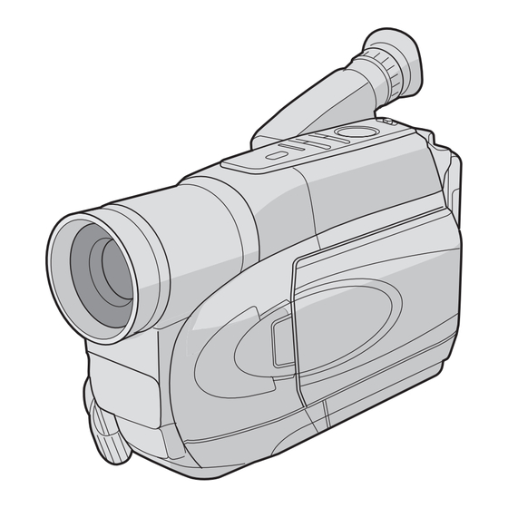
COMPACT VHS CAMCORDER
YF036
2004
2
GR-SXM277UA,GR-SXM277UM,
GR-SXM278UM,GR-SXM279UB,GR-SXM279UM
GR-SXM277UA, GR-SXM277UM, GR-SXM278UM, GR-SXM279UB, GR-SXM279UM [M4C623]
For disassembling and assembling of MECHANISM ASSEMBLY, refer to the SERVICE MANUAL No.86700 (MECHANISM ASSEMBLY).
Regarding service information other than these sections, refer to the service manual No. YF016 (GR-SXM260US).
Also, be sure to note important safety precautions provided in the service manual.
No.YF036
COPYRIGHT © 2003 VICTOR COMPANY OF JAPAN, LIMITED
2004/2
Advertisement
Table of Contents

Related Manuals for JVC GR-SXM277UA


Summary of Contents for JVC GR-SXM277UA
- Page 1 2004 GR-SXM277UA,GR-SXM277UM, GR-SXM278UM,GR-SXM279UB,GR-SXM279UM GR-SXM277UA, GR-SXM277UM, GR-SXM278UM, GR-SXM279UB, GR-SXM279UM [M4C623] For disassembling and assembling of MECHANISM ASSEMBLY, refer to the SERVICE MANUAL No.86700 (MECHANISM ASSEMBLY). Regarding service information other than these sections, refer to the service manual No. YF016 (GR-SXM260US). Also, be sure to note important safety precautions provided in the service manual.
- Page 2 SPECIFICATION (The specifications shown pertain specifically to the model GR-SXM277UM/GR-SXM278UM/GR-SXM279UM) DIFFERENT TABLE OF FEATURE The following table indicate main different points between models GR-SXM260US, GR-SXM277UA, GR-SXM277UM, GR-SXM278UM, GR-SXM279UB and GR-SXM279UM. MODEL GR-SXM260US GR-SXM277UA GR-SXM277UM GR-SXM278UM GR-SXM279UB GR-SXM279UM BODY COLOR SILVER...
-
Page 3: Parts List
Parts identified by the symbol are critical for safety. Replace only with specified part numbers. 1. EXPLODED VIEW 1.1 PACKING AND ACCESSORY ASSEMBLY <M1> The instruction manual to be provided with this product will differ according to the destination. FINAL ASSEMBLY <M2> MODEL MARK GR-SXM277UA GR-SXM277UM GR-SXM278UM GR-SXM279UB GR-SXM279UM LABEL (SERIAL) (No.YF036)3-1... - Page 4 1.2 FINAL ASSEMBLY <M2> BEWARE OF BOGUS PARTS Parts that do not meet specifications may cause trouble in regard to safety and performance. We recommend that genuine JVC parts be used. E.VF ASSEMBLY <M4> MAIN BOARD ASSEMBLY <01> 121B 121A...
- Page 5 145A 145E 145B 145G 145D 145C MECHANISM 145D ASSEMBLY <M3> 145F 145F 145D 145D RATING LABEL 101E 101A 101C 101D 101G MONITOR 101E ASSEMBLY <M5> 103A 101G 101B (No.YF036)3-3...
- Page 6 1.3 MECHANISM ASSEMBLY <M3> BEWARE OF BOGUS PARTS Parts that do not meet specifications may cause trouble in regard to safety and performance.We recommend that genuine JVC parts be used. 469A 469B 469B 439A 429A 450 a 406B 406A YMA0046A-E...
- Page 7 YMA0046A-E 489B 489A (No.YF036)3-5...
- Page 8 1.4 E.VF ASSEMBLY <M4> E.VF BOARD ASSEMBLY <60> 357A SERIAL NO. LABEL 3-6(No.YF036)
- Page 9 1.5 MONITOR ASSEMBLY <M5> 501A MONITOR BOARD ASSEMBLY <07> 502C 502B 502A (No.YF036)3-7...
- Page 10 MODEL MARK MODEL MARK GR-SXM277UA GR-SXM279UB GR-SXM277UM GR-SXM279UM GR-SXM278UM 2. PARTS LIST PACKING AND ACCESSORY ASSY <M1> Symbol No. Part No. Part Name Description Local Symbol No. Part No. Part Name Description Local 135D QYSLSF1770DA TAP SCREW (x3)
- Page 11 MODEL MARK MODEL MARK GR-SXM277UA GR-SXM279UB GR-SXM277UM GR-SXM279UM GR-SXM278UM Symbol No. Part No. Part Name Description Local MONITOR ASSEMBLY <M5> Symbol No. Part No. Part Name Description Local LY30162-002A POLE BASE(T)ASSY LY42523-002A DRIVE LEVER ASSY LY44000-002A SLANT ARM ASSY ...
- Page 12 MODEL MARK MODEL MARK GR-SXM277UA GR-SXM279UB GR-SXM277UM GR-SXM279UM GR-SXM278UM Symbol No. Part No. Part Name Description Local Symbol No. Part No. Part Name Description Local Q105 or BC847BT-X TRANSISTOR TAPE_LED Q7002 or UMX1N-W PAIR TRANSISTOR Q114 2SC4617/QR/-X TRANSISTOR...
- Page 13 MODEL MARK MODEL MARK GR-SXM277UA GR-SXM279UB GR-SXM277UM GR-SXM279UM GR-SXM278UM Symbol No. Part No. Part Name Description Local Symbol No. Part No. Part Name Description Local C1618 NCB31CK-683X C CAPACITOR 0.068uF 16V K C4040 NCF31EZ-104X C CAPACITOR 0.1uF 25V Z...
- Page 14 MODEL MARK MODEL MARK GR-SXM277UA GR-SXM279UB GR-SXM277UM GR-SXM279UM GR-SXM278UM Symbol No. Part No. Part Name Description Local Symbol No. Part No. Part Name Description Local C6035 NCB31CK-104X C CAPACITOR 0.1uF 16V K R128 NRSA63J-823X MG RESISTOR 82kΩ 1/16W J...
- Page 15 MODEL MARK MODEL MARK GR-SXM277UA GR-SXM279UB GR-SXM277UM GR-SXM279UM GR-SXM278UM Symbol No. Part No. Part Name Description Local Symbol No. Part No. Part Name Description Local R1615 NRSA63J-102X MG RESISTOR 1kΩ 1/16W J R4217 NRSA63J-102X MG RESISTOR 1kΩ 1/16W J...
-
Page 16: Ccd Board
3.3kΩ 1/16W D CN12 QGA1501F2-03V CONNECTOR B/W.VF 3P W-B (1-3) R7004 NRSA63D-123X MG RESISTOR 12kΩ 1/16W D CN13 QGF0534F1-14X CONNECTOR JVC Z.OPE FFC/FPC (1-14) R7005 NRSA63J-223X MG RESISTOR 22kΩ 1/16W J CN15 QGF0534F1-24X CONNECTOR OP FFC/FPC (1-24) R7006 NRSA63D-332X MG RESISTOR 3.3kΩ... - Page 17 MODEL MARK MODEL MARK GR-SXM277UA GR-SXM279UB GR-SXM277UM GR-SXM279UM GR-SXM278UM Symbol No. Part No. Part Name Description Local Symbol No. Part No. Part Name Description Local C5304 NCF31EZ-104X C CAPACITOR 0.1uF 25V Z R7501 NRSA63J-102X MG RESISTOR 1kΩ 1/16W J...
- Page 18 MODEL MARK MODEL MARK GR-SXM277UA GR-SXM279UB GR-SXM277UM GR-SXM279UM GR-SXM278UM Symbol No. Part No. Part Name Description Local C7008 NCF21CZ-105X CAPACITOR 1uF 16V Z C7009 PECA1131-A107 E CAPACITOR 100uF 10V C7010 CM316UJ472J100A CAPACITOR 0.0056uF 100V C7011 NDC21HJ-180X CAPACITOR 18pF 50V J...
-
Page 19: Table Of Contents
SERVICE MANUAL COMPACT VHS CAMCORDER YF016 2004 GR-SXM161US,GR-SXM256UC, GR-SXM260UC,GR-SXM260US, GR-SXM265UC,GR-SXM265US GR-SXM161US[M4C623],GR-SXM256UC[M4C622] GR-SXM260UC/US[M4C623],GR-SXM265UC/US[M4C623] For disassembling and assembling of MECHANISM ASSEMBLY, refer to the SERVICE MANUAL No.86700 (MECHANISM ASSEMBLY). TABLE OF CONTENTS PRECAUTION............... . . 1-3 SPECIFIC SERVICE INSTRUCTIONS . -
Page 20: No.yf016)1
SPECIFICATION (The specifications shown pertain specifically to the model GR-SXM260) 1-2 (No.YF016) -
Page 21: Precaution
SECTION 1 PRECAUTION SAFTY PRECAUTIONS Prior to shipment from the factory, JVC products are strictly emission. Consequently, when servicing these products, inspected to conform with the recognized product safety and replace the cathode ray tubes and other parts with only the electrical codes of the countries in which they are to be specified parts. - Page 22 1.1.2 Safety Check after Servicing Examine the area surrounding the repaired location for damage (4) Leakage current test or deterioration. Observe that screws, parts and wires have been Confirm specified or lower leakage current between earth returned to original positions, Afterwards, perform the following ground/power cord plug prongs and externally exposed tests and confirm the specified values in order to verify accessible parts (RF terminals, antenna terminals, video...
-
Page 23: Specific Service Instructions
SECTION 2 SPECIFIC SERVICE INSTRUCTIONS DIFFERENCE LIST The following table indicate main different points between models GR-SXM161US, GR-SXM256UC, GR-SXM260UC, GR-SXM260US, GR-SXM265UC and GR-SXM265US. MODEL GR-SXM161US GR-SXM256UC GR-SXM260UC GR-SXM260US GR-SXM265UC GR-SXM265US DC LIGHT BODY COLOR BLUE SILVER SILVER SILVER BLUE BLUE CASSETTE ADAPTER C-P7U C-P7U... -
Page 24: Disassembly
SECTION 3 DISASSEMBLY BEFORE ASSEMBLY AND DISASSEMBLY • 3.1.1 Precautions Torque driver • Be sure to disconnect the power supply unit prior to mounting Be sure to use to fastening the mechanism and exterior parts and soldering of parts. because those parts must strictly be controlled for tightening •... - Page 25 3.2.2 ASSEMBLY/DISASSEMBLY OF CABINET PARTS AND ELECTRICAL PARTS Disassembly procedure Destination of connectors STEP Fig. PART NAME POINT NOTE CN.NO. CONNECTOR LOWER CASE ASSEMBLY Fig.C1 8(S1),CN1a,b,c CN1a MAIN CN27 SPEAKER B/W VF ASSEMBLY 3(S2) CN1b MAIN CN13 ZOOM UNIT TOP OPE UNIT(S) CN3,(S3),(L3a),(L3b),2(L3d) CN1c MAIN...
- Page 26 <BOTTOM SIDE> OP BLOCK ASSEMBLY (S3) CN1a CN1b CN1c (S1) 9 (S2) 10 (S2) 11 (S2) (S1) (S1) (S1) (S1) (S1) (S1) (S1) Fig.C1 <S : SHOOTING MODEL> (S4) <M : MONITOR MODEL> Fig.C2 1-8 (No.YF016)
- Page 27 (S5a) <NOTE 5> <S : SHOOTING MODEL> (S5a) (S5a) (S5a) (S5a) <M : MONITOR MODEL> <NOTE 5> (S5a) (S5b) (S5a) (L5) (S5a) (S5a) (S5a) (S5a) Fig.C3 <MONITOR MODEL> (S7b) <NOTE 7a> (S7b) (S7a) <NOTE 7c> (S6) DO NOT MAKE FPC (S6) SLACKEN IN THIS PART.
- Page 28 0.118N m (1.2kgf (S8) (S11) <NOTE 8a> [11] OP BLOCK ASSEMBLY (S11) <NOTE 8b> CN8a PASS THE WIRE BETWEEN THESE BOSSES. LIGHT WIRE CN8b DO NOT OBSTRUCT THE RECEIVING SHIELD SCREWING SEQUENCE PART OF SENSOR SHOULD BE IN ORDER BY WIRE . HERE FIRST AND OTHERS .
- Page 29 3.2.3 ASSEMBLY AND DISASSEMBLY OF CAMERA SECTION AND BOARD ASSEMBLY Disassembly procedure STEP Fig. POINT NOTE PART MAIN BOARD ASSEMBLY Fig.D1 CN1a,b,c,d,e,f,g,h,SHIELD 2(S1),L1,CN1j OP BLOCK ASSEMBLY Fig.D2 2(S2) NOTE 3 CCD BOARD ASSEMBLY (S4a),(S4b),L4 NOTE 4 MECHANISM ASSEMBLY Fig.D3 SHIELD CASE(MAIN) 2(S4c),(S4d) 2(S5) REAR BOARD ASSEMBLY...
- Page 30 (S4d) (S4c) FRAME ASSEMBLY CN1h CN1g C2 J CN1f <NOTE 4> SHIELD CASE (MAIN) CN1a CN1b (S4c) CN1j CN1d CN1c (S1) CN1e (S1) SHIELD (S4a) (S4b) Fig.D1 Fig.D3 (S2) (S2) <NOTE 3> FRAME ASSEMBLY (S5) (S5) Fig.D2 Fig.D4 1-12 (No.YF016)
- Page 31 3.2.4 ASSEMBLY AND DISASSEMBLY OF [7]MONITOR ASSEMBLY (CABINET PARTS) Disassembly of MONITOR ASSEMBLY NOTE : Be careful not to soil or scratch the monitor screen through the disassembly/assembly work. (1) While removing the three screws 1 to 3 in numerical order and disengaging the three hooks (L7a and L7b) (S7a) in alphabetical order, remove the MONITOR COVER...
- Page 32 3.2.5 ASSEMBLY AND DISASSEMBLY OF [2]OP BLOCK ASSEMBLY CCD BOARD ASSEMBLY (CAMERA SECTION AND BOARD ASSEMBLY) Precautions Assembly of CCD BASE ASSEMBLY and CCD BOARD AS- (1) Take care in handling the CCD IMAGE SENSOR, OP SEMBLY LPF and lens components when performing mainte- (1) Set the OP LPF to the OP BLOCK ASSEMBLY so that nance etc., especially with regard to surface contamina- the OP side touches the OP BLOCK ASSEMBLY.
-
Page 33: Adjustment
SECTION 4 ADJUSTMENT PREPARATION 4.1.3 TOOLS REQUIRED FOR ADJUSTMENT 4.1.1 Precaution Alignment tape Alignment tape Cassette torque meter MHP-C MHP-LC PUJ50431-2 Camera system and deck system of this model are specially adjusted by using PC. However, if parts such as the following are replaced, an adjustment is required. - Page 34 • Conn. ring JIG CONNECTOR CABLE CONNECTION The connector ring to attach the INF lens to the head of the OP Connection procedure lens. For the usage of the Conn.ring. • INF Adjustment Lens To be used for adjustment of the camera system. For the us- age of the INF adjustment lens, refer to the Service Bulletin No.
- Page 35 MECHANISM COMPATIBILITY ADJUSTMENT 4.3.1 Tape transport adjustment BACK TENSION Mechanism adjustment is needed when DRUM ASSEMBLY or a 0.97x10 - 1.71x10 • PLAY TORQUE (10-17gf·cm) part of the tape transport system is replaced. To protect tapes 1.47x10 - 2.45x10 N·m from damage, first clean the tape transport system, next confirm (15-25gf·cm) that nothing is wrong with the tape transport system by using a...
- Page 36 (7) By operating the tracking button (both in + and - directions) 4.3.4 A/C head height & azimuth in the manual tracking mode, vary the output level of the Remove the exterior parts attached to the UPPER CASE FM waveform from maximum to minimum and vice versa to ASSEMBLY so that the screws around the A/C HEAD confirm that the waveform varies nearly in a flat shape.
- Page 37 4.3.5 Phase of control head (X value) ELECTRICAL ADJUSTMENT Note: Electrical adjustment is performed by using a personal computer Remove the exterior parts attached to the UPPER CASE and software for SERVICE SUPPORT SYSTEM. Read RE- ASSEMBLY so that the screws around the A/C HEAD ADME.TXT file to use the software properly.
- Page 38 4.4.1.1 Tilt Subject • Alignment tape • Stairstep Mode • PB Equipment • E. VF Measurement point • E. VF screen Adjusting part • Deflection yoke Specification • The picture is visible as same as monitor TV. (1) Put the deflection yoke to the most inner side of CRT neck first.
-
Page 39: Troubleshooting
SECTION 5 TROUBLESHOOTING SERVICE NOTE (No.YF016)1-21... - Page 40 5.2 TAKE OUT CASSETTE TAPE In the event that the set enters the emergency mode as it is (4) While holding down the cassette housing by hand, con- loaded with a cassette tape and the cassette tape cannot be nect the jumper wires to a battery to run the mechanism ejected with the EJECT button, manually, take it out of the set to the EJECT position four unloading.
- Page 41 5.3 EMERGENCY DISPLAY Example (in case of the error number E01): Whenever some abnormal signal is input to the mechacon CPU, an error number (E01, as an example) is displayed in the elec- tronic view finder. In every error status, such the message as UNIT IN REMOVE AND shown below alternately appear over and over.
- Page 42 JVC SERVICE & ENGINEERING COMPANY OF AMERICA DIVISION OF JVC AMERICAS CORP. www.jvcservice.com(US Only) JVC CANADA INC. Head office : 21 Finchdene Square Scarborough, Ontario M1X 1A7 (416)293-1311 (No.YF016) Printed in Japan...
- Page 43 SCHEMATIC DIAGRAMS COMPACT VHS CAMCORDER YF016 2004 GR-SXM161US,GR-SXM256UC, GR-SXM260UC,GR-SXM260US, GR-SXM265UC,GR-SXM265US CD-ROM No.SML200402 GR-SXM161US[M4C623],GR-SXM256UC[M4C622] GR-SXM260UC/US[M4C623],GR-SXM265UC/US[M4C623] For disassembling and assembling of MECHANISM ASSEMBLY, refer to the SERVICE MANUAL No.86700 (MECHANISM ASSEMBLY). No.YF016SCH COPYRIGHT © 2004 VICTOR COMPANY OF JAPAN, LIMITED 2004/1...
- Page 44 CHARTS AND DIAGRAMS NOTES OF SCHEMATIC DIAGRAM 4) Indication on schematic diagram Voltage Indications for REC and PB mode on the sche- Safety precautions matic diagram are as shown below. The Components identified by the symbol critical for safety. For continued safety, replace safety critical components only with manufacturer's recom- REC mode mended parts.
- Page 45 6. Signal path Symbols CIRCUIT BOARD NOTES The arrows indicate the signal path as follows. 1. Foil and Component sides 1) Foil side (B side) : Playback signal path Parts on the foil side seen from foil face (pattern face) are indicated.
-
Page 46: Board Interconnections
BOARD INTERCONNECTIONS CN7502 BL_GND (Page2-29) (Not Used) CN9012 CN16 BWYGAIN BWYOUT REG_-15V REG_15V (Page2-21) REG_4.8V (Page2 DAC_3.2V REG_3.2V V_PLS_ON REG+12V V_PB_F V_REC_C V_REC_F 2FSC S_DET+ SPK_VOL SH_SIG BWVFADJ DAC_3.2V VF_BLK REG+12V REG_4.8V (Page2-23) BWYGAIN BWYOUT V_PLS_ON BWBLEVEL BW_VF_Y VF_BL4.8 VF_CTL V_FF SCK3 CN28... - Page 47 NOTE : :The number of patch cords are indicated by interconnected. 6 0 E.VF(B/W) (Page2-31) JIG CONN. CABLE YTU93082G (Page2-28) YTU94074-24 YTU64077-24 YUJ40095A-3 YTU94074-14 CN25 YTU94077-14 CN12 CN22 CN15 AD_0 AD_0 AD_1 AD_1 AD_2 AD_2 REG_4.8V SCK3 AD_3 AD_3 REG_3.2V AD_4 AD_4 AD_5...
- Page 48 MAIN(CPU) SCHEMATIC DIAGRAM UNREG R104 CN13 BD4827FVE-W CN13 2SA1774/RS/-X VOUT R101 CN18 2SC4617/QR/-X Q101 R107 R108 100K CN18 IC104 Q103 R112 D102 CN9013 Q105 R109 R106 2SC4617/RS/-X CN9013 2.2K R111 C110 C108 µ C109 100p R114 C103 C104 3.3K AL_3.2V Q102 C105 L101...
- Page 49 NOTES : For the destination of each signal and further line connections that are cut off from this diagram, refer to "BOARD INTERCONNECTIONS". When ordering parts, be sure to order according to the Part Number indicated in the Parts List. CTL_ERS- R172 TAPE_VCC...
- Page 50 MAIN(M.MDA) SCHEMATIC DIAGRAM 0 1 MAIN(M.MDA) DRUM_PG DRUM_FG CAP_FG DRUM_REF CAP_REF C_FR B L_FR B MDA_PS D.PCV D.COM D. U D. V D.RNF R1602 0.33 D. W C1628 L.FR B IC1601 L.REF R1612 BD6637KV C1614 L.FW D R1613 0.01 LOAD_FWD LOAD_REV L.GND L.REV...
- Page 51 NOTES : For the destination of each signal and further line connections that are cut off from this diagram, refer to "BOARD INTERCONNECTIONS". When ordering parts, be sure to order according to the Part Number indicated in the Parts List. TP1607 DRUM_ERR DRUM_PWR...
- Page 52 MAIN(ASP) SCHEMATIC DIAGRAM CN25 V_OVL AO_SIG_J PB_CTL V_FF V_TP_FM FEH_ON V_ENV V_FF SCK3 V_ASP_CS CTL_OUT REC_CTL A_BIAS A_PB A_MUTE L3502 22µ APB_EP_H SPK_VOL C3513 0.022 REG_4.8V REG_3.2V R3506 REG_4.8V CTL_HED- CTL_HED+ L2004 AH_PB AH_REC L2005 AH_GND C1201 1000p L2001 JP2001 47µ...
- Page 53 NOTES : For the destination of each signal and further line connections that are cut off from this diagram, refer to "BOARD INTERCONNECTIONS". When ordering parts, be sure to order according to the Part Number indicated in the Parts List. V_OVL 2FSC V_PB_F...
- Page 54 MAIN(DSP) SCHEMATIC DIAGRAM SDET_CTL CDS_CLK V_PULS CDS_CLK AD_9 AD_9 AD_8 AD_8 AD_7 AD_7 AD_6 AD_6 AD_5 AD_5 AD_4 C4009 X4001 AD_4 QAX0709-001 AD_3 AD_3 AD_2 C4010 AD_2 AD_1 XOUT R4002 AD_1 AD_0 VDD12 AD_0 SCK3 C4011 SDCK V_DSP_CS LHFO LHFO GND12 HDTG C4008...
- Page 55 NOTES : For the destination of each signal and further line connections that are cut off from this diagram, refer to "BOARD INTERCONNECTIONS". When ordering parts, be sure to order according to the Part Number indicated in the Parts List. DAC5 BWYGAIN DAC4...
- Page 56 MAIN(F/Z/MDA) SCHEMATIC DIAGRAM IRIS_O/C IRIS_PWM HALL_A/D H_OFFSET R4210 H_GAIN IR_DC C4205 0.01 IR_FLICK R4205 R4258 C4253 0.015 100K 820K R4256 R4257 8.2K C4256 C4254 0.015 R4259 Q4251 RPM-22PB R4214 4.7k R4251 1.8K R4253 C4203 R4255 2.2K L4201 NQR0006-001X REG_4.8V R4254 680K C4201 C4202...
- Page 57 NOTES : For the destination of each signal and further line connections that are cut off from this diagram, refer to "BOARD INTERCONNECTIONS". When ordering parts, be sure to order according to the Part Number indicated in the Parts List. DUMP+ R4206 R4207...
- Page 58 MAIN(V-OUT) SCHEMATIC DIAGRAM REG_4.8V DAC_3.2V R4704 1.2k C4702 C4704 R4703 Q4701 CAM_Y 2SA1774 R4701 C4703 C4701 R4710 1.2K C4716 C4705 0.01 R4709 Q4702 CAM_C 2SA1774 R4707 C4717 NOTES : 1. The parts with marked( ) is not used. 2. For V-OUT waveforms,please refer to page 2-43. 2-15...
- Page 59 NOTES : For the destination of each signal and further line connections that are cut off from this diagram, refer to "BOARD INTERCONNECTIONS". When ordering parts, be sure to order according to the Part Number indicated in the Parts List. L4701 CN25 22µ...
- Page 60 MAIN(TG/CDS) SCHEMATIC DIAGRAM 1 MAIN(TG/CDS) CN22 C5231 1SS355-X CCD_OUT D5201 R5212 CCD_HV 100k C5222 CCD_LV IC5202 MN31121SA-X ISUB R5203 C5226 R5204 R5205 VM13 C5223 R5206 VM24 OSUB C5225 R5208 C5211 C5212 C5224 µ C5213 NOTES : 1. The parts with marked( ) is not used. 2.
- Page 61 NOTES : For the destination of each signal and further line connections that are cut off from this diagram, refer to "BOARD INTERCONNECTIONS". When ordering parts, be sure to order according to the Part Number indicated in the Parts List. L5203 µ...
- Page 62 MAIN(REG) SCHEMATIC DIAGRAM 0 1 MAIN(REG) F6001 NMFZ007 R6003 R6001 L6001 IC6002 IC6003 Q6002 R6009 L6002 10µ R6010 R6011 Q6001 R6043 C6021 RA6001 IC6001 FA3698F C6046 R6039 560p C6027 0.0047 R6033 R6032 5.6K C6028 C6029 0.001 C6030 R6045 0.001 0Ω C6031 R6046 0.001...
- Page 63 NOTES : For the destination of each signal and further line connections that are cut off from this diagram, refer to "BOARD INTERCONNECTIONS". When ordering parts, be sure to order according to the Part Number indicated in the Parts List. M_UNREG R6042 0Ω...
- Page 64 MAIN(LCD) SCHEMATIC DIAGRAM Q7001 Q7002 L7002 22µ PUMX1-W PUMX1-W OPEN_SW OPEN_SW LCD_CTL LCD_CTL REV_SW REV_SW PMIRROR PMIRROR R7018 R7019 DSP_REST DSP_REST HRP1 HRP1 VDCVF VDCVF HDCVF HDCVF C7006 ROUT C7007 GOUT BOUT REG_15V REG+12V REG_4.8V DAC_3.2V REG_3.2V REG_-15V NOTE : The parts with marked( ) is not used. 2-21...
- Page 65 NOTES : For the destination of each signal and further line connections that are cut off from this diagram, refer to "BOARD INTERCONNECTIONS". When ordering parts, be sure to order according to the Part Number indicated in the Parts List. CN16 OPEN_SW OPEN_SW...
- Page 66 MAIN(BWVF) SCHEMATIC DIAGRAM 0 1 MAIN(BWVF) BWBLEVEL IC9302 C931 MCU_RST LCD_CTL R9328 D9301 REG+12V VF_CTL C9318 VDDH REG_4.8V L9303 CN25 TEST BWVFADJ IC9301 L9302 SEL_PDR VBAT C9319 A_VBAT C9320 HDCVF H_SYNC VDCVF V_SYNC V_PLS_ON VHIO_SEL BWYGAI N BWYOUT R7301 DAC_3.2V 1.0k CN12 BW_VF_Y...
- Page 67 NOTES : For the destination of each signal and further line connections that are cut off from this diagram, refer to "BOARD INTERCONNECTIONS". When ordering parts, be sure to order according to the Part Number indicated in the Parts List. Q9303 CN9012 C9312...
- Page 68 MAIN (JACK) SCHEMATIC DIAGRAM CN9031 R9402 R9403 L9401 D9402 J504 LY33041-001A J505 NOTE : The parts with marked( ) is not used. 2-25...
- Page 69 NOTES : For the destination of each signal and further line connections that are cut off from this diagram, refer to "BOARD INTERCONNECTIONS". When ordering parts, be sure to order according to the Part Number indicated in the Parts List. R9401 RXD_DRV REG_3.2V...
- Page 70 MAIN(SPEAKER) SCHEMATIC DIAGRAM NOTES : For the destination of each signal and further line connections that are cut off from this diagram, refer to "BOARD INTERCONNECTIONS". When ordering parts, be sure to order according to the Part Number indicated in the Parts List. 0 1 MAIN(SPEAKER) C2404 R2401...
- Page 71 CCD SCHEMATIC DIAGRAM NOTES : For the destination of each signal and further line connections that are cut off from this diagram, refer to "BOARD INTERCONNECTIONS". When ordering parts, be sure to order according to the Part Number indicated in the Parts List. IC5301 is incorporated in the CCD base assembly.
-
Page 72: Monitor Schematic Diagram
MONITOR SCHEMATIC DIAGRAM J7501 NCB21EK-273X C7502 NMFZ007-R40X-K NQL03BK-100X C7501 NQLZ010-680X F7501 L7502 NCZ1016-120X L7501 Q7503 DTA144EE-X Q7502 Q7501 Q7504 2SD1664/QR/-W 2SD1664/QR/-W DTC144EE-X R7501 R7502 T7501 C7504 C7503 R7503 NQS0056-001X J7502 NCB10JK-106X 0.01µ C7619 IC7603 C7620 R7628 D7602 CLK3 RB471E-W CPH3 STV2 STV2 R7629... - Page 73 NOTES : For the destination of each signal and further line connections that are cut off from this diagram, refer to "BOARD INTERCONNECTIONS". When ordering parts, be sure to order according to the Part Number indicated in the Parts List. 0 7 MONITOR R7645 R7646...
- Page 74 E. VF SCHEMATIC DIAGRAM 6 0 E. VF (B/W) DEF. YOKE VF_BL4.8 TO MAIN CN12 BW_VF_Y 2-31...
- Page 75 NOTES : For the destination of each signal and further line connections that are cut off from this diagram, refer to "BOARD INTERCONNECTIONS". When ordering parts, be sure to order according to the Part Number indicated in the Parts List. L7002 CRT_SOCKET ly20701019a...
- Page 76 TOP OPE UNIT, ZOOM UNIT, REAR UNIT AND SENSOR SCHEMATIC DIAGRAMS TOP OPE UNIT TOP OPE UNIT STOP PLAY/STILL KEY A REG 3.2V REG 3.2V EJECT KEY C REFRESH LIGHT /NIGHT LED R LED_RV LED_GV LED G REFRESH SW EJECT SW LIGHT SW P.AE FADE...
- Page 77 NOTES : For the destination of each signal and further line connections that are cut off from this diagram, refer to "BOARD INTERCONNECTIONS". The schematic diagram is only for reference. Avoid replacing individual parts. Replace the entire unit only. REAR UNIT REAR UNIT ADP_DC ADP_DC...
- Page 78 MAIN CIRCUIT BOARD <01> MAIN YB10450-01-02 FOIL SIDE(B) L2004 C2003 C5207 R5219 C5209 L2003 R2001 IC2001 C2005 R2006 R2004 R2002 R5203 Q2007 R2012 IC4002 R5204 Q2008 ZP-QFNIC5201 R2011 IC5201 C5211 C5212 R5208 C5213 C4007 C4005 L5201 R4037 C5215 R5201 R4040 C5218 C5219 C5217...
- Page 79 CAUTION : FOR CONTINUED PROTECTION AGAINST FIRE HAZARD, REPLACE ONLY WITH SAME TYPE AND RATED FUSE(S). ATTENTION : POUR UNE PROTECTION PERMANENTE CONTRE LES RISQUE D'INCENDE, REMPLACER LES FUSIBLES PAR UNAAUTRE DE MEME TYPE ET DE MEME TENSION. L9302 C126 C9316 C9319 C4049...
- Page 80 MAIN CIRCUIT BOARD <01> MAIN YB10450-01-02 R7313 IC103 R9104 R9102 ZP33-16 ZP33-14 R7312 Q9101 Q9103 F7301 C125 CN9012 R7311 Q9102 Q9104 CN13 ZP101-1 R156 R7310 ZP13-11 C107 RA9101 R154 Q7302 R195 ZP18-6 ZP12-1 RA109 L7301 RA110 C9311 RA107 RA108 TL115 R9116 R116 R181...
- Page 81 CAUTION : FOR CONTINUED PROTECTION AGAINST FIRE HAZARD, REPLACE ONLY WITH SAME TYPE AND RATED FUSE(S). ATTENTION : POUR UNE PROTECTION PERMANENTE CONTRE LES RISQUE D'INCENDE, REMPLACER LES FUSIBLES PAR UNAAUTRE DE MEME TYPE ET DE MEME TENSION. ZP-CCD1 ZP-CCD2 CN22 C5223 CN9013...
- Page 82 CCD CIRCUIT BOARD <02> CCD <02> CCD YB10450-01-02 YB10450-01-02 COMPONENT SIDE(A) FOIL SIDE(B) ZP-CCDG3 Q5301 C5301 C5302 E.VF CIRCUIT BOARD <60> E.VF FOIL SIDE(B) <60> E.VF COMPONENT SIDE(A) 2-39...
- Page 83 MONITOR CIRCUIT BOARD CAUTION : FOR CONTINUED PROTECTION AGAINST FIRE HAZARD, REPLACE ONLY WITH SAME TYPE AND RATED FUSE(S). ATTENTION : POUR UNE PROTECTION PERMANENTE CONTRE LES RISQUE D'INCENDE, REMPLACER LES FUSIBLES PAR UNAAUTRE DE MEME TYPE ET DE MEME TENSION. <07>...
-
Page 84: Voltage Charts
VOLTAGE CHARTS <CPU> <M.MDA> <ASP> <DSP> MODE MODE MODE MODE MODE MODE MODE MODE MODE PLAY PLAY PLAY PLAY PLAY PLAY PLAY PLAY PIN NO. PIN NO. PIN NO. PIN NO. PIN NO. PIN NO. PIN NO. PIN NO. PIN NO. IC101 IC1601 IC2001... - Page 85 <F/Z/I/MDA> <V OUT> <TG/CDS> <REG> <CCD> <MONITOR> MODE MODE MODE MODE MODE MODE MODE MODE PLAY PLAY PLAY PLAY PLAY PLAY PLAY PIN NO. PIN NO. PIN NO. PIN NO. PIN NO. PIN NO. PIN NO. PIN NO. IC4201 IC4701 IC5201 IC6001 Q6501...
- Page 86 WAVEFORMS — CPU — — M.MDA — IC101-109 IC101-113 IC1601-14 IC101-111 REC/PB 3.2 Vp-p REC/PB 3.2 Vp-p REC/PB 3.2 Vp-p REC/PB 3.2 Vp-p 0.1 V/5 msec/DIV 0.1V/1 msec/DIV 0.1V/0.2 msec/DIV 0.1V/5 msec/DIV — ASP — IC1601-49 IC3501-21 IC3501-19 IC3501-20 REC/PB 3.2 Vp-p REC 0.34 Vp-p REC 1 Vp-p 0.17 Vp-p...
- Page 87 2-44...
- Page 88 POWER SYSTEM BLOCK DIAGRAM REAR UNIT MAIN REG SECTION Q6401 L6002 F6008 UNREG DRM_PWR DRUM POWER L6001 F6001 CN28 DRM_CTL BATT_+ CAP_PWR BATT_+ IC6001-8,51PIN Q6501 ADP_DC POWER M_UNREG ADP_DC ADP_H ADP_H F6005 CAP_CTL UNREG Q6101 BATT.TERM REG_3.2V 3.2V R6102 23,24 AREG_SO POWER IC6001...
- Page 89 M.MDA SECTION DRM_PWR CAP_PWR M_UNREG REG_3.2V F1601 CAPSTAN MOTOR F1602 CAP_3.2V TO A/C HEAD REG_4.8V SPEAKER SPEAKER SECTION CN27 REG_3.2V SPK+ SPK- ASP SECTION REG_3.2V REG_4.8V CCD_HV CCD_LV CN22 CN5301 CCD_HV CCD_LV DSP SECTION V-OUT SECTION REG_2V REG_3.2V DAC_3.2V REG_4.8V DAC_3.2V MONITOR L4701...
- Page 90 CAMERA AND Y/C SYSTEM BLOCK DIAGRAM (1/2) 0 2 CCD MAIN IC5201 (TG/CDS) (CDS/AGC/AD/TG) IC5301 Q5301 CN5301 CN22 CCD_OUT CDSIN BLKSH OP BLOCK CONV T. G BLKFB OFFSET CDS_CLK ADCLK SERIAL INTERFACE IMAGE TG_CLK SENSOR STROB/Vgate CN5301 3 9 10 11 12 1314 MONI Sdata 12 6 5 4 3 2 1...
- Page 91 V_PB_C IC4001(DSP) (DSP) PROCESS CLAMP SEPA DSP CONTROL (3LINE) INTER FACE DS_CLK MATRIX AD1_CK SEPA G_CLK CAMCK CLKI HDTG VDTG LHFO PBLK CLKCPU SCK3 SDCK DATA V_DSP_CS V_PULSE ADDV HDMASK CLKOUT BUS0 CDS_CS 87 73 92 96 91 88 97 90 AD10 IC4002 AD11...
- Page 92 CAMERA AND Y/C SYSTEM BLOCK DIAGRAM (2/2) JIG_CONN. CN25 V_PB_C IC4001(DSP) IC4701 DA_R (V-OUT) DA_B IC470 Y/C MIX TO LCD &6dB AMP (V-OU DA_G TO BWVF BWY0 BWYOUT Q4701 Q4702 CAM_Y YOUT CONV V_PB_C CLAMP CONV V_PB_F CAM_C COUT CLAMP CONV SUB CARRIER MODULE...
- Page 93 J504 A/V OUT J505 S OUT IC4702 (V-OUT) Q3502 IC3501 CH2_S (ASP) PB AMP CH2_F Q3502 PB AMP CH4_S PB_C PB_C CH4_F Q3501 PB AMP PB_FM CH1_S V_PB_F G.EQ P.EQ. TRAP CH1_F PB AMP Q3501 CH3_S CURRENT CH3_F Q3505 VIDEO HEAD V_REC_C CURRENT REC_C...
- Page 94 MONITOR SYSTEM BLOCK DIAGRAM T7501 T7501 FROM REG CN16 CN7601 F7501 F7501 REG_4.8V REG_4.8V REG_4.8V Q7503 Q7503 Q7501 Q7501 Q7504 Q7504 Q7502 Q7502 FROM CPU LCD_CTL LCD_CTL REG_3.2V IC7602 R7607 L7605 C7617 R7612 STH2 FROM CPU RESET STH1 DSP_REST DSP_REST PMIRROR PMIRROR COUNTER...
- Page 95 LCD MONITOR MONITOR CN7602 L7604 REG_15V L7601 REG_3.2V MREG_4.8V VSS(REG_-15V) CLK1 CLK1 CLK2 CLK2 STV2 STV2 CLK3 CLK3 D7604 STH2 STH2 STH1 STH1 LCD MODULE STV1 STV1 REG_3.2V R7645 C7622 REG_15V VCOM IC7602 R7646 R7604 C7609 Q7601-Q7604 R7601,R7602 R7605 Q7606 CN7601 OPEN CN16...
- Page 96 JVC SERVICE & ENGINEERING COMPANY OF AMERICA DIVISION OF JVC AMERICAS CORP. www.jvcservice.com(US Only) JVC CANADA INC. Head office : 21 Finchdene Square Scarborough, Ontario M1X 1A7 (416)293-1311 (No.YF016) Printed in Japan...
- Page 97 PARTS LIST SAFETY PRECAUTION Parts identified by the symbol are critical for safety. Replace only with specified part numbers. 1. EXPLODED VIEW 1.1 PACKING AND ACCESSORY ASSEMBLY <M1> The instruction manual to be provided with this product will differ according to the destination. FINAL ASSEMBLY <M2>...
- Page 98 1.2 FINAL ASSEMBLY <M2> BEWARE OF BOGUS PARTS Parts that do not meet specifications may cause trouble in regard to safety and performance. We recommend that genuine JVC parts be used. E.VF ASSEMBLY <M4> MAIN BOARD ASSEMBLY <01> 121B 121A...
- Page 99 145A 145E 145B 145G 145D 145C MECHANISM 145D ASSEMBLY <M3> 145F 145F 145D 145D RATING LABEL 101E 101A 101C 101D 101G MONITOR 101E ASSEMBLY <M5> 103A 101G 101B (No.YF016)3-3...
- Page 100 1.3 MECHANISM ASSEMBLY <M3> BEWARE OF BOGUS PARTS Parts that do not meet specifications may cause trouble in regard to safety and performance.We recommend that genuine JVC parts be used. 469A 469B 469B 439A 429A 450 a 406B 406A YMA0046A-E...
- Page 101 YMA0046A-E 489B 489A (No.YF016)3-5...
- Page 102 1.4 E.VF ASSEMBLY <M4> E.VF BOARD ASSEMBLY <60> 357A SERIAL NO. LABEL 3-6(No.YF016)
- Page 103 1.5 MONITOR ASSEMBLY <M5> 501A MONITOR BOARD ASSEMBLY <07> 502C 502B 502A (No.YF016)3-7...
- Page 104 MODEL MARK MODEL MARK GR-SXM161US GR-SXM260UC GR-SXM256UC GR-SXM265US GR-SXM260US GR-SXM265UC 2. PARTS LIST Symbol No. PACKING AND ACCESSORY ASSEMBLY <M1> Part No. Part Name Description Local Symbol No. Part No. Part Name Description Local 135C LY43983-004A STICKER(A) 135D QYSLSF1770DA TAP SCREW (x3)
- Page 105 MODEL MARK MODEL MARK GR-SXM161US GR-SXM260UC GR-SXM256UC GR-SXM265US GR-SXM260US GR-SXM265UC Symbol No. Symbol No. Part No. Part Name Description Local Part No. Part Name Description Local 356 LY10239-001A GUIDE RAIL PTY20701-011 BOTTOM CASE ASSY LY42728-002A TAPPING SCREW (x7) PTY20374-201 LENS ASSY...
- Page 106 MODEL MARK MODEL MARK GR-SXM161US GR-SXM260UC GR-SXM256UC GR-SXM265US GR-SXM260US GR-SXM265UC Symbol No. Symbol No. Part No. Part Name Description Local Part No. Part Name Description Local Q101 or 2SA1836/6-7/-X TRANSISTOR UNREG Q6702 2SC4097/QR/-X TRANSISTOR Q101 or BC857BT-X TRANSISTOR UNREG Q6702 or 2SC4173/3-4/-X TRANSISTOR...
- Page 107 MODEL MARK MODEL MARK GR-SXM161US GR-SXM260UC GR-SXM256UC GR-SXM265US GR-SXM260US GR-SXM265UC Symbol No. Symbol No. Part No. Part Name Description Local Part No. Part Name Description Local C1609 NCB21CK-334X C CAPACITOR 0.33uF 16V K C4031 NCB30JK-105X C CAPACITOR 1uF 6.3V K C1610 NCB31HK-822X C CAPACITOR...
- Page 108 MODEL MARK MODEL MARK GR-SXM161US GR-SXM260UC GR-SXM256UC GR-SXM265US GR-SXM260US GR-SXM265UC Symbol No. Symbol No. Part No. Part Name Description Local Part No. Part Name Description Local C6025 NCF21CZ-105X C CAPACITOR 1uF 16V Z R119 NRSA63J-103X MG RESISTOR 10kΩ 1/16W J C6026 NCF21CZ-105X C CAPACITOR...
- Page 109 MODEL MARK MODEL MARK GR-SXM161US GR-SXM260UC GR-SXM256UC GR-SXM265US GR-SXM260US GR-SXM265UC Symbol No. Symbol No. Part No. Part Name Description Local Part No. Part Name Description Local R1606 NRSA63J-103X MG RESISTOR 10kΩ 1/16W J R4207 NRSA63J-104X MG RESISTOR 100kΩ 1/16W J R1607 NRSA63J-102X MG RESISTOR...
- Page 110 3.3kΩ 1/16W D CN12 QGA1501F2-03V CONNECTOR B/W.VF 3P W-B (1-3) R7004 NRSA63D-123X MG RESISTOR 12kΩ 1/16W D CN13 QGF0534F1-14X CONNECTOR JVC Z.OPE FFC/FPC (1-14) R7005 NRSA63J-223X MG RESISTOR 22kΩ 1/16W J CN15 QGF0534F1-24X CONNECTOR OP FFC/FPC (1-24) R7006 NRSA63D-332X MG RESISTOR 3.3kΩ...
- Page 111 MODEL MARK MODEL MARK GR-SXM161US GR-SXM260UC GR-SXM256UC GR-SXM265US GR-SXM260US GR-SXM265UC Symbol No. CCD BOARD ASSEMBLY <02> Part No. Part Name Description Local Symbol No. Part No. Part Name Description Local C7615 NDC31HJ-331X C CAPACITOR 330pF 50V J C7616 NDC31HJ-560X C CAPACITOR 56pF 50V J...
- Page 112 MODEL MARK MODEL MARK GR-SXM161US GR-SXM260UC GR-SXM256UC GR-SXM265US GR-SXM260US GR-SXM265UC Symbol No. Part No. Part Name Description Local Q7002 2SA1748(QR) PH TRANSISTOR Q7003 2SA1748(QR) PH TRANSISTOR D7001 MA142WA DIODE C7001 QFV11HJ-104A F CAPACITOR 0.1uF 50V J C7002 QEDP1AM-227 E CAPACITOR 220uF 10V M C7003 QEDP1AM-227...
Need help?
Do you have a question about the GR-SXM277UA and is the answer not in the manual?
Questions and answers