
Related Manuals for Hitachi C 10RA


Summary of Contents for Hitachi C 10RA
-
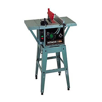
Page 1: Table Saw
MODEL C 10RA POWER TOOLS TECHNICAL DATA TABLE SAW C 10RA SERVICE MANUAL LIST No. E922 Jan. 1999 SPECIFICATIONS AND PARTS ARE SUBJECT TO CHANGE FOR IMPROVEMENT... - Page 2 REMARK: Throughout this TECHNICAL DATA AND SERVICE MANUAL, a symbol(s) is(are) used in the place of company name(s) and model name(s) of our competitor(s). The symbol(s) utilized here is(are) as follows: Competitor Symbol Utilized Company Name Model Name 2708DW MAKITA...
-
Page 3: Table Of Contents
CONTENTS Page [ Business Section ] 1. PRODUCT NAME • • • • • • • • • • • • • • • • • • • • • • • • • • • • • • • • • • • • • • • • • • • • • • • • • • • • • • • • • • • • • • • • • • • • • • • • • • • • • • • • • • • • • • • • • • • • • • • • • • • • • • • • • • • • • • • • • • • • • • 2. - Page 4 [ Appendix ] Assembly Diagram for C 10RA • • • • • • • • • • • • • • • • • • • • • • • • • • • • • • • • • • • • • • • • • • • • • • • • • • • • • • • • • • • • • • • • • • • • • • • • • • • • • • • • • • • • • • • • • • • • • • • • • • • • • • • • • •...
-
Page 5: Product Name
TCT saw blade (36 teeth) is included as a standard accessory. Also, the table saw has a convenient brake (115 V) for faster completion of repeated cutting jobs. The Model C 10RA has many features and specifications that rank it among the top of this class of table saw. -
Page 6: Selling Point Descriptions
Table 3 (4) Equipped with a high-power 2.6 HP motor Maker/Model name Max. output The high-power motor facilitates fast cutting operations. Hitachi C 10RA 60 x 150 mm material 15 seconds HITACHI C 10RA 1,940 W (2.6 HP) 55 x 150 mm material 20 seconds 1,500 W (2.0 HP) -
Page 7: Specifications
5. SPECIFICATIONS 5-1. Specifications Item Specifications Cutting angle 45 bevel Saw blade Max. cutting depth Outer diameter 0 --- 76 mm * 11 --- 63 mm * 255 mm (10") (0 --- 3") (7/16" --- 2-1/2") Outer dia. 255 mm (10") x Inner dia. 15.9 mm (5/8") x Teeth number 36 Saw blade dimensions Outer dia. -
Page 8: Outside View And External Dimensions
5-2. Outside View and External Dimensions (1) Specifications for the U.S.A., Australia and New Zealand models Overall depth 750 mm (29-17/32") Overall height 410 mm (16-1/8") Table depth 500 mm (19-11/16") Table height 310 mm (12-3/16") 455 mm (17-29/32") Dia. 8 mm (5/16") x 4 (pcs.) Mounting hole diameter Mounting hole pitch 395 mm (15-9/16") -
Page 9: Comparisons With Similar Products
6. COMPARISONS WITH SIMILAR PRODUCTS Maker HITACHI Model C 10RA Item 255 mm (10") 210 mm (8-1/4") Outer diameter Saw blade 15.8 mm (5/8"), 25.4 mm (1"), Inner diameter 15.8 mm (5/8") 30 mm (1-3/16") 0 (right angle) 76 mm * (3") -
Page 10: Precautions In Sales Promotion
7. PRECAUTIONS IN SALES PROMOTION In the interest of promoting the safest and most efficient use of the Model C 10RA Table Saw by all of our customers, it is very important that at the time of sale, the salesperson carefully ensures that the buyer seriously recognizes the importance of the contents of the Instruction Manual, and fully understands the meaning of the precautions listed on the various caution plates attached to each machine. -
Page 11: Warning Label (B)
(1) Be sure to wear the protective glasses. (2) Advise the user to use the saw blade guard and spreader when using the table saw. The saw blade guard prevents the operator from touching the saw blade and the dislodging of workpiece. This should be employed to ensure safety. -
Page 12: Package
7-5. Package The Model C 10RA Table Saw is divided into the main table and the extension wing sections before packing and shipping. Therefore, buyers of this machine are required to perform some light assembly. Instruct customers to carefully read the assembly procedure in the Instruction Manual. -
Page 13: Precautions On Operation
8. PRECAUTIONS ON OPERATION 8-1. Unpacking The parts illustrated in Fig. 6 are packaged together with. When unpacking, carefully confirm that all parts are accounted for. 24 25 26 Fig. 6 1. Miter Gauge (1 piece) 14. 6 mm Spring Washer (2 pieces) 2. -
Page 14: Assembly
8-2. Assembly WARNING: To avoid an accident or personal injury, always confirm that the switch is turned OFF and the power plug has been disconnected from the receptacle before assembly of this tool. 8-2-1. Assembly of the Handle The handle allows faster turning of the wheel. When properly assembled, it will rotate freely but with only a small amount of play, (1) Tighten the screw of the handle until it hits against the... - Page 15 8-2-4. Mounting and Adjusting the Saw Blade Guard Assembly (for the U.S.A., Australia and New Zealand) Saw blade CAUTION: The saw blade guard and spreader assembly must be aligned properly to the saw blade in order to prevent kickback. Down Loosen Mount the saw blade guard assembly, which includes the spreader and anti-kickback pawls (see Fig 10-d).
- Page 16 8-2-5. Mounting and Adjusting the Saw Blade Guard (for Europe) Saw blade CAUTION: The saw blade guard and splitter must be aligned properly to the saw blade in order to Down prevent kickback. Loosen (1) Mounting the splitter 1 Turn the wheel fully clockwise and set the saw blade to the Wheel Tighten Tilt lock handle...
- Page 17 8-2-6. Mounting the Table Insert 5 mm Machine screws Table The table insert is mounted to the table with two 5 mm machine Table insert screws. (For the U.S.A., Australia and New Zealand) The table insert is mounted to the table with two 5 mm flat hd. screws.
- Page 18 (5) (For the U.S.A.) Apply the scale to the extension wings (See Fig. 14-c). 2" Before sticking on the scales to the right and left extension wing ledges, carefully mark a reference line with a pencil on each extension wing: Extension wing Scale Scale ledge...
-
Page 19: Adjustment
8-3. Adjustment The tool is accurately adjusted before shipping from the factory. Check the following settings and readjust them if necessary in order to obtain the best results in operation. WARNING: To avoid an accident or personal injury, always confirm that the switch is turned OFF and the power plug has been disconnected from the receptacle before adjustment of this tool. - Page 20 8-3-2. Adjusting the 90 and 45 Positive Stops The tool is equipped with positive stops for rapid and accurate Saw blade positioning of the saw blade at 90 and left bevel 45 to the table. Down Check and adjust the positive stops with the following Loosen procedures.
- Page 21 8-3-3. Adjustment of the Rip Fence (Fence Ass'y) Before shipment from the factory the saw blade is set parallel to Rip fence the miter-gauge groove and the rip fence is adjusted parallel to the miter-gauge groove. Check and adjust the parallelism of the rip fence with the following procedures in order to assure accuracy and prevent kickback when ripping.
- Page 22 8-3-4. Adjustment of the Pointer The pointer indicates the distance the rip fence is positioned away from the saw blade. The pointer should indicate the accurate distance from the saw blade. Check and adjust the pointer with the following procedures. NOTE: The pointer will need to be readjusted whenever a different thickness saw blade is installed.
-
Page 23: Relation Between Saw Blade And Spreader (Or Splitter)
OFF, the rotation usually stops in 3 to 5 seconds. Should it take more than 15 seconds before stopping, the machine should not be used. Instruct the customer to contact a Hitachi electric tool dealer for inspection or repair if this occurs. -
Page 24: Extension Cords
8-7. Extension Cords The Instruction Manual contains a table of cord lengths and lead wire diameters. Select an appropriate extension cord. If the lead wire diameter is too small compared with the cord length, it may cause considerable voltage drops, resulting in lowered efficiency. Use only three-wire extension cords which have three-prong grounding-type plugs and three-pole receptacles which accept the saw's plug. -
Page 25: Cutting Work
8-8. Cutting Work Precautions on cutting work are provided in the Instruction Manual. Read them carefully and advise the user on correct operation. In this section, important items and the items not described in the Instruction Manual are explained to help you advise the user. (1) For cutting work, be sure to use the saw blade guard and check that everything functions properly. -
Page 26: Maintenance And Inspection
9. MAINTENANCE AND INSPECTION WARNING: To avoid an accident or personal injury, always confirm that the switch is turned OFF and that the power plug has been disconnected from the receptacle before performing any maintenance or inspection of this tool. 9-1. -
Page 27: Inspecting The Saw Blade Guard For Proper Operation
9-4. Inspecting the Saw Blade Guard for Proper Operation Before each use of the tool, test the saw blade guard to assure that it is in good condition and that it moves smoothly. Never use the tool unless the saw blade guard operates properly and unless it is in good mechanical condition. -
Page 28: Precautions In Disassembly And Reassembly
10. PRECAUTIONS IN DISASSEMBLY AND REASSEMBLY Please follow the precautions below for disassembly and reassembly procedures. The circled numbers in the following figures and the [Bold] numbers in the descriptions below correspond to the item numbers in the Parts List and exploded assembly diagrams. CAUTION: Prior to attempting disassembly or replacement of the saw blade, ensure that the power cord plug is disconnected from the power source. - Page 29 (1) Remove the M6 x 60 Bolt [14] and M6 x 35 Bolt [21] using a 10 mm wrench, and remove the Saw Blade Guard and Spreader Assembly (Blade Guard [7] and Spreader [23]). (For the U.S.A., Australia and New Zealand) Remove the M6 x 16 Bolt [174] with the hex.
- Page 30 (2) Remove the three D4 x 10 Tapping Screws [111] and remove the Switch Box [109]. Then, remove the two D4 x 10 Tapping Screws (Special) [119] and detach the ground wire (green/yellow). C. Disassembly of the motor and wheel sections Tools required: •...
- Page 31 (1) Turn the Wheel [126] counterclockwise and move the motor to the lower limit position. Turn the Tension Handle [125] counterclockwise to loosen and tilt the motor at an angle of 45 degrees. Turn the Tension handle [125] clockwise to tighten. Then, turn the body (Table [33] surface upside down.) (2) Remove the two Brush Caps [220] and remove the two Carbon Brushes [221].
- Page 32 D. Disassembly of the body and spindle sections Tools required: • Pillips head screwdriver • 3 mm hexagon bar wrench • 8 mm, 10 mm and 13 mm wrenches • Plastic hammer Fig. 28 (1) Remove the four M6 Nuts [82] using a 10 mm wrench, and remove the Body [70] from the Table [33]. (2) Remove the four M6 x 12 Machine Screws [84], and remove the Bracket [85].
- Page 33 (8) Remove the four M4 x 12 machine Screws [203], and remove the Bearing Retainer [205]. (9) Remove the Spindle Ass'y [201] by striking the Bracket [211] with a plastic hammer. (10) Hold the Screw Bar [68] using an 8 mm wrench, and remove the M8 Nut Chuck [69] with a 13 mm wrench. Remove the Screw Bar [68] from the Bracket [211].
- Page 34 Motor Parts Fig. 30 --- 30 ---...
-
Page 35: Reassembly
10-2. Reassembly Perform reassembly in reverse order of disassembly while observing the following precautions. (1) Prior to reassembly, measure the insulation resistance of the armature ass'y, stator ass'y, switch and other electrical components with a DC 500 V Megohm Tester, and confirm that the insulation resistance of each part is more than 5 M . -
Page 36: Wiring
Mount the slide plate with the 8.5 mm side facing the motor. Motor Fig. 31 10-3. Wiring Wiring should be performed as shown in Fig. 32., Fig. 33, Fig. 34, Fig. 35. Please note that incorrect wiring will result in a failure in rotation. (1) Wiring diagram 1 110 V Lead... - Page 37 2 115 V Rocker Lead Circuit switch wire breaker (black) Motor switch Black Power Black cable Stator cable core outer Armature circumference ass'y White White Break coil Green (ground) Green (ground) Stator coil Stator ass'y Fig. 33 3 230 V Lead Lead wire...
- Page 38 (2) Lead wire arrangements 1 110 V Faston Blue terminal Motor Circuit cable breaker Brown switch Brown Green/yellow Brown (ground) White Brown NVR- Blue switch Brown Blue Blue Power Green/yellow cable (ground) Fig. 36 2 115 V Blue Circuit breaker Motor Black switch...
- Page 39 3 230 V Green/yellow Faston (ground) terminal Blue Motor Circuit cable breaker Brown switch Brown Green/yellow Brown (ground) White Brown NVR- Blue switch Brown Blue Blue Power Green/yellow cable (ground) Fig. 38 4 240 V Green/yellow (ground) Faston terminal Blue Motor Circuit cable...
-
Page 40: Adjustments
10-4. Adjustments After disassembly and reassembly, the following parts require adjustment. After being disassembled and reassembled, the affected items should be adjusted. For adjustment, see the adjusting method described in 8-3. Adjustment on page 15. (1) Parallel alignment of the saw blade and the miter-gauge groove (2) Saw blade squareness and tilting 45 stopper position (3) Parallel alignment of the rip fence and the miter-gauge groove (4) Pointer position of the rip fence... -
Page 41: Repair Guide
11. REPAIR GUIDE Factory rated Remedy Problem Possible cause value 0.4/60 • Readjust the squareness of the Low cutting accuracy a) Because of poor (Dummy disc) saw blade using the M6 x 20 squareness between --- poor squareness of (Fig. 40) Seal Lock Screw [27]. - Page 42 Excessive force is applied because of a • Replace the Saw Blade [704]. dull saw blade. ------ • Use a genuine Hitachi saw d) Wrong selection of saw blade. blade. • The higher the number of teeth of a saw blade, the more cutting resistance increases.
- Page 43 Factory rated Remedy Problem Possible cause value ------ a) Power cord is not • Check the power voltage. The saw blade won't • Plug the power cord into the connected to the turn even if the switch outlet. power outlet. is turned on.
-
Page 44: Standard Repair Time (Unit) Schedules
12. STANDARD REPAIR TIME (UNIT) SCHEDULES Variable MODEL 70 min. Fixed Wark Flow C 10RA Extension Wing (L) Extension Wirg (R) General Assembly Circuit Breaker Switch Box Switch Blade Guard Switch MTG. Spreader Plate 0 min. (Splitter) Rocker Switch Switch MTG. -
Page 45: Assembly Diagram For C 10Ra
Assembly Diagram for C 10RA --- 41 ---... - Page 46 Assembly Diagram for C 10RA --- 42 ---...
- Page 47 Assembly Diagram for C 10RA --- 43 ---...
- Page 48 C 10RA PARTS ITEM CODE NO. DESCRIPTION REMARKS USED 314-473 FLAT WASHER M6 FOR USA,AUS,NZL 314-473 FLAT WASHER M6 FOR GBR,FRG,BEL,ITA 314-474 NUT CHUCK M6 FOR USA,AUS,NZL 949-644 BOLT M6X40 (10 PCS.) FOR USA,AUS,NZL 314-476 SELF-LOCKING RING FOR USA,AUS,NZL 314-477...
- Page 49 C 10RA PARTS ITEM CODE NO. DESCRIPTION REMARKS USED 314-502 FRONT CLAMP 314-503 CLAMP HANDLE (A) 314-504 POINTER 949-431 BOLT WASHER M5 (10 PCS.) 949-234 MACHINE SCREW M5X6 (10 PCS.) 314-505 CLAMP HANDLE (B) 314-506 FLAT WASHER M6.4 314-507 MITER GAUGE 949-234 MACHINE SCREW M5X6 (10 PCS.)
- Page 50 C 10RA PARTS ITEM CODE NO. DESCRIPTION REMARKS USED 314-538 REGULATING BOLT 949-518 ROLL PIN D3X18 (10 PCS.) 973-361 WASHER 996-577 BOLT (W/WASHERS) M6X12 (BLACK) 314-539 BODY SHELL FOR USA,AUS,NZL 317-157 BODY SHELL FOR GBR,FRG,BEL,ITA WARNING LABEL (B) WARNING LABEL (A)
- Page 51 C 10RA PARTS ITEM CODE NO. DESCRIPTION REMARKS USED 949-455 SPRING WASHER M6 (10 PCS.) 949-455 SPRING WASHER M6 (10 PCS.) 949-455 SPRING WASHER M6 (10 PCS.) 949-455 SPRING WASHER M6 (10 PCS.) 315-040 BLADE GUARD ASS’Y INCLUD.1-18,21-25,136 FOR USA,AUS,NZL 315-041 FENCE ASS’Y...
-
Page 52: Standard Accessories
C 10RA PARTS ITEM CODE NO. DESCRIPTION REMARKS USED 314-453 STATOR 115V 317-137 STATOR 230V 317-138 STATOR 240V 314-577 BEARING BUSHING 314-583 BRUSH CAP 999-044 CARBON BRUSH (1 PAIR) 314-585 HOUSING ASS’Y INCLUD.223,226 314-586 BRUSH HOLDER 949-454 SPRING WASHER M5 (10 PCS.) 949-245 MACHINE SCREW M5X30 (10 PCS.)
Need help?
Do you have a question about the C 10RA and is the answer not in the manual?
Questions and answers