Table of Contents
Advertisement
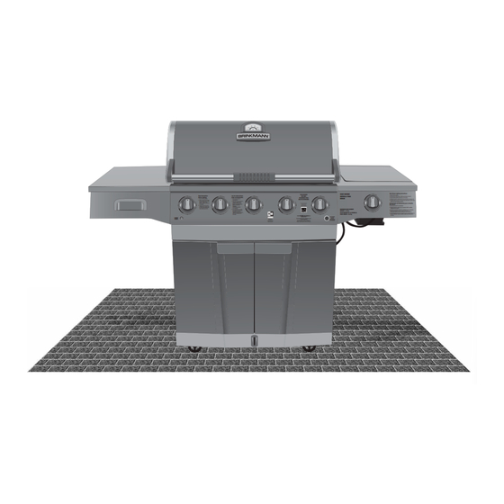
Parrilla de Gas de Alta Resistencia
OWNER'S MANUAL / MANUAL DEL PROPIETARIO
GUARDE ESTE MANUAL PARA REFERENCIA FUTURA
NOTICE TO INSTALLER:
LEAVE THESE INSTRUCTIONS
WITH THE GRILL OWNER FOR
FUTURE REFERENCE .
AVISO PARA EL
INSTALADOR:
ENTREGUE ESTAS
INSTRUCCIONES AL
PROPIETARIO DE LA PARRILLA
PARA REFERENCIA FUTURA.
Heavy-Duty Gas Grill
ASSEMBLY AND OPERATING IN STRUC TIONS
INSTRUCCIONES DE ARMADO Y OPERACIÓN
SAVE THIS MANUAL FOR FUTURE REFERENCE
HAZARDOUS EXPLOSION MAY RESULT IF THESE WARNINGS AND INSTRUCTIONS
ARE IGNORED. READ AND FOLLOW ALL WARNINGS AND INSTRUCTIONS IN THIS
MANUAL TO AVOID PERSONAL INJURY, INCLUDING DEATH OR PROPERTY DAMAGE.
SE PUEDE PRODUCIR UNA EXPLOSIÓN PELIGROSA SI SE HACE CASO OMISO A
ESTAS ADVERTENCIAS E INSTRUCCIONES. LEA Y SIGA TODAS LAS ADVERTENCIAS
E INSTRUCCIONES EN ESTE MANUAL PARA EVITAR LESIONES PERSONALES,
Read Instructions
Before Lighting:
1. Open lid during lighting.
2. Select a burner to be lit. Push
and turn control knob of that
burner to "HIGH." Press
electronic igniter and hold for
3-5 seconds.
3. If ignition does not occur in
5 seconds, turn control knob
to "OFF," wait 5 minutes and
repeat lighting procedure.
LIGHTS
LUCES
WARNING/ADVERTENCIA
INCLUSO LA MUERTE, O LOS DA—OS MATERIALES.
300
400
200
500
100
600
FOR OUTDOOR
Lea las Instrucciones
USE ONLY
Antes de Iluminación:
SOLAMENTE PARA
1. Abra la tapa durante el
USO EN EXTERIORES
encendimiento.
2. Seleccione la hornilla que va a
encender. Empuje y gire la
perilla de control de esa
Scan with a Smart Phone
hornilla a la posición "ALTO".
for More Information
Oprima el encendedor
Escanear con un
Teléfono Inteligente
electrónico
para Más Información
y manténgalo oprimido
3 a 5 segundos.
3. Si la hornilla NO se enciende
en 5 segundos, gire la perilla
de control a la posición
"APAGADO"espere 5 minutos y
repita el procedimiento de
encendido.
800-527-0717
For Accessories, Parts or Assistance, Call
NG Conversion
or Visit our Website
Kit Required
Para Accesorios, Partes o Asistencia,
Kit de la Conversión
Llame o Visite Nuestro Sitio de Internet
del NG Requerido
Sear Burner Lighting Instructions:
SEAR BURNER
1. Open lid during lighting.
HORNILLA PARA
2. Push and turn control knob to "HIGH" and continue to push in.
3. Press electronic igniter and hold for 3 to 5 seconds.
DORAR
4. Continue to push in control knob for 30 seconds after sear burner is lit.
5. If ignition does not occur in 5 seconds, turn control knob to "OFF," wait 5
minutes and repeat lighting procedure.
Instrucciones de Iluminación para la Hornilla
para Dorar:
1. Abra la tapa durante el encendimiento.
2. Empuje la perilla de control y gire a la posición "ALTO" y continúe
empujando hacia adentro.
MAXIMUM SEAR BURNER
3. Presione el encendedor electrónico y sosténgase por 3 a 5 segundos.
WEIGHT = 15 lbs.
4. Continúe empujando la perilla de control hacia adentro por
30 segundos después de que la hornilla para dorar se enciende.
PESO MÁXIMO DE LA HORNILLA
5. Si la hornilla NO se enciende en 5 segundos, gire la perilla de control a la
PARA DORAR = 6.8 kg
posición "APAGADO", espere 5 minutos y repita el procedimiento de
encendido.
ELECTRONIC
IGNITER
ENCENDEDOR
ELECTRÓNICO
Advertisement
Table of Contents

Subscribe to Our Youtube Channel
Related Manuals for Brinkmann Heavy-Duty Gas Grill


Summary of Contents for Brinkmann Heavy-Duty Gas Grill
- Page 1 Heavy-Duty Gas Grill Parrilla de Gas de Alta Resistencia OWNER’S MANUAL / MANUAL DEL PROPIETARIO ASSEMBLY AND OPERATING IN STRUC TIONS INSTRUCCIONES DE ARMADO Y OPERACIÓN SAVE THIS MANUAL FOR FUTURE REFERENCE GUARDE ESTE MANUAL PARA REFERENCIA FUTURA WARNING/ADVERTENCIA NOTICE TO INSTALLER:...
- Page 2 IMPORTANT SAFETY WARNINGS WE WANT YOU TO ASSEMBLE AND USE YOUR GRILL AS SAFELY AS POSSIBLE. THE PURPOSE OF THIS SAFETY ALERT SYMBOL IS TO ATTRACT YOUR ATTENTION TO POSSIBLE HAZARDS AS YOU ASSEMBLE AND USE YOUR GRILL. WHEN YOU SEE THE SAFETY ALERT SYMBOL PAY CLOSE ATTENTION TO THE INFORMATION WHICH FOLLOWS! READ ALL SAFETY WARNINGS AND INSTRUCTIONS CAREFULLY BEFORE ASSEMBLING AND OPERATING YOUR GRILL.
-
Page 3: Table Of Contents
TABLE OF CONTENTS: General Warnings ..........3-4 LP Gas Cylinder (Tank) Specifi cations and Installation . -
Page 4: General Warnings
GENERAL WARNINGS: WARNING • Leak test all connections before fi rst use, even if grill was purchased fully assembled and after each tank refi ll. Check the propane tank rubber seal for damage. • Always check the grill and propane tank prior to each use as indicated in the “Checking for Leaks”... -
Page 5: Lp Gas Cylinder (Tank) Specifications And Installation
• Grill is hot when in use. To avoid burns: • DO NOT attempt to move the grill. • Block the wheels so the unit does not accidentally move. • Wear protective gloves or oven mitts. • DO NOT touch any hot grill surfaces. •... - Page 6 LP GAS CYLINDER (TANK) SPECIFICATIONS: LP gas cylinder (not supplied with this grill) The LP (Liquid Propane) gas cylinder specifi cally designed to be used with this grill must be 12” (30.5 cm) diameter x 18” (45.7 cm) tall and have a 20 lb. (9.1 kg) capacity incorporating a Type 1 cylinder valve and an over-fi lling protection device (OPD).
-
Page 7: Hose & Regulator Specifications And Installation
LP GAS CYLINDER (TANK) RUBBER SEAL INSPECTION: • Inspect the propane tank valve rubber seal for cracks, wear or deterioration prior to use. A damaged rubber seal can cause a gas leak, possibly resulting in an explosion, fi re or severe bodily harm. •... -
Page 8: Leak Testing
HOSE AND REGULATOR: Your grill is equipped with a Type 1 connection device with the following features: 1. The system will not allow gas fl ow from the cylinder until a positive connection to the valve has been made. Note: The cylinder valve and all grill burner knobs must be turned OFF before any connection is made or removed. -
Page 9: Checking For Leaks
DANGER To prevent fi re or explosion hazard: • DO NOT smoke or permit ignition sources in the area while conducting a leak test. • Perform test OUTDOORS in a well ventilated area that is protected from the wind. • Never perform a leak test with a match or open fl ame. -
Page 10: Pre-Start Check List
PRE-START CHECK LIST: DANGER Property damage, bodily harm, severe burns, and death could result from failure to follow these safety steps. These steps should be performed after the grill has been assembled and prior to each use. DO NOT operate this grill until you have read and understand ALL of the warnings and instructions in this manual. -
Page 11: Lighting Instructions
6. Repeat steps 3–5 for lighting each burner. Always use electronic igniter for lighting each burner. If burner does not ignite using the push-button igniter, wait 5 minutes, see “Match Lighting the Main Burners” section. To turn off, turn each control knob clockwise until it locks in the “OFF” position. This does not turn off the gas fl ow from the cylinder.. -
Page 12: Operating The Grill
OPERATING THE GRILL: WARNING • Read and follow all warnings and instructions contained in the preceding sections of this manual. • Never use charcoal, lava rocks or wood briquets in a gas grill. Flavoring chips must be contained in a metal smoking box to contain ash and prevent fi res. •... -
Page 13: Rotisserie Cooking
ROTISSERIE COOKING: • Your grill was pre-drilled from factory to include mounting holes for a rotisserie (sold separately). Do not use a rotisserie not specifi cally manufactured for this grill. • Read and follow all instructions provided with the rotisserie. Save instructions for future reference. •... -
Page 14: Proper Care And Maintenance
PROPER CARE & MAINTENANCE: WARNING: If a bristle brush is used to clean any of the cooking surfaces, ensure no loose bristles remain on the cooking surfaces prior to grilling as loose bristles may attach to food. CLEANING INTERIOR OF GRILL: •... -
Page 15: Burner Assembly/Maintenance
BURNER ASSEMBLY/MAINTENANCE: • Although your burners are constructed of stainless steel, they may corrode as a result of the extreme heat and acids from cooking foods. Regularly inspect the burners for cracks, abnormal holes, and other signs of corrosion damage. If found, replace the burner. -
Page 16: Transporting And Storage
BURNER ADJUSTMENT: WARNING • DO NOT attempt to adjust burner air shutter until grill has cooled down for approximately 30 minutes. Failure to do so could cause severe burns. • Normal fl ame should be soft blue with yellow tips between 1 in. - 2 in. when burner is on “HIGH” . Depending on elevation, burner air shutter may need to be adjusted to obtain correct air to fuel ratio. -
Page 17: Trouble Shooting
TROUBLE SHOOTING: To see trouble shooting or assembly videos, visit us at: Problem Possible Cause Prevention/Cure Burner will not light LP gas tank valve is closed Make sure regulator is securely attached to the LP gas tank, turn LP gas tank valve to “OPEN” LP gas tank is low or empty Check if LP gas tank is empty. -
Page 18: Grill Cooking Tips
Problem Possible Cause Prevention/Cure Flame blows out High or gusting winds Do not use grill in high winds Low on LP gas Replace or refi ll LP gas tank Burner holes may be obstructed Refer to “Burner Assembly/Maintenance” instructions Flow limiting device tripped Refer to “Regulator Resetting Procedure”... -
Page 19: Assembly Instructions
ASSEMBLY INSTRUCTIONS: Make sure you have all items listed under PARTS LIST and PARTS BAG CONTENTS before you begin the installation process. PARTS BAG CONTAINS: Qty. Qty. M6 X 12 mm Bolts (Black) Locking Nut 17 M6 X 12 mm Bolts (Silver) M6 Washers M6 X 30 mm Bolts (Silver) Hinge Pins... -
Page 20: Parts List & View
READ ALL SAFETY WARNINGS & ASSEMBLY INSTRUCTIONS CAREFULLY BEFORE ASSEMBLING OR OPERATING YOUR GRILL. WE RECOMMEND TWO PEOPLE WORK TOGETHER WHEN AS SEM BLING THIS UNIT. The following tools are required to assemble this Brinkmann Heavy-Duty Gas Grill: • Screwdriver • Hex Nut Wrench... - Page 21 FOR COVERS, ACCESSORIES AND OTHER PRODUCTS, PLEASE VISIT US ONLINE AT: (Proof of purchase will be required.) Inspect contents of the box to ensure all parts are included and undamaged.
- Page 22 Choose a good, cleared assembly area and get a friend to help you put your grill together. Lay card board down to protect grill fi nish and assembly area. CAUTION: Some parts may contain sharp edges. Wear protective gloves if necessary. Step 1 Lower Cart Brace Turn cart base upside down, use...
- Page 23 Figure 1 Step 3 Tank Gauge Bracket Remove the spring, washer, and bolt from the tank gauge bracket. Set aside for use in Step 5. Attach the tank gauge bracket onto the base using two M6 X 12 mm bolts (sliver) as illustrated in Figure 1.
- Page 24 Right Panel Left Panel Step 6 Using four M6 X12 mm bolts (silver) attach the left panel and the right panel to the cart base. Step 7 Using four M6 X 12 mm bolts (silver) attach the back panel. Back Panel...
- Page 25 Step 8 M6 X 12 mm To attach the wind defl ector, insert the upper cart brace pre-attached bolts through the key holes of the wind defl ector, slide the wind defl ector downward and tighten the bolts securely. See Figure 1 and 2 below.
- Page 26 Grill Body Assembly Step 10 With the help of a friend, place the grill body assembly on the grill cart. Secure using four M6 X 12 mm bolts (black) from the left and the right side of the frame. Fixed Stands Left Side Table Assembly Step 11 To attach the left side table...
- Page 27 Figure 1 Figure 2 Step 12 Right Side Table Assembly To attach the right side table assembly, fi rst insert the side table’s fi xed stands onto the grill body hooks (Figure 1). M5 X 12 mm Open the grill hood, then use one M5 X 12 mm bolts (black) and one M6 washer to secure the right side table assembly to the grill body from...
- Page 28 Step 14 Remove the retaining nut from the Thermocouple top of the thermocouple, and insert the thermocouple into the hole in the sear burner as shown. Reattach Sear Burner nut on the other side and tighten. Igniter Lead Retaining nut Remove the pre-attached screws from the sear burner.
- Page 29 Sear Burner Grate Step 16 Slide open the right side table, insert the sear burner grate. Open Warming Rack Cooking Grills Step 17 Place the heat tents on lower level of grill body assembly directly above burners. Heat Tents Step 18 Place cooking grills on support ribs directly above heat tents.
- Page 30 Step 20 Insert the sear Burner grease tray on the tracks under sear burner in back. Sear Burner Grease Tray Figure 1 Step 21 Attach the tank heat shield under Grease Tray the grease tray using two M4 X 12 mm bolts (black) (Figure 1).
- Page 31 Step 22 Hang grease cup from the grease tray. Make sure to slide cup onto tracks as illustrated. Grease Cup ® Brinkmann 4580 (Assembled) Sear Burner Lighting Instructions: SEAR BURNER FOR OUTDOOR 1. Open lid during lighting. Read Instructions Lea las Instrucciones...
- Page 32 PARA CUBIERTAS, ACCESORIOS Y OTROS PRODUCTOS, FAVOR DE VISITARNOS POR LA RED MUNDIAL EN: WARRANTY The Brinkmann Corporation warrants to the original pur chas er that the Brinkmann Heavy-Duty Gas Grill is free from defects due to workmanship or materials for:...
Need help?
Do you have a question about the Heavy-Duty Gas Grill and is the answer not in the manual?
Questions and answers