
Related Manuals for Midland 91-1060-91-1110


Summary of Contents for Midland 91-1060-91-1110
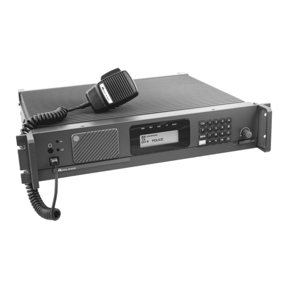
- Page 1 SERVICE MANUAL ADDENDUM P25/FM TWO-WAY LAND MOBILE RADIO BASE TECH III BASE/REPEATER STATION 91-1060-91-1110 91-4050-91-4100 LOW CURRENT MODELS VHF HIGH BAND UHF BAND Part Number: 680-100-2049 Revision A 1/12...
-
Page 2: Important Information
© 2012 Midland Radio Corporation This manual is designed to facilitate the set-up and service of the Midland 91-1060 / 1110 91-4050 / 91-4100 P25 Base Tech III series. As necessary, service manual supplements will be published and distributed on the following forms:... -
Page 3: Table Of Contents
VHF TX Main Unit Layouts UHF RX Main Unit Layouts UHF RX VCO Unit Layout UHF TX Main Unit Layouts Chassis Exploded View Palm Microphone Schematic PARTS Low Current Specific Parts List…………….. 40-56 Replacement Parts Ordering © 2012 Midland Radio Corporation... -
Page 4: Acronyms And Abbreviations
TX --------------------------- Transmit SINAD ---------------------- The ratio in decibels of signal + noise + distortion to noise + distortion VCO ------------------------ Voltage Controlled Oscillator TCXO ---------------------- Temperature Compensated Crystal Oscillator PLL ------------------------- Phase Locked Loop © 2012 Midland Radio Corporation... -
Page 5: General Information
≤ 3% @ 1 kHz 60% mod. AF Distortion: 7.5 Watts @ 8 Ώ/ 10 Watts @ 4 Ώ Audio Output Power: ≥ 50 dB @ 1 kHz 70% mod. (wideband), ≥ 45 dB (narrowband) Signal to Noise Ratio: © 2012 Midland Radio Corporation... - Page 6 ≤ 3% @ 1 kHz 60% mod. AF Distortion: 7.5 Watts @ 8 Ώ/ 10 Watts @ 4 Ώ Audio Output (<2% distortion): ≥ 50 dB @ 1kHz 60% mod. (45 dB at narrow) Signal to Noise Ratio: © 2012 Midland Radio Corporation...
-
Page 7: Accessories
Base Tech III Programming Software 71-2020E 16 Channel Tone Remote Termination 71-2022E E&M Expansion Kit used with 71-2020E in 71-8885A/D Option Shelf (only) 71-8885A Option Shelf with Slides / Easy Access & AC Supply No Battery Charge © 2012 Midland Radio Corporation... - Page 8 VHF Duplexer (2 MHz Separation) 350W, 150-160 71-8152-4 VHF Duplexer (2 MHz Separation) 350W, 160-174 71-8455A UHF Duplexer (3-5 MHz Separation) 350W, 440- 512 MHz 71-8455D UHF Duplexer (3-5 MHz Separation) 350W, 406- 430 MHz © 2012 Midland Radio Corporation...
-
Page 9: Alignment
Alignment Procedures Low Current Base Tech 3.5 THIS PAGE INTENTIONALLY LEFT BLANK © 2012 Midland Radio Corporation... -
Page 10: Alignment Procedures
Cycle power to the radio to return to normal operation. NOTE: The other ADJUST Modes are in order of appearance: RX 0 dbm REPEAT DEVI DIGITAL DEVI ANALOG DEVI TONE DEVI CTC DEVI WID CTC DEVI NRW © 2012 Midland Radio Corporation... - Page 11 Alignment Procedures Low Current Base Tech 3.5 FVR002 De-mod Bias FVR001 Tight Squelch Figure 1: Receive Module (RX Main Unit) Alignment Adjustments © 2012 Midland Radio Corporation...
- Page 12 See Figure 2. Note that tuning slug may be glued and breakage could occur. VCO L303 (under cover) FVR201 Sub-Audible Balance FVR204 TP301) Output Power FVR202 FVR203 Sub-Audible Frequency Trim Deviation Figure 2: Exciter Module (TX Main Unit) Alignment Adjustments © 2012 Midland Radio Corporation...
- Page 13 Changes made during alignment will be automatically stored when entered. h) The following adjustment are available in order of appearance: RX 0 dbm REPEAT DEVI DIGITAL DEVI ANALOG DEVI TONE DEVI CTC DEVI WID CTC DEVI NRW © 2012 Midland Radio Corporation...
- Page 14 Press the “#” key on the Front Panel until second line of the LCD displays “TONE DEVI.” c) Activate PTT. d) Press the “A” key to increase or the “B” key to decrease the CWID transmitter deviation until it is 40% ± 5% system deviation. e) Deactivate PTT. © 2012 Midland Radio Corporation...
- Page 15 Press the number 3 key to transmit the Standard Transmitter Low Deviation Pattern. k) Monitor peak FM deviation. Verify that both positive and negative peak deviation levels each fall within 848 Hz to 1037 Hz deviation. Deactivate PTT. © 2012 Midland Radio Corporation...
-
Page 16: Alignment
Low-Power Mode. Press “SHIFT,” then “2” to toggle transmitter Power Mode. FVR401 VR401 FVR402 High-Power Level Pulse Code Sw itch Low-Power Level Adjustment Function by # of presses: Adjustment Volume Noise Squelch Backlight Dim Backlight Timer © 2012 Midland Radio Corporation... -
Page 17: Circuit Description
An additional 5.5 volt dc source has replaced the 12 V dc source for main on board power. An additional 12 volt line has been added for the 7 V dc regulator. This significantly reduces current consumption losses to heat. © 2012 Midland Radio Corporation... - Page 18 An APC circuit formed by IC502, IC503, Q504 and Q505 stabilizes the output power at the set level. IC501 protects PM501 from the reverse power caused by a mismatched antenna system © 2012 Midland Radio Corporation...
- Page 19 IC1 acts as the DSP control for both incoming digital signal converting it to analog and analog signal to C4FM digital signal. External flash memory within IC2, has 4Mb capacity, contains all data. Program data is stored in 256 k-bytes of memory integrated within IC1. © 2012 Midland Radio Corporation...
- Page 20 3) Audio Amplifier Section IC402 has up to 10 W power into a 4Ω impedance speaker. 4) Microphone Pre-Amplifier Section IC411 is the voice pre-amplifier having –30dBm output to feed TX modulator. Front panel microphone impedance is 600Ω. © 2012 Midland Radio Corporation...
-
Page 21: Description
Buffered receive audio ≈700mVrms 1KHz @ ±3KHz 600 ohm input TX OUT EXT PW/SW External power switch 0-Open source 0V=ONf REMOTE External channel selection mode 0-+3.3VDC 0V=external +12V Pin 13 Pin 1 Pin 25 Pin 14 © 2012 Midland Radio Corporation... - Page 22 Circuit Description Low Current Base Tech 3.5 Notes: © 2012 Midland Radio Corporation...
-
Page 23: Vhf/ Uhf General Block Diagrams
Block Diagram VHF 60 Watt Low Current Base Tech 3.5 © 2012 Midland Radio Corporation... - Page 24 Block Diagram VHF 110 Watt Low Current Base Tech 3.5 © 2012 Midland Radio Corporation...
- Page 25 Block Diagram UHF 50 Watt Low Current Base Tech 3.5 © 2012 Midland Radio Corporation...
- Page 26 Block Diagram UHF 100 Watt Low Current Base Tech 3.5 © 2012 Midland Radio Corporation...
-
Page 27: Front Panel Unit Schematic
Front Panel Unit Schematic Low Current Base Tech 3.5 © 2012 Midland Radio Corporation... -
Page 28: Analog Logic Unit Schematic
Analog Logic Unit Schematic Low Current Base Tech 3.5 © 2012 Midland Radio Corporation... -
Page 29: Vhf Rx Main Unit Schematic
VHF RX Main Unit Schematic Low Current Base Tech 3.5 © 2012 Midland Radio Corporation... -
Page 30: Vhf Rx Vco Unit Schematic
VHF RX VCO Unit Schematic Low Current Base Tech 3.5 © 2012 Midland Radio Corporation... -
Page 31: Vhf Tx Main Unit Schematic
VHF TX Main Unit Schematic Low Current Base Tech 3.5 © 2012 Midland Radio Corporation... -
Page 32: Uhf Rx Main Unit Schematic
UHF RX Main Unit Schematic Low Current Base Tech 3.5 © 2012 Midland Radio Corporation... -
Page 33: Uhf Rx Vco Unit Schematic
UHF RX VCO Unit Schematic Low Current Base Tech 3.5 © 2012 Midland Radio Corporation... -
Page 34: Uhf Tx Main Unit Schematic
UHF TX Main Unit Schematic Low Current Base Tech 3.5 © 2012 Midland Radio Corporation... -
Page 35: Front Panel Unit Layout
Front Panel Unit Layouts Low Current Base Tech 3.5 © 2012 Midland Radio Corporation... -
Page 36: Analog Logic Unit Layout
Analog Logic Unit Layouts Low Current Base Tech 3.5 © 2012 Midland Radio Corporation... -
Page 37: Vhf Rx Main Unit Layouts
VHF RX Main Unit & RX VCO Unit Layouts Low Current Base Tech 3.5 RX Main Unit Top Side RX Main Unit Bottom Side RX VCO Unit Top Side RX VCO Unit Bottom Side © 2012 Midland Radio Corporation... -
Page 38: Vhf Tx Main Unit Layouts
VHF TX Main Unit Layouts Low Current Base Tech 3.5 TX Main Unit Top Side TX Main Unit Bottom Side © 2012 Midland Radio Corporation... -
Page 39: Uhf Rx Main Unit Layouts
UHF RX Main Unit & RX VCO Unit Layouts Low current Base Tech 3.5 RX Main Unit Top Side RX Main Unit Bottom Side RX VCO Unit Top Side RX VCO Unit Bottom Side © 2012 Midland Radio Corporation... -
Page 40: Uhf Tx Main Unit Layouts
UHF TX Main Unit Layouts Low Current Base Tech 3.5 TX Unit Top Side TX Unit Bottom Side © 2012 Midland Radio Corporation... -
Page 41: Chassis Exploded View
17. Screw (3 x 8 mm) 18. Screw (4 x 8 mm) 19. Screw (4 x 10 mm) 20. Screw (4 x 12 mm) 21. Screw (4 x 6 mm) 22. Screw #4-40 Jack 23. Hex Standoff (3 x 8 © 2012 Midland Radio Corporation... - Page 42 THIS PAGE INTENTIONALLY LEFT BLANK © 2012 Midland Radio Corporation...
-
Page 43: Palm Microphone Schematic
Palm Microphone Schematic Low Current Base Tech 3.5 © 2012 Midland Radio Corporation... -
Page 44: Low Current Specific Parts List
RX Main Unit Assembly, UHF “A” Range (400-430 MHz) 650-110-2016 RX Main Unit Assembly, UHF “B” Range (440-475 MHz) 650-110-2017 RX Main Unit Assembly, UHF “C” Range (465-500 MHz) 650-110-2018 RX Main Unit Assembly, UHF “D” Range (485-520 MHz) 650-110-2019 © 2012 Midland Radio Corporation... - Page 45 R472, R484 EMVE500ADA2R2MD55G C407 MCR03EZHJ 153 R478, R480 GRM188B11H471KD01D C408 MCR03EZHJ 274 R486 GRM21BB11A105KA01L C409, C414, C416, C419, C420 GF06P 10K FVR401 GRM188B11C473KA01D C410 GF06P 100K FVR402 EKMG350ELL471MJ16S C411, C412 ERTJR103J TH401 GRM188B11H562KD01D C413 GRM21BB31A475KA74L C415 © 2012 Midland Radio Corporation...
- Page 46 IC14 GRM188B11E104KA01D C6, C9, C13, C14, C19, C29, BU4SU69 IC15 C33, C36, C43, C45, C58, C61, BU4S01G2-TR IC16 C63, C64, C70, C112, C113, C116 BU4S81G-TR IC17, IC25 GRM21BB31A475KA74L C7, C8 NJM2073M(TE1) IC18 DP7113 IC22, IC23 © 2012 Midland Radio Corporation...
- Page 47 MCR03EZHJ 753 RA12, RA13, RA14, MCR03EZHJ 103 R14, R15, R17, R20, R21, R30, MNR14E0ABJ473 RA10, RA15, RA16 R31, R35, R63, R64, R65, R71, R82, R94, R95, R123, R124, R133, R145, R162, R168, R169, R170, R184 © 2012 Midland Radio Corporation...
- Page 48 SML210VT-T86 D808 TEESVA1C225M8R C827 1SS356-TW11 D811 GRM1883C1H3R0CZ01D C829, C875 1SV232(TPH3,F) D862, D863, D864, D865, D866 GRM188B11H102KA01D C830, C833, C834, C836, C839, C841, C845, C851, HVU131TRF D867, D868 C853, C854, C877, C878, C879, C880, C892, C881 © 2012 Midland Radio Corporation...
- Page 49 R819, R832, R846, 4A10-2200 GNB SPRING MCR03EZHJ 244 R820 4A10-3037 TX COVER MCR03EZHJ 183 R821, R818, R843, R856 4A10-3000 BOSS MCR03EZHJ 273 R822, R883 2A10-0210 RX/TX FRAME MCR03EZHJ 221 R825 4A10-3198 RX SEAL MCR03EZHJ 152 R827 71RXV119-1 © 2012 Midland Radio Corporation...
- Page 50 IC204 GRM1884C1H1R0CZ01D C314 TA75S01F(TE85R,F) IC205, IC213 GRM1882C1H150JA01D C315 TC7WT125FU(TE12L,F) IC206, IC207 GRM1883C1H3R0CZ01D C317 MB1511PFV-G-BND-EFE IC208 GRM21BB31A475KA74L C318 TC4S66F(TE85L,F) IC209 TEESVA1A475M8R C319 NJU7662M-T1-TE1#ZZZB IC210 GRM1882C1H220JA01D C321 BA00CC0WFP IC211 GRM188B11H471KD01D C322, C326 NJM2904M IC212 TEESVA1A106M8R C324, C330 © 2012 Midland Radio Corporation...
- Page 51 R242, R234 GRM188B11H472KD01D C210 MCR03EZHJ 150 R244 GRM188B11H471KD01D C211, C263 MCR03EZHJ 820 R245 GRM1882C1H470JA01D C215, C212, C242 MCR03EZHJ 151 R246 GRM188B11E104KA01D C219, C222, C238, C216, MCR10EZHJ 2R2 R248, R272 C217 GRM1882C1H151JZ01D C223 MCR10EZHJ 4R7 R249 © 2012 Midland Radio Corporation...
- Page 52 L803 RX MAIN UNIT UHF "A" INTERGRATED CIRCUITS KQ1008TTER27K L805 BD3931FP IC801 KQ1008TTER18K L806 XC221A1200MR IC802, IC810 KQ1008TTE4R7K L807 TC7WT125FU(TE12L,F) IC803, IC804 KQ1008TTE1R5K L809 MB1511PFV-G-BND-EFE IC806 HK2125R22J L810, L811 NJU7662M-T1-TE1#ZZZB IC807 LQW31HN8N8J L861 TC4S66F(TE85L,F) IC808 © 2012 Midland Radio Corporation...
- Page 53 C864, C867, C870, C872, C873, MCR03EZHJ 152 R864, R867, R827 C874, C875, C884, C887, C889, MCR03EZHJ 560 R866 C890, C895, C897, C898 MCR03EZHJ 123 R879 GRM1884C1HR75CZ01D C868, C869, C886 MCR03EZHJ 394 R884 GRM1882C1H270JA01D C871 MCR10EZHJ 470 R889 ERTJVR102J TH801 © 2012 Midland Radio Corporation...
- Page 54 D303, D304 MCR03EZHJ 102 R317 1SS356-TW11 D308 MCR03EZHJ 4R7 R319 INDUCTORS MCR03EZHJ 391 R320 BLM21BD421SN1D BL302, BL303 MCR03EZHJ 100 R326 FBM3216HM501NT BL301 MCR03EZHJ 270 R327 ELJ-FCR47KF L301 MCR10EZHJ 270 L307 KQ1008TTER47K L302, L304 #3075 L303 © 2012 Midland Radio Corporation...
- Page 55 DIODES GRM188B11H103KA01D C253 1SS355-TE17 D201, D204, D207, D208, GRM188B11C473KA01D C254 D209, D212, D215, D219 GRM1884C1HR75CZ01D C257 DA204U-T106 D203 GRM1884C1H1R0CZ01D C259 HVU131TRF D205 GRM1882C1H101JZ01D C263 1SS356-TW11 D206, D218 GRM1882C1H100JZ01D C268 RB886G-T2R D210 SML210VT-T86 D214 RB501V-40TE17 D216 © 2012 Midland Radio Corporation...
- Page 56 D803 MCR03EZHJ 274 R279 DA204U-T106 D804 RB886G-T2R D806, D814 MCR03EZHJ 392 R294 SML210VT-T86 D808 G32AT 103 FVR201, FVR204 1SS356-TW11 D811 G32AT 204 FVR202 1SV229(TPH3,F) D862, D863, D864, D865, D866 G32AT 502 FVR203 HVU131TRF D867, D868 © 2012 Midland Radio Corporation...
- Page 57 GRM1882C1H6R0DZ01D C850, C860, C899 CRS5001-0801F TP801 GRM1882C1H101JZ01D C854 52030-1629 CN802 GRM1882C1H100JZ01D C855 LPC-2FDS+C CS802, CS803 TEESVA1A475M8R C858 LPC-6FDS+C CS801 GRM188B11A224KA01D C859 LPC-7FDS+C CS804 GRM1882C1H270JA01D C862 4A-S587 CN801 GRM1882C1H4R0CZ01D C864, C870, C872, C874, C887, C895, C897 © 2012 Midland Radio Corporation...
- Page 58 L303 LPC-6T7M+S CP301 KQ1008TTER27K L305 4A10-2169 VCO SHIELD LL2012-FHL22NJ L306 4A10-2170 VCO COVER #1091 L308 4A10-3029 VCO SHIELD HK212515NJ L309 71TCU11Y-1 CAPACITORS GRM188B11C823KA01D C302 GRM1882C1H4R0CZ01D C303, C310 GRM1882C1H150JA01D C305 GRM1884C1H2R0CZ01D C307 GRM1882C1H7R0DZ01D C308 GRM1882C1H5R0DZ01D C309 © 2012 Midland Radio Corporation...
- Page 59 GRM188B11C473KA01D C254 1SS356-TW11 D206, D218 GRM1884C1HR75CZ01D C257 RB886G-T2R D210 GRM1884C1H1R0CZ01D C259 SML210VT-T86 D214 GRM1882C1H101JZ01D C263 RB501V-40TE17 D216 TCXO C-TYPE 0.5ppm TCXO201 INDUCTORS BLM21BD421SN1D BL202, BL204, BL205, BL206 FBM3216HM501NT BL203 BL01RN1A1D2B BL207 #1091 L201 LQW31HN8N8J L202 © 2012 Midland Radio Corporation...
- Page 60 4A10-3000 BOSS MCR03EZHJ 271 R245 4A10-3037 TX COVER MCR03EZHJ 151 R246 2A10-0210 RX-TX FRAME MCR10EZHJ 2R2 R248, R272 4A10-3197 TX SEAL MCR10EZHJ 4R7 R249 71TXU82-1 MCR10EZHJ 471 R250 MCR18EZHJ 100 R251 MCR03EZHJ 223 R252, R253 © 2012 Midland Radio Corporation...
-
Page 61: Parts List
To speed delivery and avoid errors, have the following information ready when ordering replacement parts: 1. Identification of the part. The best identification is the Midland Part Number. Otherwise you will need to know the Model and Serial numbers of the equipment in which the part is used, a part description and the schematic reference designator. - Page 62 5900 PARRETTA DRIVE • KANSAS CITY • MISSOURI • 64120 PHONE: (816) 241-8500 • FAX: (816) 241-5713 www.midlandradio.com...
Need help?
Do you have a question about the 91-1060-91-1110 and is the answer not in the manual?
Questions and answers