Table of Contents
Advertisement
Form No. 3368-448 Rev A
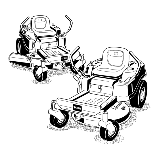
TimeCutter
®
SS 3200 and SS 4200
Riding Mowers
Model No. 74620—Serial No. 311000001 and Up
Model No. 74622—Serial No. 311000001 and Up
G014462
To register your product or download an Operator's Manual or Parts Catalog at no charge, go to www.Toro.com.
Original Instructions (EN)
Advertisement
Table of Contents

Related Manuals for Toro SS 3200


Summary of Contents for Toro SS 3200
-
Page 1: Riding Mowers
SS 3200 and SS 4200 Riding Mowers Model No. 74620—Serial No. 311000001 and Up Model No. 74622—Serial No. 311000001 and Up G014462 To register your product or download an Operator's Manual or Parts Catalog at no charge, go to www.Toro.com. Original Instructions (EN) -
Page 2: Introduction
Authorized Service The engine exhaust from this product contains chemicals known to the State of Dealer or Toro Customer Service and have the model and serial numbers of your product ready. Figure 1 California to cause cancer, birth defects, identifies the location of the model and serial numbers or other reproductive harm. -
Page 3: Table Of Contents
Cleaning and Storage .......... 43 Introduction..............2 Troubleshooting............44 Safety ................4 Schematics ..............46 Safe Operating Practices ........4 Toro Riding Mower Safety ........6 Slope Indicator............. 7 Safety and Instructional Decals ......8 Product Overview ............12 Controls ............. 13 Operation..............14 Think Safety First .......... -
Page 4: Safety
Operator’s Manual pertains. Safety information in addition to the instructions found in • Always wear eye protection when operating the the ANSI standard below can be found in Toro Riding mower. Mower Safety at the end of this section. - Page 5 A hitch kit is available for this machine and can be • Remove or mark obstacles such as rocks, tree limbs, obtained by contacting an Authorized Toro Dealer. etc. from the mowing area. Tall grass can hide Do not tow without first installing this manufacturer obstacles.
-
Page 6: Toro Riding Mower Safety
• Maintain or replace safety and instruction decals as necessary. • Use only genuine Toro replacement parts to ensure that original standards are maintained. Toro Riding Mower Safety The following list contains safety information specific to Toro products or other safety information that you must know that may not be included in the ANSI standards. -
Page 7: Slope Indicator
Slope Indicator G011841 Figure 3 This page may be copied for personal use. 1. The maximum slope you can safely operate the machine on is 15 degrees. Use the slope chart to determine the degree of slope of hills before operating. Do not operate this machine on a slope greater than 15 degrees. Fold along the appropriate line to match the recommended slope. -
Page 8: Safety And Instructional Decals
Safety and Instructional Decals Safety decals and instructions are easily visible to the operator and are located near any area of potential danger. Replace any decal that is damaged or lost. 114-1606 1. Entanglement hazard, belt—keep all guards in place. 106-8717 1. - Page 9 119-8814 1. Parking position 4. Neutral 120-5465 2. Fast 5. Reverse 3. Slow 1. Bypass lever position for 2. Bypass lever position for pushing the machine operating the machine 119-8815 1. Parking position 4. Neutral Battery Symbols 2. Fast 5. Reverse Some or all of these symbols are on your battery 3.
- Page 10 119-8874 1. Low speed 2. High speed 119-3468 1. Choke 5. Power take-off (PTO), Blade control switch on some models 2. Fast 6. Blade control switch—Off 3. Continuous variable setting 7. Blade control switch—On 4. Slow...
- Page 11 120-2239 1. Warning—read the Operator’s Manual. 5. Warning—do not use split ramps, use a full ramps when transporting machine. 2. Warning—read the instructions before servicing or performing 6. Loss of traction/control hazard, slopes—loss of traction/control maintenance; move the motion control levers to the park on a slope, disengage the blade control switch (PTO), (brake) position, remove the ignition key and disconnect the proceed off the slope slowly.
-
Page 12: Product Overview
Product Overview G014525 Figure 4 Models with 32 inch decks 1. Footrest 5. Control panel 9. Deflector 13. Front caster wheel 10. Engine 2. Height of cut lever 6. Operator seat 3. Motion control levers 7. Rear drive wheel 11. Washout fitting 8. -
Page 13: Controls
Controls into the park position when you stop the machine or leave it unattended. Become familiar with all of the controls in Figure 4, Figure 5, and Figure 6 before you start the engine and Smart Speed™ Control System Lever operate the machine. -
Page 14: Operation
Operation Note: Determine the left and right sides of the machine from the normal operating position. Think Safety First Operating Safety Please carefully read all of the safety instructions and decals in the safety section. Knowing this information could help you, your family, pets or bystanders avoid injury. -
Page 15: Before Starting
• The blades are disengaged. DANGER • The motion control levers are in the park position. In certain conditions during fueling, static electricity can be released causing a spark which The safety interlock system also is designed to stop can ignite the gasoline vapors. A fire or explosion the engine when the control levers are out of the park from gasoline can burn you and others and can position and you rise from the seat when the blades... -
Page 16: Starting The Engine
Filling the Fuel Tank Important: Do Not overfill fuel tank. Fill the fuel tank to the bottom of the filler neck. Make sure the engine is shut off and the motion The empty space in the tank allows the fuel to controls are in the park position. -
Page 17: Operating The Blades
G014460 G014459 Figure 14 1. Control panel 4. Off 2. Ignition key—run position 5. Run 3. Ignition key—start position 6. Start 5. After the engine starts, move the throttle lever to Fast (Figure 13). If the engine stalls or hesitates, Figure 13 move the throttle lever back to Choke for a few seconds. -
Page 18: Testing The Safety Interlock System
the park position. Start the engine. While the engine is running, engage the blade control switch, and rise slightly from the seat; the engine should stop. 4. While sitting on the seat, move the blade control switch to Off, and lock the motion control levers in the park position. - Page 19 WARNING Removing you hands from the motion control levers while the machine is in motion can result in a loss of control causing harm to you or bystanders. Always stop the machine and move the motion control levers to the park position before adjusting the Smart Speed™...
-
Page 20: Stopping The Machine
G014476 G008953 Figure 20 Figure 21 1. Height-of-cut lever 3. 4.5 inch (115 mm), To go straight, apply equal pressure to both motion Transport position control levers (Figure 20). 2. Height-of-cut positions To turn, release the pressure on the motion control lever toward the direction you want to turn. -
Page 21: Adjusting The Motion Control Levers
Adjusting the Motion Control To Push the Machine Levers 1. Park the machine on a level surface and disengage the blade control switch. 2. Move the motion control levers outward to park Adjusting the Height position, stop the engine, and wait for all moving The motion control levers can be adjusted higher or parts to stop before leaving the operating position. -
Page 22: Grass Deflector
To Operate the Machine Grass Deflector Move the bypass levers inward and push them back The mower has a hinged grass deflector that disperses in the horizontal slot (Figure 24) to engage the wheel clippings to the side and down toward the turf. motors. -
Page 23: Blade Maintenance
Toro replacement blade. Mowing Direction Alternate mowing direction to keep the grass standing straight. This also helps disperse clippings which enhances decomposition and fertilization. -
Page 24: Maintenance
Maintenance Note: Determine the left and right sides of the machine from the normal operating position. Recommended Maintenance Schedule(s) Maintenance Service Maintenance Procedure Interval • Check the safety interlock system. • Check the air cleaner for dirty, loose or damaged parts. •... -
Page 25: Lubrication
Lubrication 4. Connect a grease gun to each fitting (Figure 25 and Figure 26). Pump grease into the fittings until grease begins to ooze out of the bearings. Greasing the Bearings 5. Wipe up any excess grease. Service Interval: Every 25 hours—Grease all lubrication points. -
Page 26: Engine Maintenance
Engine Maintenance Replace a dirty, bent, or damaged element. Handle new elements carefully; do not use if the rubber seal is damaged. Servicing the Air Cleaner 4. Clean all air cleaner components of any accumulated dirt or foreign material. Prevent any dirt from Service Interval: Before each use or daily—Check the entering the carburetor. - Page 27 2. Park the machine so that the drain side is slightly lower than the opposite side to assure the oil drains completely. 3. Disengage the blade control switch and move the motion controls outward to the park position. 4. Stop the engine, remove the key, and wait for all moving parts to stop before leaving the operating position.
-
Page 28: Servicing The Spark Plug
G014536 G005177 Figure 32 3. Adapter 1. Oil filter 2. Gasket 15. Slowly pour approximately 80% of the specified oil into the filler tube (Figure 29). 16. Install the oil fill cap/dipstick and push firmly into Figure 31 place (Figure 29). 1. -
Page 29: Cleaning The Blower Housing
Cleaning the Blower Housing To ensure proper cooling, make sure the grass screen, cooling fins, and other external surfaces of the engine are kept clean at all times. Annually or every 100 hours of operation (more often under extremely dusty, dirty conditions), remove the blower housing and any other cooling shrouds. -
Page 30: Fuel System Maintenance
Fuel System G014689 Maintenance DANGER In certain conditions, gasoline is extremely flammable and highly explosive. A fire or explosion from gasoline can burn you and others and can damage property. • Perform any fuel related maintenance when the engine is cold. Do this outdoors in an open area. Wipe up any gasoline that spills. -
Page 31: Electrical System Maintenance
Electrical System WARNING Maintenance Incorrect battery cable routing could damage the machine and cables causing sparks. Sparks can cause the battery gasses to explode, WARNING resulting in personal injury. • Always disconnect the negative (black) CALIFORNIA battery cable before disconnecting the Proposition 65 Warning positive (red) cable. -
Page 32: Servicing The Fuses
Figure 37 1. Positive battery post 3. Red (+) charger lead G014540 2. Negative battery post 4. Black (-) charger lead Figure 38 1. Main-30 amp 2. Charge circuit-25 amp Note: Do not run the machine with the battery disconnected, electrical damage may occur. 4. -
Page 33: Drive System Maintenance
Drive System 1. Locate the shaft on the electric brake where the brake link arms are connected. Maintenance 2. Rotate the shaft forward to release the brake. Checking the Tire Pressure Service Interval: Every 25 hours—Check tire pressure. Maintain the air pressure in the front and rear tires as specified. -
Page 34: Mower Maintenance
4. Damage wear or damage. File down any nicks and sharpen the blades as necessary. If a blade is damaged or worn, replace it immediately with a genuine Toro replacement Checking for Bent Blades blade. For convenient sharpening and replacement, you may want to keep extra blades on hand. -
Page 35: Removing The Blades
The blades must be replaced if a solid object is hit, if the blade is out of balance, or the blade is bent. To ensure optimum performance and continued safety conformance of the machine, use genuine Toro replacement blades. Replacement blades made by other manufacturers may result in non-conformance with safety standards. -
Page 36: Leveling The Mower Deck
Leveling the Mower Deck Check to ensure the mower deck is level any time you install the mower or when you see an uneven cut on your lawn. The mower deck must be checked for bent blades prior to leveling; any bent blades must be removed and replaced. - Page 37 8. Loosen the rear locking nut on the hanger bracket just enough to allow the hanger to be adjusted (Figure 51). G009682 Figure 50 Mower Decks with Two Blades 1. Blades side to side 3. Outside cutting edges 2. Sail area of blade 4.
-
Page 38: Adjusting The Front-To-Rear Blade Slope
Adjusting the Front-to-Rear Blade Slope Check the front-to-rear blade level any time you install G009658 the mower. If the front of the mower is more than 5/16 inch (7.9 mm) lower than the rear of the mower, adjust the blade level using the following instructions: 1. -
Page 39: Removing The Mower
3. Set the height-of-cut at the lowest cutting position [1-1/2 inch (38 mm)]. 4. Using a spring removal tool, (Toro part no. 92-5771), remove the idler spring from the deck hook to remove tension on the idler pulley and roll the belt... -
Page 40: Installing The Mower
(Figure 60). G015129 Figure 59 6. Using a spring removal tool, (Toro part no. 92-5771), Mower Decks with 1 Blade install the idler spring over the deck hook and placing tension on the idler pulley and mower belt (Figure 59 1. - Page 41 42 inch Decks WARNING Inspect the grass deflector for damage before each use. An uncovered discharge opening could allow the Replace any damaged parts before use. lawn mower to throw objects in the operator’s or bystander’s direction and result in serious injury. 1.
-
Page 42: Cleaning
Cleaning Note: If the mower is not clean after one washing, soak it and let it stand for 30 minutes. Then repeat the process. Washing the Underside of the 8. Run the mower again for one to three minutes to Mower remove excess water. -
Page 43: Storage
Storage Important: Do not store stabilizer/conditioned gasoline over 30 days. Cleaning and Storage 11. Remove the spark plug(s) and check its condition; refer to Servicing the Spark Plug in the Engine 1. Disengage the blade control switch, move the Maintenance section. With the spark plug(s) motion controls outward to the park position, stop removed from the engine, pour two tablespoons of the engine, and remove the key. -
Page 44: Troubleshooting
Troubleshooting Problem Possible Cause Corrective Action The engine overheats. 1. The engine load is excessive. 1. Reduce ground speed. 2. The oil level in the crankcase is low. 2. Add oil to the crankcase. 3. The cooling fins and air passages 3. - Page 45 Problem Possible Cause Corrective Action There is abnormal vibration. 1. The engine mounting bolts are loose. 1. Tighten the engine mounting bolts. 2. The engine pulley, idler pulley, or blade 2. Tighten the appropriate pulley. pulley is loose. 3. The engine pulley is damaged. 3.
-
Page 46: Schematics
Schematics G014644 Electrical Diagram (Rev. A) - Page 47 Notes:...
- Page 48 Countries Other than the United States or Canada Customers who have purchased Toro products outside the United States or Canada should contact their Toro Distributor (Dealer) to obtain guarantee policies for your country, province, or state. If for any reason you are dissatisfied with your Distributor’s service or have difficulty obtaining guarantee information, contact the Toro importer.
Need help?
Do you have a question about the SS 3200 and is the answer not in the manual?
Questions and answers
what other engine is compatible with the sv470-3219 kohler
Any Kohler Courage single-cylinder engine from model SV470 to SV620 is compatible with the Toro SS 3200 that uses the Kohler SV470-3219. A special long block is available to replace these models regardless of horsepower, and it supports both gravity-fed and fuel pump fuel systems.
This answer is automatically generated
WHERE IS THE GROUND WIRE