Advertisement
Quick Links
Register at www.Toro.com.
Original Instructions (EN)
TimeCutter
Riding Mower
Model No. 74710—Serial No. 400000000 and Up
Model No. 74720—Serial No. 400000000 and Up
Model No. 74725—Serial No. 400000000 and Up
Form No. 3409-409 Rev B
®
SS 3225 and SS 4200
*3409-409* B
Advertisement

Related Manuals for Toro SS 3225


Summary of Contents for Toro SS 3225
- Page 1 Form No. 3409-409 Rev B TimeCutter ® SS 3225 and SS 4200 Riding Mower Model No. 74710—Serial No. 400000000 and Up Model No. 74720—Serial No. 400000000 and Up Model No. 74725—Serial No. 400000000 and Up *3409-409* B Register at www.Toro.com.
- Page 2 Replace all parts including, but not limited to, tires, belts, blades, and fuel system components with original Toro parts. For all models that do not have Toro engines, please refer to the engine manufacturer’s information included with the machine. Labeled power ratings are supplied by the engine manufacturer in accordance with SAE testing and gross/net power rating standards (J1940, J1995, J1349).
- Page 3 Slope Indicator ............5 product properly and safely. Safety and Instructional Decals ......... 6 Product Overview ............10 You may contact Toro directly at www.Toro.com for product Controls ...............10 safety and operation training materials, accessory information, Before Operation ............11 help finding a dealer, or to register your product.
- Page 4 Safety Replacing the In-Line Fuel Filter.......31 Electrical System Maintenance ........32 Electrical System Safety...........32 This machine has been designed in accordance with ANSI Servicing the Battery..........32 standard B71.1-2012. Servicing the Fuses ..........34 Drive System Maintenance .........34 Checking the Tire Pressure ........34 General Safety Releasing the Electric Brake ........35 Mower Maintenance ...........35...
- Page 5 Slope Indicator G011841 g011841 Figure 4 This page may be copied for personal use. 1. The maximum slope you can safely operate the machine on is 15 degrees. Use the slope chart to determine the degree of slope of hills before operating. Do not operate this machine on a slope greater than 15 degrees. Fold along the appropriate line to match the recommended slope.
- Page 6 Safety and Instructional Decals Safety decals and instructions are easily visible to the operator and are located near any area of potential danger. Replace any decal that is damaged or missing. decal93-7009 93-7009 1. Warning—do not operate the mower with the deflector up or removed;...
- Page 7 decal132-0872 132-0872 1. Thrown object 3. Severing hazard of hand hazard—keep bystanders or foot—keep away from away from the machine. moving parts. 2. Thrown object hazard, 4. Entanglement raised baffle—do not hazard—keep away operate the machine with from moving parts; keep an open deck;...
- Page 8 decal131-3947 131-3947 1. Trim—slow 3. Mow—fast 2. Tow—medium decal121-0771 121-0771 1. Choke 4. S 2. F 5. Power take-off (PTO)—Blade-control switch 3. Continuous-variable setting...
- Page 9 decal132-0869 132-0869 1. Warning—read the 3. Cutting hazard of hand, 5. Ramp tipping 7. Tipping hazard on Operator's Manual. hazard—when loading slopes—do not use on mower blade; pinching hazard of hand, belt—keep onto a trailer, do not use slopes near open water; do hands and feet away from dual ramps;...
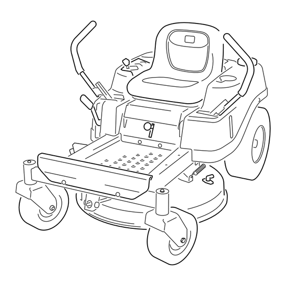
- Page 10 Product Overview g020240 Figure 5 1. Footrest 5. Control panel 9. Deflector 13. Front caster wheels 2. Height-of-cut lever 6. Operator seat 10. Engine 3. Motion-control lever 7. Rear drive wheel 11. Washout fitting 4. Smart-speed lever 8. Fuel-tank cap 12.
- Page 11 Contact your Authorized Service Dealer or • Do not remove the fuel cap or add fuel to the fuel tank Distributor or go to www.Toro.com for a list of all approved while the engine is running or while hot. attachments and accessories.
- Page 12 Using Stabilizer/Conditioner • Keep the fuel-dispenser nozzle in contact with the rim of the fuel tank or container opening at all times until fueling Use a fuel stabilizer/conditioner in the machine to provide is complete. Do not use a nozzle lock-open device. the following benefits: •...
- Page 13 Checking the Engine-Oil Level Before you start the engine and use the machine, check the oil level in the engine crankcase; refer to Checking the Engine-Oil Level (page 13). Breaking in a New Machine New engines take time to develop full power. Mower decks and drive systems have higher friction when new, placing additional load on the engine.
- Page 14 Using the Safety-Interlock Positioning the Seat System WARNING If the safety-interlock switches are disconnected or damaged, the machine could operate unexpectedly, causing personal injury. • Do not tamper with the interlock switches. • Check the operation of the interlock switches daily and replace any damaged switches before operating the machine.
- Page 15 Adjusting the Motion-Control During Operation Levers During Operation Safety Adjusting the Height General Safety You can adjust the motion-control levers higher or lower for • The owner/operator can prevent and is responsible for maximum comfort (Figure 12). accidents that may cause personal injury or property damage.
- Page 16 • Do not change the governor speed or overspeed the engine. • Use accessories and attachments approved by Toro only. Slope Safety • Slow down the machine and use extra care on hillsides. Travel up and down on hillsides. Turf conditions can affect the stability of the machine.
- Page 17 Operating the Ignition Switch Starting and Shutting Off the Engine 1. Turn the ignition key to the S position (Figure 16). TART Note: When the engine starts, release the key. Starting the Engine Important: Do not engage the starter for more than 5 seconds at a time.
- Page 18 Shutting Off the Engine Driving the Machine 1. Disengage the blades by moving the blade-control The drive wheels turn independently, powered by hydraulic switch to the O position (Figure 14). motors on each axle. You can turn 1 side in reverse while you turn the other forward, causing the machine to spin rather 2.
- Page 19 Driving Backward 3. Adjust the lever to the desired position. 1. Move the levers to the center, unlocked position. The following are only recommendations for use. Adjustments vary by grass type, moisture content, and the 2. To go backward, slowly pull the motion-control levers height of the grass.
- Page 20 Stopping the Machine Adjusting the Anti-Scalp Rollers To stop the machine, move the motion-control levers to and outward to the P position, disengage the EUTRAL blade-control switch, ensure that the throttle is in the F For Machines with 107 cm (42-inch) position, and turn the ignition key to O .
- Page 21 If a blade is damaged or worn, replace generally the best one to use. When cutting grass longer than it immediately with a genuine Toro replacement blade. 15 cm (6 inches) tall, you may want to cut the lawn twice to ensure an acceptable quality of cut.
- Page 22 After Operation Note: Do not start the machine. Note: You can now push the machine by hand. After Operation Safety General Safety • Clean grass and debris from the cutting units, mufflers, and engine compartment to help prevent fires. Clean up oil or fuel spills.
- Page 23 Transporting the Machine Use a heavy-duty trailer or truck to transport the machine. Ensure that the trailer or truck has all necessary brakes, lighting, and marking as required by law. Please carefully read all the safety instructions. Knowing this information could help you, your family, pets, or bystanders avoid injury.
- Page 24 Loading the Machine Use extreme caution when loading or unloading machines onto a trailer or a truck. Use a full-width ramp that is wider than the machine for this procedure. Back up the ramp and drive forward down the ramp (Figure 26).
- Page 25 Maintenance Note: Determine the left and right sides of the machine from the normal operating position. Recommended Maintenance Schedule(s) Maintenance Service Maintenance Procedure Interval • Change the engine oil and filter. After the first 5 hours • Check the safety-interlock system. •...
- Page 26 29) with a rag. • To ensure optimum performance and continued safety certification of the machine, use only genuine Toro Note: Make sure to scrape any paint off the front of replacement parts and accessories. Replacement parts the fitting(s). and accessories made by other manufacturers could be dangerous, and such use could void the product warranty.
- Page 27 Engine Maintenance Engine Safety Shut off the engine before checking the oil or adding oil to the crankcase. Servicing the Air Cleaner Service Interval: Before each use or daily—Clean and check the air cleaner foam element. Every 50 hours—Replace the air cleaner paper g015016 Figure 31 element.
- Page 28 Installing the Foam and Paper Elements 3. To keep dirt, grass clippings, etc., out of the engine, clean the area around the oil-fill cap and dipstick before Important: To prevent engine damage, always operate removing it (Figure 33). the engine with the complete foam and paper air cleaner assembly installed.
- Page 29 g027477 g027477 Figure 35 6. Slowly pour approximately 80% of the specified oil into the filler tube and slowly add the additional oil to bring it to the Full mark (Figure 36). g029369 g029369 Figure 34 5. Change the engine-oil filter. Note: Ensure the oil-filter gasket touches the engine, and then turn the filter an extra 3/4 turn.
- Page 30 g027478 g027478 Figure 37 Checking the Spark Plug Important: Do not clean the spark plug(s). Always replace the spark plug(s) when it has: a black coating, worn electrodes, an oily film, or cracks. Note: If you see light brown or gray on the insulator, the engine is operating properly.
- Page 31 Fuel System Maintenance DANGER In certain conditions, fuel is extremely flammable and highly explosive. A fire or explosion from fuel can burn you, others, and can damage property. • Perform any fuel-related maintenance when the engine is cold. Do this outdoors in an open area. Wipe up any fuel that spills.
- Page 32 Electrical System Maintenance Electrical System Safety g027590 g027590 • Disconnect the battery before repairing the machine. Disconnect the negative terminal first and the positive last. Connect the positive terminal first and the negative last. • Charge the battery in an open, well-ventilated area, away from sparks and flames.
- Page 33 3. When the battery is fully charged, unplug the charger WARNING from the electrical outlet, then disconnect the charger Incorrect battery-cable routing could damage leads from the battery posts (Figure 42). the machine and cables causing sparks. Sparks can cause the battery gasses to explode, resulting in personal injury.
- Page 34 Servicing the Fuses Drive System Maintenance The electrical system is protected by fuses. It requires no maintenance; however, if a fuse blows, check the component/circuit for a malfunction or short. Checking the Tire Pressure Fuse type: • Main—F1 (30 A, blade-type) Service Interval: Every 25 hours—Check tire pressure.
- Page 35 Releasing the Electric Brake Mower Maintenance You can manually release the electric brake by rotating the Servicing the Cutting Blades link arms forward. Once the electric brake is energized, the brake resets. To ensure a superior quality of cut, keep the blades sharp. For 1.
- Page 36 3 mm (1/8 inch), the blade spindle could 4. Rotate the same blade 180 degrees so that the opposing be bent. Contact an Authorized Toro Dealer for cutting edge is now in the same position (Figure 49).
- Page 37 The blades must be replaced if a solid object is hit, if the blade is out of balance, or if the blade is bent. For best performance and continued safety conformance of the machine, use genuine Toro replacement blades. Replacement blades made by other manufacturers may result in non-conformance with safety standards.
- Page 38 Leveling from Side to Side Note: If both measurements are not within 5 mm (3/16 inch), an adjustment is required; continue with 1. Park the machine on a level surface and disengage the this procedure. blade-control switch. 6. Move to the left side of the machine. 2.
- Page 39 Note: Check and adjust the side-to-side blade level if you have not checked the setting; refer to Leveling from Side to Side (page 38). 4. Carefully rotate the blades so they are facing front to rear (Figure 58 Figure 59). G014631 G014634 g014634...
- Page 40 8. Slide the mower deck out from underneath the machine. Note: Retain all parts for future installation. Installing the Mower Deck 1. Park the machine on a level surface and disengage the blade-control switch. 2. Move the motion-control levers outward to the P position, shut off the engine, remove the key, and wait for all moving parts to stop before leaving the operating position.
- Page 41 6. Place the spring on the rod, with the end wires down, and between the grass deflector brackets. 7. Slide the rod through second grass deflector bracket (Figure 63 Figure 64). 8. Insert the rod at the front of the grass deflector into the short standoff on the deck.
- Page 42 Model with 107 cm (42-inch) Deck Only 1. Cover 2. Screw 5. Using a spring-removal tool (Toro Part No. 92-5771), remove the idler spring from the deck hook to remove tension on the idler pulley, and roll the belt off of the...
- Page 43 (Figure 66 Figure 67). 7. Using a spring-removal tool (Toro Part No. 92-5771), Washing the Underside of the install the idler spring over the deck hook and place Mower tension on the idler pulley and the mower belt...
- Page 44 Storage 8. Turn the water off and remove the coupling from the washout fitting. Cleaning and Storage Note: If the mower is not clean after 1 washing, soak it and let it stand for 30 minutes. Then, repeat the 1. Park the machine on a level surface and disengage the process.
- Page 45 13. Remove the spark plug(s) and check its condition; refer to Removing the Spark Plug (page 30). With the spark plug(s) removed from the engine, pour 30 ml (2 tablespoons) of engine oil into the spark plug hole. Use the starter to crank the engine and distribute the oil inside the cylinder.
- Page 46 Troubleshooting Problem Possible Cause Corrective Action The engine overheats. 1. The engine load is excessive. 1. Reduce the ground speed. 2. The oil level in the crankcase is low. 2. Add oil to the crankcase. 3. The cooling fins and air passages 3.
- Page 47 Problem Possible Cause Corrective Action The cutting height is uneven. 1. The blade(s) is not sharp. 1. Sharpen the blade(s). 2. A cutting blade(s) is/are bent. 2. Install a new cutting blade(s). 3. The mower is not level. 3. Level the mower from side-to-side and front-to-rear.
- Page 48 Schematics g036806 Electrical Schematic (Rev. A)
- Page 49 Notes:...
- Page 50 Notes:...
- Page 51 Notes:...
- Page 52 Countries Other than the United States or Canada This warranty is not valid in Mexico. Customers who have purchased Toro products outside the United States or Canada should contact their Toro Distributor (Dealer) to obtain guarantee policies for your country, province, or state. If for any reason you are dissatisfied with your Distributor's service or have difficulty obtaining guarantee information, contact the Toro importer.
Need help?
Do you have a question about the SS 3225 and is the answer not in the manual?
Questions and answers