Table of Contents
Advertisement
WARNING
To reduce the risk of fire, burn hazard or other injury,
read the manual carefully and completely before
using your grill.
WARNING
FOR OUTDOOR USE ONLY.
Version No.19000398A0
Note to Consumer/Nota para el usuario/Note destinée à l'utilisateur
Leave this Owner's Manual in a convenient place for future reference.
Deje este Manual del Usuario en un lugar conveniente para referencia en el futuro.
Rangez ce manuel de l'utilisateur dans un endroit pratique pour une consultation future.
SERIAL # ____________________ MFG. DATE ________ PURCHASE DATE: _________
Questions, problems, missing parts? Before returning to your retailer, call our customer service
department at 1-800-913-8999, 8 a.m. - 5 p.m., EST, Monday – Friday.
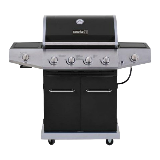
LP GAS GRILL
(pages 1-24)
PARRILLA A GAS LP
GRIL AU GAZ DE PÉTROLE
LIQUÉFIÉ
(page 50-73)
MODEL / MODELO / MODÈLE # 720-0783C
WARNING
This grill is not intended to be installed in or on
recreational vehicles and/or boats.
ITEM / ARTÍCULO / RÉF # 114672
(página 25-49)
®
Advertisement
Table of Contents

Related Manuals for Nexgrill 720-0783C


Summary of Contents for Nexgrill 720-0783C
- Page 1 (página 25-49) GRIL AU GAZ DE PÉTROLE LIQUÉFIÉ (page 50-73) MODEL / MODELO / MODÈLE # 720-0783C WARNING WARNING To reduce the risk of fire, burn hazard or other injury, This grill is not intended to be installed in or on read the manual carefully and completely before recreational vehicles and/or boats.
-
Page 2: Table Of Contents
Table of Contents Precautions WARNING Failure to comply with these instructions could Warranty----------------------------------------------- result in a fire or explosion that could cause Precautions------------------------------------------- serious bodily injury, death, or property damage. Package Contents List------------------------------ Hardware Contents---------------------------------- Parts Diagram --------------------------------------- Parts List----------------------------------------------- WARNING Preparation-------------------------------------------- Your grill will get very hot. -
Page 3: Precautions
Precautions A tank of approximately 12 inches in diameter by 18-1/2 Have your LP gas tank filled by a reputable inches high is the maximum size LP gas tank to use. propane gas dealer and visually inspected and re- qualified at each filling. You must use an OPD gas tank which offers an Do not store a spare LP gas tank under or near Overfill Prevention Device. - Page 4 WARNING Burner Flame Check A strong gas smell, or the hissing sound of gas indicates a serious problem with your gas grill or the LP gas tank. Failure to immediately follow the steps listed below could result in a fire or explosion that could cause serious bodily injury, death, or property damage.
-
Page 5: Package Contents List
Package Contents List A. Firebox --- 1pc. B. Bottom Panel --- 1pc. C. Caster --- 2pcs. D. Swivel Caster with Brake --- 1pc. E. Swivel Caster --- 1pc. F. Tank Tray Bolt --- 1pc. G. Side Panel, Left --- 1pc. H. - Page 6 T. Regular Burner Cooking --- 1pcs. U. Control Knob --- 2pcs. V. AA Size Alkaline ---1pc. W. Grease Tray --- 1pc. X. Grease Cup --- 1pc. Y. Manual Lighting Stick --- 1pc. Z. Cart Frame --- 1pc. A1. Searing Side Burner Cooking B1.
-
Page 7: Hardware Contents
Hardware Contents Item Description Specification Quantity Truss Head Screw 1/4'' x 15mm 41pcs / " Truss Head Screw 5/32'' x 10mm 24pcs Flat Head Screw 5/32'' x 10mm 12pcs Flat Washer 1/4'' 6pcs Flat Washer 5/32'' 4pcs... -
Page 8: Parts Diagram
Parts Diagram... -
Page 9: Parts List
Parts List KEY# DESCRIPTION QUANTITY KEY# DESCRIPTION QUANTITY Main Lid Side Shelf Control Panel, Right Main Lid Screw Side Burner Assembly Burner Pin Assembly Side Burner Igniter Wire Temperature Gauge Searing Burner Lid Temperature Gauge Housing Searing Burner Lid Hinge Rod, Left Logo Searing Burner Hood Buffer A... -
Page 10: Preparation
Preparation Before beginning assembly, make sure all parts are present. Compare parts with package contents list and diagram above. If any part is missing or damaged, do not attempt to assemble the product. Contact customer service at 1-800-913-8999 for replacement parts. •Tools required for assembly: Phillips Screwdriver Truss Screwdriver (not included). - Page 11 Fig.3 (c) Attach left & right side panels (G & H) to bottom panel (B) using (4) Truss head screws (AA) with (4) Lock washers. See Fig.3. Fig.4 (d) Attach back panel (I) to bottom panel (B) using (7) Truss head screws (AA) with (7) Lock washers. Attach Triangle Bracket Left (F1) and Triangle Bracket right (E1) to both side panels (G &...
- Page 12 Attached door handle (K) to door handle seat (D1), Fig.6 See Fig.6. (g) Attach door handle (K) to left door (L) using (2) Truss head screws (BB). Repeat to assemble the other door handle to right door (M). See Fig.7. (h) Attach two doors (L &...
- Page 13 Fig.9 Fig.10 Fig.11 Side Burner Assembly Loosen (2) preinstalled head screws from right side of Firebox (A) as shown. Do not screw out fully; leave ¼ extended for shelf assembly. Through side burner shelf keyholes, hang side burner shelf (N) on two loosened screws. See Fig.
- Page 14 Fig.12 4. Side Burner Valve Assembly (a) Remove two screws from side burner control valve face. Insert the side burner valve into the Side Burner Shelf Control Panel (N). Align the screws on the valve with the large side of the holes on the bezel.
- Page 15 Searing Side Burner Assembly Fig.16 Loosen (2) preinstalled head screws from left side of Firebox (A) as shown. Do not screw out fully; leave ¼ extended for shelf assembly. Through side burner shelf keyholes, hang side burner shelf (O) on two loosened screws. See Fig.16.
- Page 16 Fig.20 (e) Push control knob (U) onto valve control stem. See Fig.20. (f) Plug ignition wire into igniter wire hanging from electrode on underside of burner. See Fig.21. 7. Igniter and Battery Assembly (a) Remove igniter cover and lock washer from igniter.
- Page 17 Fig.23a 8. Side Burner Grates Assembly Replace both grates to each side burner. See Fig.23a. 9. Grease Cup Assembly From the back, pull out grease trays (W & J), remove any packaging materials from it, then insert grease cup (X) into grease tray (W) as shown in Fig.23b. Push grease trays back into grill.
- Page 18 Congratulations page 19 for gas leak check instructions). If a leak is Your Nexgrill® gas grill is now ready for use. found, turn tank valve off and do not use your grill Before the first use and at the beginning of each until the leak is repaired.
-
Page 19: Lighting Instructions
3. Be sure all gas connections are securely Checking for LP gas leaks tightened. 4. Turn on gas supply. Never test for leaks with a flame. Prior to first use, at 5. Open the grill main lid. the beginning of each season, or every time your LP 6. -
Page 20: Lighting Instructions
If Grill Still Fails To Light WARNING 1. Check gas supply and connections for leaks. Never lean over the grill cooking area while Check that all wire connections are secure. lighting your gas grill. Keep your face and body a safe distance (at least 18 inches) from the 2. -
Page 21: Cleaning And Maintenance
Cleaning Exterior Stainless Steel Surfaces Cleaning and Maintenance Weathering and extreme heat can cause exterior stainless steel surfaces to turn tan in color. Machine oils used in To ensure a proper working unit the following proper manufacturing process of stainless steel can also cause care and maintenance is suggested. -
Page 22: Troubleshooting
2. Clean any clogged ports with a stiff wire, such as WARNING an open paper clip. The location of the burner tube with respect to the 3. Inspect each burner for damage (cracks or holes) orifice is vital for safe operation. Check to ensure the and if such damage is found, order and install a new orifice is inside the burner tube before using the gas burner. -
Page 23: Cooking Instructions
Cooking Instructions WARNING WARNING Do not line the bottom of the grill housing with Do not leave the grill unattended. aluminum foil, sand or any substance that will Your grill will get very hot. Never lean over restrict the flow of grease into the grease tray. the cooking area while using your grill. -
Page 24: Grill Cooking Chart
Grill Cooking Chart Warning: To ensure that it is safe to eat, food must be cooked to the minimum internal temperatures listed in the table below. Food Temperature Beef, veal and lamb (pieces and whole cuts) - medium-rare 63°C (145°F) Beef, veal and lamb (pieces and whole cuts) - medium 71°C (160°F) Beef, veal and lamb (pieces and whole cuts) - well done...
Need help?
Do you have a question about the 720-0783C and is the answer not in the manual?
Questions and answers