
Related Manuals for Parker USB-DLA


Summary of Contents for Parker USB-DLA
- Page 1 USB-DLA USB Data Link Adapter User Manual HY33-5010-IB/US Ed. 06/2010 UM-USBDLA-779A06-1.0-201006-02...
- Page 2 The user must analyze all aspects of the application, follow applicable industry standards, and follow the information concerning the product in the current product catalog and in any other materials provided from Parker or its subsidiaries or authorized distributors.
-
Page 3: Table Of Contents
5.1.1. Load the USB drivers 5.2. Plug in the vehicle interface cable 5.3. USB-DLA LED Indicators 5.3.1. LED Colors and Blink codes 6. Software Tools for the USB-DLA 6.1. USB Update Tool 6.2. VAPI Server 6.2.1. Multiple client connections 6.3. - Page 4 Contents 9. Glossary of Terms 10. Index USB Data Link Adapter...
-
Page 5: Introduction
Ignoring this could result in damage to the product. Contact the manufacturer if there is anything you are not sure about or if you have any questions regarding the product and its handling or maintenance. The term "manufacturer" refers to Parker Hannifin Corporation. USB Data Link Adapter... -
Page 6: Precautions
Precautions Precautions 2.1. General safety regulations Work on the hydraulics control electronics may only be carried out by trained personnel who are well-acquainted with the control system, the machine and its safety regulations. ARNING Mounting, modification, repair and maintenance must be carried out in accordance with the manufacturer's regulations. -
Page 7: Construction Regulations
Precautions 2.1.1. Construction regulations AUTION The vehicle must be equipped with an emergency stop which disconnects the supply voltage to the control system's electrical units. The emergency stop must be easily accessible to the operator. The machine must be built if possible, so that the supply voltage to the control system's electrical units is disconnected when the operator leaves the operator’s station. -
Page 8: Usb-Dla Description
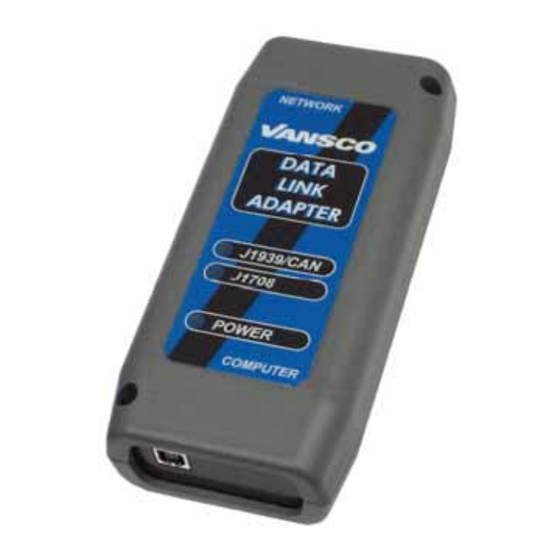
This manual explains the contents of the kit, and how to set up and use the DLA for USB communication. 3.1. Contents of USB-DLA kit The USB-DLA kit is supplied in a high density polyethylene, blow-molded case. The kit includes the following: Table 1: Contents of USB-DLA kit Part No. - Page 9 USB-DLA Description Figure 1: USB-DLA kit USB Data Link Adapter...
-
Page 10: Software Installation
4.1. Installing the USB drivers You must be logged on as an administrator to install the USB-DLA drivers. The latest drivers for the USB-DLA are available from Parker Electronic Controls Division website: http://www.parker.com/ecd. Go to the Customer Toolbox and select Vansco DLA and PGM Drivers. - Page 11 "setup.exe" the following installation screen will appear, click Next to continue: Figure 2: Software setup screen The next screen is a license agreement between the end user and Parker Vansco. Once you have read and agreed to the license click on I Agree.
- Page 12 Click Install to continue. Figure 4: File location After installing the files, a final screen will indicate that the setup program is complete. Click Close to finish the software installation of the USB-DLA. Figure 5: Installation complete USB Data Link Adapter...
-
Page 13: Using The Usb-Dla
Using the USB-DLA Using the USB-DLA 5.1. Plug in the USB cable Connect the DLA to your computer using the USB cable provided. Plug the A-type receptacle into the back of your computer (1), and the B-type receptacle into the DLA (2). -
Page 14: Load The Usb Drivers
Hardware Wizard in order to load the USB drivers. Windows will do this every time the device appears on a new USB port (e.g., if you attach the USB-DLA to a new hub, Windows will want to install the driver for each port on the hub). The USB drivers are loaded like any other USB device. - Page 15 Using the USB-DLA Windows will then load the drivers for the USB-DLA. Figure 8: DLA drivers being loaded A final screen will indicate when the USB-DLA installation is complete. Click Finish to close the window. Figure 9: DLA drivers are now loaded...
-
Page 16: Plug In The Vehicle Interface Cable
DLA is isolated from any earth or vehicle ground. 5.3. USB-DLA LED Indicators The USB-DLA has 3 LEDs for status indication. The LED indicators on the USB-DLA fall into two categories: power status (1 LED) and network status (2 LEDs). 5.3.1. -
Page 17: Software Tools For The Usb-Dla
USB Update Tool OTICE USB update tool is a program for updating the embedded firmware in the USB-DLA. If this is done incorrectly or the wrong firmware is loaded, the DLA can be rendered inoperative. The unit must then be returned to Parker Vansco for reprogramming. - Page 18 Software Tools for the USB-DLA 1. The filename should start with the DLA product number 779. Never program the DLA with firmware file that does not start with 779. 2. The filename should end with the application version number. Never program the DLA with an application code that has a lower version number.
-
Page 19: Vapi Server
VAPI Server A new icon appears in your system tray when you start an RP1210 application that uses the USB-DLA. This is the VAPIserver (Vansco Application Program Interface Server) program; it provides the interface between the applications (such as SimGauges, SimEngine and CANsniff) and the DLA hardware. - Page 20 Software Tools for the USB-DLA J1708/J1587 Tx Count Number of J1708 messages transmitted by DLA J1708/J1587 Rx Count Number of J1708 messages received by DLA Adapter Packets Tx Count Number of packets transmitted by DLA to the PC Adapter Packets Rx Count...
-
Page 21: Multiple Client Connections
RP1210 specification. Some applications will recognize this and present the user with a choice of available APIs. Parker Vansco applications will use the first API on the list. In order to make sure the DLA uses the correct API the installer includes a small PC application called RP1210 Chooser. - Page 22 Running RP1210Chooser.exe provides the screen shown below. Figure 15: RP1210 Chooser dialog Simply select the API required for your device, VE121032 for the USB-DLA, and move it to the top of the list with the arrows on the right hand side of the screen. If...
-
Page 23: Appendix A
7.2. USB-DLA Environmental Specifications The USB-DLA is made to operate in a typical automotive service environment. The unit is protected to extremes of temperature and chemicals. As a handheld unit, the unit can withstand being dropped but is not protected from vehicle stresses such as steam cleaning or pressure washing. - Page 24 Appendix A Table 5: Environmental rating tests passed by USB-DLA Test Spec. Test Description Deviation Ref. EP455 Operating Temperature Level Section 5.1.1 EP455 Storage Temperature Level 2 Section 5.1.2 EP455 Thermal Shock Section 5.1.3 EP455 Operating Voltage Level 1 7 VDC to 32 VDC Section 5.10.1...
- Page 25 Appendix A EP455 Mechanical Shock Handling Bench Level 2 Section 5.14.2.2 EP455 Random Vibration Section 5.15.1 ISO 14982 EMC Susceptibility Level 2 ISO 14982 EMC - Emissions USB Data Link Adapter...
-
Page 26: Appendix B
RP1210 standard, then their engine diagnostic software should work a DLA from any manufacturer. Parker Vansco's industry standard RP1210 API is ve121032.dll. Parker has made every effort to make the USB-DLA RP1210 compliant. It should be usable with test tools from Dearborn, Cummins, and other manufacturers. We... -
Page 27: Software Model
RP1210 to address issues unique to their systems. The TMC RP1210 Specification is available from ATA for a fee. Parker Vansco developed the RP1210 drivers used with the USB-DLA. The latest updates are available on our website: www.parker.com/ecd. 8.3. -
Page 28: Software Files And Locations
Appendix B 8.4. Software Files and Locations If you experience difficulty installing the software or if you want to update only one file it may be easier to manually copy the files into the proper locations. 8.4.1. Files copied during software installation: ve121032.dll: RP1210 API. - Page 29 Appendix B NFORMATION Windows will not use the new USB driver until you have updated the driver in Device Manager. Manually update the driver in Windows, (ie: Settings > Control Panel > System > Hardware > Device Manager). Right click on Vansco USB DLA and select Update Driver. USB Data Link Adapter...
-
Page 30: Glossary Of Terms
Glossary of Terms Glossary of Terms application software A level of software that makes a product (hardware) perform desired functions for the end user. Controller Area Network CAN High One of the wires used in the shielded twisted-pair cable, which provides the positive signal that, when connected with CAN Low, provides a complete CAN differential signal. - Page 31 Glossary of Terms embedded applications. RS232 is an older technology that is slowly being phased out of production in favor of USB. USB Data Link Adapter...
- Page 32 RS232 • 30 Software Files and Locations • 28 Software Installation • 10 Software Model • 27 Software Tools for the USB-DLA • 17 USB Update Tool • 17 USB-DLA Description • 8 USB-DLA Electrical Specifications • 23 USB-DLA Environmental Specifications • 23 USB-DLA LED Indicators •...
Need help?
Do you have a question about the USB-DLA and is the answer not in the manual?
Questions and answers