
Related Manuals for EMAK OM106J


Summary of Contents for EMAK OM106J
- Page 1 OM106J - OM124J EF106J - EF124J (STARJET) SATR 15,5 H SATR 17,5 H SATR 18 H User‘s manual Gebruikershandleiding Bedienungsanleitung Manual de usuario Manuel d’utilisation Instrukcja obsługi Manuale di istruzioni...
- Page 2 1.3.1 1.3.2a...
- Page 3 1.3.2b 1.3.2c 3.3.1a...
- Page 4 3.3.1b 3.3.1c 3.3.1d 3.3.1e...
- Page 5 3.3.2a 3.3.2b 3.3.2c...
- Page 6 3.3.2d 3.3.2e 3.3.2f 3.3.2g 3.3.2h...
- Page 7 3.3.2i 3.3.2j 3.3.2k 3.3.2l 3.3.2m...
- Page 8 3.3.2n 3.3.2o 3.3.2p 3.3.2q 3.4.1...
- Page 9 4.1a 4.1b...
- Page 10 4.2.1a 4.2.1b 5.6a...
- Page 11 5.6b 6.2.2 6.3.3a 6.3.3b 6.3.6a 6.3.6b...
- Page 12 6.3.7a 6.3.7b 6.3.7c 6.3.7d 6.3.7e...
- Page 13 6.3.8a 6.3.9a 6.3.9b 6.3.9c 6.3.10a...
- Page 14 6.3.10b 6.3.10c 6.3.10d 6.3.10e 6.3.10f...
- Page 15 6.3.11 6.3.12a 6.3.12b...
- Page 16 6.3.14...
- Page 17 FOREWORD Dear customer, Thank you for buying a lawn mower from the Seco Group a.s. Seco is recognized in markets throughout Europe and around the world as a manufacturer of high-quality lawn care machines and accessories. This manual contains instructions for safe setup, operation and maintenance of your mower. Read this manual carefully.
-
Page 18: Technical Information
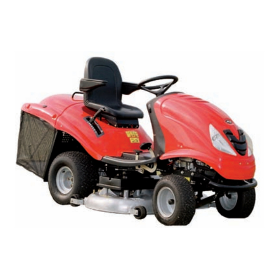
1. TECHNICAL INFORMATION 1.1 Use Model AJ102 or AG122 machines bearing the STARJET brand are double-axled self-propelled lawn mowers that are intended for cutting flat, maintained lawns with a maximum growth height of 10 cm, e.g., in parks, gardens and playgrounds, or on gentle slopes that do not contain foreign objects (fallen branches, stones, solid objects, etc.). - Page 19 1.3 MANUFACTURING PLATE AND OTHER LABELS USED ON THE MACHINE 1.3.1 MANUFACTURING PLATE Each self-propelled mower is marked with the manufacturer’s label, located below the seat. You can access it by lifting the seat. 1. Mower model 2. Engine model 3.
-
Page 20: Technical Parameters
1.4 TECHNICAL PARAMETERS MOWER MODEL BASIC SPECIFICATIONS UNIT AJ102 AG122 Dimensions 2400 x 1060 x 2450 x 1270 x [mm] (length x width x height) 1100 1200 Weight [kg] Speed forward / reverse [km/h] 8 / 4 Cutting height [mm] 30 - 90 30 - 80 Cutting stroke... - Page 21 AJ102 Mower Declared noise Weighted RMS acceleration (min.s Guaranteed emission level RPM ± 100 acoustic Engine at the operator Steering output level (min-1) Seat Floor LpAd (dB) wheel (dB) per EN ISO 11201 BS15 2700 85.0 0.16 2.48 1.72 BS16 2800 83.1...
-
Page 22: Occupational Safety
2. OCCUPATIONAL SAFETY STARJET brand AJ102 and AG122 self-propelled mowers are manufactured according to applicable European safety norms. The manufacturer confirms this in the Declaration of Compliance included at the end of this manual ( 10). If this machine is used properly and according to the manual, it is very safe. If the user does not adhere to work safety and does not heed the warnings in this manual, this self-propelled lawn mower can sever a hand or a foot, or even hurl objects, leading to serious personal injury or death, damage or destruction of the... - Page 23 2.1.3 While using the machine ! The machine must not be used on slopes of more than 10° (17%). ! Transporting other people, animals or objects on the machine is prohibited. Objects may be transported only on a trailer approved by the machine’s manufacturer. ! Even when leaving the machine for a short time, always remove the ignition key.
-
Page 24: Child Safety
! Regularly check the components and, when necessary, replace them according to the manufacturer’s recommendation. 2.2 SAFETY INSTRUCTIONS FOR WORKING ON SLOPES Slopes are a main cause of accidents, loss of control and overturning. These can lead to severe injury or death. -
Page 25: Preparing For Operation
3. PREPARING FOR OPERATION 3.1 UNPACKING AND CONTENT INSPECTION The self-propelled mower is delivered in a fabric cover (1). Some parts of the machine have been dismantled for transport at the factory, and they must be installed before operation. The machine is unpacked and prepared for operation by the dealer as part of pre-sale service. -
Page 26: Grass Catcher
3.3.1 STEERING WHEEL, SEAT AND BATTERY a) Install the steering wheel: Place the wheel on the column (1) and turn it so that the holes in the steering wheel and column meet. 3.3.1a Insert the included peg into the hole (2) and pound it with a hammer. b) Fasten the seat: Place the seat in its position on the machine and fasten it using the screws preinstalled 3.3.1b... -
Page 27: Package Contents
PACKAGE CONTENTS 300-litre grass catcher 360-litre grass catcher 3.3.2a 3.3.2b (1) - Lid, frame and bag (1) - Lid, frame and bag (2) - Lifting lever (2) - Lifting lever (3) - Corner braces (left and right) (3) - Corner braces (left and right) (4) - Handle (4) - Handle (5) - Lower brace... - Page 28 Into the upper holes in the brace that fastens the front tube above, insert M5x16 bolts, secure them with washers and nuts, and lightly tighten them. Also tighten the lower, pre-inserted bolts. 3.3.2h For the catcher on the 360-litre model, a spring (brace) must be bolted into the lower hole on the right-hand side of the front tube, for hitching up the basket.
- Page 29 3.4 INSPECTING BEFORE STARTUP 3.4.1 CHECKING THE ENGINE OIL Before checking the oil, the tractor must be in a horizontal position. The oil cap can be accessed by lifting the seat. Unscrew the dipstick, wipe it clean, reinsert it and screw it back in. Then unscrew it again and read the oil level.
-
Page 30: Control Layout
4. CONTROLLNG THE MACHINE 4.1 CONTROL LAYOUT Accelerator lever Indicator for the brake pedal and parking brake Mowing function control switch when grass catcher is full 4.1a Switch for mowing mechanism Main switch Brake pedal Parking brake control Mulching lid lever Forward drive pedal 4.1b (10) - Page 31 Position Grass catcher full Mowing mechanism and gear (4) MOWING MECHANISM SWITCH Pulling the switch upward turns the mowing mechanism on. Pressing downward shuts the mowing mechanism off. Turning on the mowing mechanism / mowing mechanism is off Turning on the mowing mechanism (5) MAIN SWITCH Turns the engine on and off.
- Page 32 (8) MULCHING LID LEVER This lever has two functions: 1) Mulching – grass clippings are spread underneath the lawn mower 2) Grass collection – grass clippings are collected in the grass catcher When shifting the lever from the collection position to the mulching position (downward), stop the machine and allow the mowing mechanism to run for about 20 seconds to clear remaining grass from the removal tube.
-
Page 33: Mowing Mechanism Height Adjustment Lever
(11) MOWING MECHANISM HEIGHT ADJUSTMENT LEVER This lever sets the height of the mowing mechanism from the ground. The lever has 7 working positions for cutting heights from 3 to 9 cm. The higher the lever’s position number, the taller the grass will be after cutting. -
Page 34: Cruise Control
(4) CRUISE CONTROL The cruise control is used only on long, straight drives. Cruise control must be turned off before any change in direction. Cruise control is on only when the ignition is on. The cruise control can be turned off by stepping on the pedal or shutting off the switch. -
Page 35: Starting The Engine
5.2 STARTING THE ENGINE a) Step on the brake pedal. b) Set the mowing mechanism height lever to position “7”. c) On motorized machines, open the fuel cap (only on machines with 15.5-hp BS15 engines). d) Set the accelerator lever as follows: - On machines with 2-cylinder engines, to the “MAX”... -
Page 36: Setting The Height Of The Mowing Mechanism
Use the mowing mechanism height lever to set the mechanism’s working position and thereby the cutting height. Set the mowing mechanism switch to “ON”. Conditions for turning on the mowing mechanism: - the driver is sitting on the driver seat - the grass catcher or deflector is installed - the AUT/MAN switch (optional equipment) is in the “AUT”... -
Page 37: Driving The Machine
5.5 DRIVING THE MACHINE General warning before driving: Make sure the parking brake is disengaged. The parking brake lever must not remain in position “2” 4.2). The parking brake automatically releases when the service brake pedal is pressed. The bypass lever must be set to position “1”, i.e., the bypass must be turned off. When driving toward the mowing area, the mowing mechanism must be turned off and set to the highest position, i.e., the mowing mechanism’s height adjustment lever must be in position “7”. -
Page 38: Driving On A Slope
5.5.4 DRIVING ON A SLOPE Right Mower models AJ102 and AG122 can work on slopes up to 10° (17%). When working on a slope, the following principles must be observed: Be extra careful when riding on a slope. Always drive at a slower speed. Wrong Drive only perpendicularly to the contour line, i.e., up and down. - Page 39 6.1 OVERVIEW OF INSPECTION AND MAINTENACNE INTERVAL Regular maintenance Maintenance by hours of use Seasonal maintenance After Activity After the After the Before mowing Before After each first 2 first 5 Monthly mowing season each use hours hours season (storing the machine) Check the oil (transmission,...
-
Page 40: Daily Inspection And Maintenance
6.2 DAILY INSPECTION AND MAINTENANCE - Before beginning any maintenance or service, familiarize yourself again with all instructions, restrictions and recommendations in this manual. - Before cleaning, maintenance or repair, always remove the key from the ignition. - When working, always wear appropriate work clothes and shoes. When handling the cutting blades or during activities that pose a cutting risk, wear appropriate work gloves. - Page 41 WASHING THE MACHINE Before washing, park the machine on an appropriate level surface. Grass catcher: - remove the grass catcher from the machine, wash it and let it dry. Plastic parts: - clean with a sponge and soapy water. Mowing mechanism: - wash from inside, including internal parts and removal tube.
- Page 42 Further details on checking and adding oil, including information on the type and amount of oil, are given in a separate manual provided by the engine manufacturer. - If you come into contact with used oil, we recommend thoroughly washing your hands with soap and water.
-
Page 43: Replacing Fuses
When replacing a light bulb that has a bayonet simply turn (loosen) the burnt-out bulb and remove it from the socket. Then insert a new bulb into the socket and turn it until it locks. 6.3.3a When changing a halogen bulb first release the three metal brackets, remove the burnt- out bulb, insert a new one, and reengage the brackets. -
Page 44: Replacing Blades
Carefully tighten the blades’ mounting bolts using a torque wrench set to ±3 Nm. This torque is reached at exactly the moment when the tangential spring under a blade’s mounting bolt is completely compressed. After that, do not tighten the screw further. ... - Page 45 As soon as the front edge is at the correct height, place an appropriate washer of the corresponding height underneath it. Check the height of the mowing mechanism’s rear edge. It must be 10-13 mm higher than the front edge, i.e., 23-25 mm above the ground. If the height is incorrect, adjust it 6.3.7b by loosening the screw (3) on the mowing mechanism frame.
-
Page 46: Steering Maintenance
Remove the spring (3) from the shoulder of the tension pulley and loosen the spring upward (4). 6.3.10b Stand on the right side of the machine. Push the tensioner pulley toward the large pulley. This loosens the V-belt. Then remove the belt. 6.3.10c Remove the cotter pins (5) from the front pins (6) and from both rear pins (7) of the mowing mechanism suspension. -
Page 47: Replacing Wheels
6.3.14 REPLACING WHEELS Before changing one of the wheels, park the tractor on a solid, level surface, shut off the engine and remove the key from the ignition. Change the wheel as follows: Raise the machine using an appropriate jack on the side on which the wheel is to be changed. -
Page 48: Troubleshooting
6.4 LUBRICATION Lubricate the machine according to the following schedule. The bearings of the tensioning pulleys, guide pulleys and mowing mechanism are self-lubricating. Before storing the machine for an extended time, thoroughly lubricate all areas shown in the schedule. Symbol Explanation Grease SAE 30 oil... - Page 49 Check the tension of the belts ( 6.3.8 and 6.3.9). If necessary, adjust the tension. The mowing Check for damaged bearings. Repair or replace, if necessary. mechanism pulls the Check the mowing height and adjust it, if necessary. Turf is often pulled on uneven terrain. turf Check to see if the blades are warped.
-
Page 50: Ordering Replacement Parts
Check the drive belt tension ( 6.3.12). If necessary, adjust the tension. Check the belt guide. If necessary, adjust it. The drive belt jumps Check for damaged pulleys. Replace them, if necessary. out during operation Check the space between the drive coupling mechanism. If there are deviations, the coupling pulley support may be bent. -
Page 51: Disposing Of The Machine
- Never store the lawn mower with a full tank of fuel inside a building or in a poorly ventilated area, where there are fuel fumes, open flame, sparks or ignition sources, a furnace, central heating, dry rags, etc. Handle fuels and lubricants carefully. They are highly flammable and careless handling can cause severe burns or property damage. -
Page 52: Ec Declaration Of Conformity
10. EC DECLARATION OF CONFORMITY in accordance with: Regulation No. 2006/42/EC (government notice NV 176/2008 Coll.) Regulation No. 2004/108/EC (government notice NV 616/2006 Coll.) Regulation No. 2000/14/EC (government notice NV 9/2002 Coll.) A. We: The Seco Group a.s., Šaldova 408/30, Prague 8 plant: 02 Jičín, Jungmannova 11 Org ID: 60193450 hereby issue the following declaration:... - Page 53 in accordance with: Council Directive No. 2006/42/EC (government decree NV 176/2008 Coll.) Council Directive No. 2004/108/EC (government decree NV 616/2006 Coll.) Council Directive No. 2000/14/EC (government decree NV 9/2002 Coll.) A. We: The Seco Group a.s., Šaldova 408/30, Prague 8 závod 02 Jičín, Jungmannova 11 Org ID: 60193450 hereby issue the following declaration:...
-
Page 54: Czech Republic
UPOZORNĚNÍ! - Tato uživatelská příručka musí doprovázet přístroj během celé své životnosti. Producer: Seco GROUP a.s. Pobřežní 44/362 Praha 8 division 02 AGS, Jičín Jungmannova 11 50648 Jičín CZECH REPUBLIC Distributor: EMAK s.p.a. - Via Fermi, 4 42011 Bagnolo in Piano (Reggio Emilia) Italy Member of the YAMA group Dic/2008...
Need help?
Do you have a question about the OM106J and is the answer not in the manual?
Questions and answers