Table of Contents
Advertisement
Quick Links
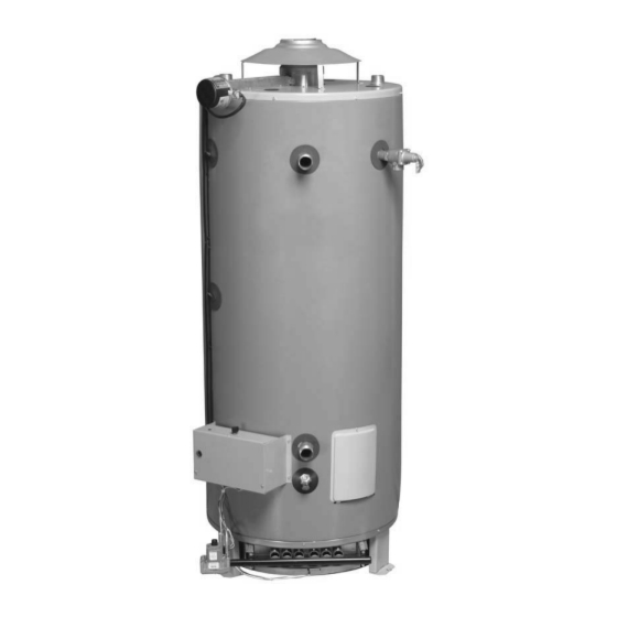
Commercial Gas
Water Heater
Installation
Instructions and
Use & Care Guide
for Signature Series models with prefix JWS and AJWS
WARNING:
If the information in these instructions is
not followed exactly, a fire or explosion
may result causing property damage, per-
sonal injury or death.
Do not store or use gasoline or other flam-
mable vapours and liquids in the vicinity of
this or any other appliance.
WHAT TO DO IF YOU SMELL GAS
• Do not try to light any appliance.
• Do not touch any electrical switch; do
not use any phone in your building.
• Immediately call your gas supplier from
a neighbor's phone. Follow the gas sup-
plier's instructions.
• If you cannot reach your gas supplier,
call the fire department.
Installation and service must be performed
by a qualified installer, service agency or
the gas supplier.
GSW Water Heating is a division of GSW Water Products Inc.
GSW WATER HEATING
599 Hill Street West
Fergus, ON, Canada N1M 2X1
To obtain technical, warranty or service assistance during
or after the installation of this water heater, call toll free:
1-888-479-8324
When calling for assistance, please have the following
information ready:
1. Model number
2. 5 digit product number
3. Serial number
4. Date of installation
5. Place of purchase
Table of Contents . . . . . . . . . . . . . . . . . . . . . . . . . . . . 2
70305 REV.C (06-01)
Advertisement
Table of Contents

Related Manuals for GSW JWS


Summary of Contents for GSW JWS
-
Page 1: Water Heater Safety
Table of Contents ......2 70305 REV.C (06-01) GSW Water Heating is a division of GSW Water Products Inc. -
Page 2: Table Of Contents
Your safety and the safety of others is very important. We have provided many important safety messages in this manual and on your appliance. Always read and obey all safety messages. This is the safety alert symbol. This symbol alerts you to potential hazards that can kill or hurt you and others. All safety messages will follow the safety alert symbol and either the word “DANGER”... -
Page 3: Installation Instructions
INSTALLATION INSTRUCTIONS the front of the water heater. When referring to this water Consumer Information heater always have the information listed on the data plate readily available. This water heater is design-certified by CSA International as a Category I, non-direct vented water heater which takes its Retain your original receipt as proof of purchase. -
Page 4: Clearances And Accessibility
require insulation of the water piping and drain piping to Important: Air for combustion and ventilation must not protect against freezing. The drain and controls must be come from a corrosive atmosphere. Any failure due to cor- easily accessible for operation and service. Maintain rosive elements in the atmosphere is excluded from war- proper clearances as specified on the data plate. -
Page 5: Combustion Air Supply And Ventilation
Important: If installing over carpeting, the carpeting must Figure 1 may be used as a reference guide to locate the be protected by a metal or wood panel beneath the water specific clearance locations. A minimum of 610mm (24 in) of heater. -
Page 6: Air Requirements
• Exhaust gas vents must be installed with U.L.listed type ating simultaneously. B vent pipe according to the vent manufacturer’s instruc- The area in which the heater is located is classified as either tions and the terms of its listing. “an unconfined space”... - Page 7 Air Opening Requirements (a) EQUIPMENT LOCATED IN CONFINED SPACES; ALL AIR FROM INSIDE THE BUILDING. Two permanent openings (top and bottom) shall be provided connecting the confined space (e.g., closet/small room) with the unconfined space. Each opening shall have a free area of one square inch per 1,000 BTU/hour (22 cm²/kW) input of all appliances in the confined space, but not less than 100 square inches (645 cm²).
-
Page 8: Water System Piping
Drafthood/Damper Installation WARNING Do not operate heater with damper in closed position, it must be in the open position dur- ing water heater operation. Do not negate the action of any existing safety or opera- tional controls. Install the supplied drafthood and damper on the flue outlet collar. - Page 9 faucet and check all connections for leaks. Water Heater Inlet Tube Inlet Tube Dip Tube Model Base # (Optional Front) (Optional Back) Space Heating 75-125 60238 60239 60239 If this unit is to be used to supply both space heating and 80-199 60053 60057...
- Page 10 Outlet Hot Water Boosted to Fixtures Temperature Thermometer Shut-off valve Shut-off valve Temperature and Thermometer Pressure Relief Valve Temperature and Pressure Relief Valve Check Valve Typical Pre-Heater Booster Heater Thermal Expansion Shut-off valve Tank 45mm (1 1/2 in) 1 1/2” Cold Shut-off valve water supply Cold water supply...
- Page 11 Thermal Outlet Expansion Boosted Pressure Tank 45mm (1 1/2 Temperature Reducing Thermometer Hot Water Thermometer in) Cold water 1 1/2” Cold Valve to Fixtures Pre-Heated water supply supply Water to the Booster Shut-off valve Check valve Shut-off valve Temperature and Pressure Relief Valve Temperature and Pressure Relief Valve...
-
Page 12: Gas Supply And Piping
Temperature and Pressure Relief Valve The Temperature & Pressure Relief Valve: • Must not be in contact with any electrical part. WARNING • Must be connected to an adequate discharge line. • Must not be rated higher than the working pressure shown on the data plate of the water heater. -
Page 13: Gas Pressure
“National Fuel Gas Code” or “Natural Gas and Propane • If the gas lines are to be tested at a pressure less than 14 inches water column, the water heater must be iso- Installation Code” for the recommended gas pipe size of lated from the gas supply piping system by closing its other materials. - Page 14 Natural Gas Pipe Capacity (Cu. ft./hr) Capacity of gas pipe of different diameters and lengths in cu. ft. per hr. with pressure drop of 0.3 in. and specific gravity of 0.60 (natural gas). Nominal Iron Pipe Length of Pipe, Feet Size, in.
-
Page 15: Electrical Connections
ELECTRICAL CONNECTIONS Note: The power supply to this water heater must be prop- erly polarized, [120 volts from the hot lead (black) to ground and 0 volts from the neutral lead (white) to ground] other- WARNING wise, the unit will not operate. Electrical Shock Hazard 6. -
Page 16: Wiring Diagram
WIRING DIAGRAM... -
Page 17: Installation Checklist
INSTALLATION CHECKLIST Electrical Connections Water Heater Location Requirements • Unit must be “hard-wired” to a dedicated 120V power supply. • Centrally located with the water piping system. Located • Proper polarity. as close to the gas piping and vent pipe system as pos- •... -
Page 18: Operating Instructions
OPERATING INSTRUCTIONS 8. Set thermostat to desired setting. 1. STOP! Read the safety information above on this label. 9. Turn on all electric power to the appliance. 2. Turn off all electric power to the appliance. 3. Set the thermostat to the lowest setting. 4. -
Page 19: Emergency Shut Down
Emergency Shut Down Operational Conditions Condensation Important: If overheating occurs or the gas supply fails to shut off, close the manual gas supply valve and turn the gas Moisture from the products of combustion condenses on the control knob to the off position. Turn off the electrical supply tank surface and the outside jacket of the water heater and to the unit and close the cold water supply valve. -
Page 20: Maintenance Of Your Water Heater
MAINTENANCE OF YOUR WATER Temperature and Pressure Relief Valve HEATER WARNING Draining and Flushing It is recommended that the tank be drained and flushed every 6 months to remove sediment which may buildup dur- ing operation. Note: Warranty is null and void in the event lime & scale Explosion Hazard deposits are allowed to exceed two inches in depth. -
Page 21: Anode Rod Inspection
as it will void any warranties, stated or implied. A special anode is available for this complaint. This rod may reduce but not eliminate water odour problems. The water supply system may require special filtration equipment from a water conditioning company to successfully eliminate all water odour problems. -
Page 22: Trouble Shooting Chart
TROUBLESHOOTING FLOWCHART... - Page 23 THERMOSTAT TROUBLESHOOTING FLOWCHART No voltage or low voltage from purple wire between thermostat board & ECO board. Replace With an ohmmeter set at X1, check sensor(s). orange wires on set pot. (3,000 ohms at lowest OHMs setting & 0 ohms reading no good at highest setting.) Replace...
-
Page 24: Repair Parts Illustration
REPAIR PARTS ILLUSTRATION When ordering repair parts always give the following information: 1. Model, serial, and product number 2. Type of gas 3. Item number 4. Parts description Repair Parts List Part Name and Description Part Name and Description Drafthood Control Box Cover Diptube (Top) Transformer... -
Page 25: Warranty
GSW will not assume any expense or liability for unauthorized returns, nor repairs made by a person who has not been authorized by GSW or one of its authorized dealers. GSW Units/parts must be replaced with GSW or John Wood products to be eligible for Warranty.
Need help?
Do you have a question about the JWS and is the answer not in the manual?
Questions and answers