
Related Manuals for Raymarine Dragonfly


Summary of Contents for Raymarine Dragonfly
- Page 1 Dr a g o n fly Dr a g o n fly Release 9 Installation and operation instructions Date: 03-2014 Document number: 81345-3-EN © 2014 Raymarine UK Limited...
- Page 3 Product handbooks The latest versions of all English and translated handbooks are available to download in PDF format from the website www.raymarine.com. Please check the website to ensure you have the latest handbooks.
-
Page 5: Table Of Contents
Contents Chapter 1 Important information......7 6.6 DownVision check..........40 6.7 Shortcuts page............. 40 TFT Displays ............... 7 6.8 Applications ............41 Water ingress .............. 7 6.9 View switcher............42 Disclaimers ..............7 Chart cards and memory cards........8 Chapter 7 Managing display data ...... 43 EMC installation guidelines .......... - Page 6 14.4 Sonar / DownVision troubleshooting ....95 14.5 Miscellaneous troubleshooting ......96 Chapter 15 Technical support ......97 15.1 Raymarine customer support ......98 Chapter 16 Technical specification....99 16.1 Technical specification ........100 Chapter 17 Spares and accessories ....103 17.1 Accessories .............
-
Page 7: Chapter 1 Important Information
End-User Licence Agreement included in the documentation for this product or supplied with the memory card (as applicable). Raymarine does not warrant that this product is error-free or that it is compatible with products manufactured by any person or entity other than Raymarine. -
Page 8: Chart Cards And Memory Cards
Declaration of conformity • micro Secure Digital High-Capacity (microSDHC) Note: The maximum card capacity supported is 32 GB. Raymarine UK Ltd. declares that this product is compliant with the essential requirements of EMC directive 2004/108/EC. Speed class rating The original Declaration of Conformity certificate may be viewed For best performance it is recommended that you use Class 10 on the relevant product page at www.raymarine.com. -
Page 9: Product Disposal
Directive requires the recycling of waste electrical and electronic equipment. Whilst the WEEE Directive does not apply to some Raymarine products, we support its policy and ask you to be aware of how to dispose of this product. IMO and SOLAS... - Page 10 Dragonfly / Dragonfly 7...
-
Page 11: Chapter 2 Document And Product Information
Chapter 2: Document and product information Chapter contents • 2.1 Document information on page 12 • 2.2 Product overview on page 13 Document and product information... -
Page 12: Document Information
PDF format. These PDF files can be viewed on a PC / on software releases. laptop, tablet, smartphone, or on the latest generation of Check the Raymarine website to ensure you have the latest Release 9 Raymarine multifunction displays. software and user manuals. www.raymarine.com. -
Page 13: Product Overview
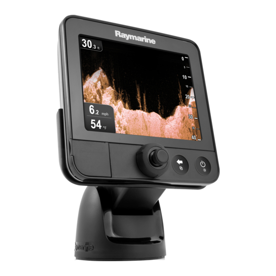
2.2 Product overview The unit connects directly to a Raymarine DownVision transducer and a vessels power supply. D13000-1 CHIRP Sonar overview The Dragonfly display is a standalone Fishfinder and chart CHIRP sonar produces a conical shaped beam, the coverage of plotter combo multifunction display. - Page 14 Dragonfly / Dragonfly 7...
-
Page 15: Chapter 3 Planning The Installation
Chapter 3: Planning the installation Chapter contents • 3.1 Installation checklist on page 16 • 3.2 Parts supplied on page 17 • 3.3 Compatible transducers on page 17 • 3.4 Tools required for installation on page 18 • 3.5 Software updates on page 18 •... -
Page 16: Installation Checklist
Plan your system. Obtain all required equipment and tools. Site all equipment. Route all cables. Drill cable and mounting holes. Make all connections into equipment. Secure all equipment in place. Power on and test the system. Dragonfly / Dragonfly 7... -
Page 17: Parts Supplied
3.2 Parts supplied 3.3 Compatible transducers The parts supplied with your product are shown below. This product is compatible with the following Raymarine DownVision transducers. Supplied with: E70085, E70226, E70230 and E70231 Part Mounting Construc- Item Description number Description Type... -
Page 18: Tools Required For Installation
• If in doubt as to the correct procedure for updating your product software, refer to your dealer or Raymarine technical support. Caution: Downloading software updates The software update process is carried out at your own risk. -
Page 19: Warnings And Cautions
3.6 Warnings and cautions 3.7 Selecting a location for the transducer Important: Before proceeding, ensure that you have read and understood the warnings and cautions provided in the This product is supplied with a transom mount transducer. The Chapter 1 Important information section of this document. -
Page 20: Cable Routing
Transducer dimensions The transducer’s dimensions including the mounting bracket are shown below. D12638-1 202.6 mm (8 in) 117.4 mm (4.6 in) Dragonfly / Dragonfly 7... -
Page 21: Selecting A Location For The Display
3.9 Selecting a location for the display General location requirements When selecting a location for the unit it is important to consider a number of factors. ( 7 . 8 5 0 0 7 i n . 7 i ( 1 9 Ventilation requirements ( 9 . -
Page 22: Installation Process
84 mm (3.3 in) D13037-1 7 inch display cradle orientation The 7 inch display can be mounted in ‘cradle up’ or ‘cradle down’ orientation. Cradle Up Cradle Down The cradle mounting steps are the same regardless of orientation. Dragonfly / Dragonfly 7... -
Page 23: Chapter 4 Mounting
Chapter 4: Mounting Chapter contents • 4.1 Mounting the transducer on page 24 • 4.2 Cradle mounting on page 25 • 4.3 Fitting the display in the cradle on page 26 • 4.4 Fitting the 7 inch display in the cradle — Cradle down on page 26 •... -
Page 24: Mounting The Transducer
10. Loosen the transducer pivot bolt approximately 3 turns to enable adjustment. D12643-1 Pivot bolt location 11. Adjust the angle of the transducer using the ratchet mechanism, one click at a time until the transducer face is parallel with the waterline. D12651-1 Dragonfly / Dragonfly 7... -
Page 25: Cradle Mounting
4.2 Cradle mounting The transducer position will be adjusted further during testing (see Testing the transducer). Follow the steps below to mount the display’s cradle. Before mounting ensure that you have: • selected a suitable location. • installed the transducer and routed the power/transducer cable to the selected display location. -
Page 26: Fitting The Display In The Cradle
2. Insert the blanking plug into the hole that will be left exposed. 3. Ensure the Safety Latch is in the unlocked position. 4. Fit the display to the cradle following the relevant procedure. 5. Push the Safety Latch in and turn clockwise to the locked position. Dragonfly / Dragonfly 7... -
Page 27: Security
• Raymarine does not guarantee the security of your display when using a lock. • Raymarine will not be held liable for any damage caused to the display or cradle due to the use of a lock. Locking hole location If a lock is to be fitted to the display to secure it to the cradle then the blanking plug must be removed. -
Page 28: Removing The Display From The Bracket
2. Disconnect the cable from the back of the display. 3. Push the cradle release clip away from the display as shown. When the display releases you will hear a click. 4. Remove the display from the cradle. Dragonfly / Dragonfly 7... -
Page 29: Surface Mounting
4.7 Surface mounting Note: The supplied gasket provides a seal between the unit and a suitably flat and stiff mounting surface or binnacle. The display can be surface mounted using the optional surface The gasket should be used in all installations. It may also mounting kit. -
Page 30: Testing The Transducer
8. Re-tighten the pivot bolt before re-testing. 9. When you achieve optimum performance at the desired vessel speeds you can finish the transducer mounting. Note: It may be necessary to make several adjustments to the transducer before obtaining optimum performance. Dragonfly / Dragonfly 7... -
Page 31: Chapter 5 Cables And Connections
Chapter 5: Cables and connections Chapter contents • 5.1 General cabling guidance on page 32 • 5.2 Cable connection on page 32 Cables and connections... -
Page 32: General Cabling Guidance
• Unless otherwise stated use only standard cables of the correct type, supplied by Raymarine. • Ensure that any non-Raymarine cables are of the correct quality and gauge. For example, longer power cable runs may require larger wire gauges to minimize voltage drop along the run. -
Page 33: Breakers/Fusesc/Ircuit Protection
The information below is provided as guidance to help protect your product. The example illustrations provided are for common vessel power arrangements, if you are unsure how to provide the correct level of protection then please consult a Raymarine authorized dealer for support. Fuse and breaker rating... - Page 34 Dragonfly / Dragonfly 7...
-
Page 35: Chapter 6 Getting Started
Chapter 6: Getting started Chapter contents • 6.1 Display power on page 36 • 6.2 Controls on page 36 • 6.3 Initial set up procedures on page 37 • 6.4 GPS Check on page 38 • 6.5 Sonar check on page 39 •... -
Page 36: Display Power
• Press once to power the unit on. • When turned on, pressing the power button will display the Shortcuts page. • Press and hold to turn the display off. UniControl The UniControl consists of Rotary, Joystick and push button controls. Dragonfly / Dragonfly 7... -
Page 37: Initial Set Up Procedures
The simulator mode is switched on / off in the System Settings selection. menu. Note: Raymarine recommends that you do NOT use the simulator mode whilst navigating. Note: The simulator will NOT display any real data. This includes safety messages. -
Page 38: Gps Check
The accuracy of the GPS receiver depends on the parameters detailed above, especially the azimuth and elevation angles which are used in triangulation to calculate your position. Dragonfly / Dragonfly 7... -
Page 39: Sonar Check
6.5 Sonar check Checking GPS operation You can check that the GPS is functioning correctly using the Checking the sonar application Chart application. 1. Select a view from the View switcher which includes the Chart application. From the sonar application: 1. -
Page 40: Downvision Check
The Sonar / DownVision ping can be disabled and enabled from the shortcuts page. 1. If the Sonar and DownVision are active then select Disable Sonar. 2. If the Sonar and DownVision are inactive then select Enable Sonar. Dragonfly / Dragonfly 7... -
Page 41: Applications
6.8 Applications Note: • When enabled, the Sonar will ping only if the view displayed Applications available on the display are shown below. contains the Sonar application or if the Chart application is Chart application — provides a 2D graphical view of your displayed fullscreen. -
Page 42: View Switcher
3. Use the Joystick or Rotary control to highlight the pane you want to be active. 4. Press the OK button to confirm. The selected view is displayed and a border is placed around the active pane. Dragonfly / Dragonfly 7... -
Page 43: Chapter 7 Managing Display Data
Chapter 7: Managing display data Chapter contents • 7.1 Memory cards overview on page 44 • 7.2 Saving user data and user settings on page 44 • 7.3 Resetting your system on page 46 Managing display data... -
Page 44: Memory Cards Overview
The Chart menu is displayed. 3. Select Waypoints or Tracks. The Waypoints or Track list is displayed. 4. Select Import/Export. 5. Select Retrieve from Card. The file browser is displayed. 6. Navigate to the gpx file you want to import. Dragonfly / Dragonfly 7... - Page 45 7. Select the file. 3. Select Back-up Settings. A confirmation dialog is displayed. When complete a saving complete dialog box is displayed. 8. If there is a naming conflict between waypoints or tracks 4. Select OK to acknowledge and return to normal operation, or already on your system and the waypoints or tracks you are 5.
-
Page 46: Resetting Your System
The sonar setting can be reset to factory defaults. From the Tools & Settings page: 1. Select System Settings. 2. Select Sonar Set-up. 3. Select Sonar Reset. A confirmation dialog is displayed. 4. Select Yes to reset the sonar settings. Dragonfly / Dragonfly 7... -
Page 47: Chapter 8 Chart Application
Chapter 8: Chart application Chapter contents • 8.1 Chart application overview on page 48 • 8.2 Chart application controls on page 51 • 8.3 Chart context menu on page 51 • 8.4 Navigation on page 52 • 8.5 Chart selection on page 52 •... -
Page 48: Chart Application Overview
Orientation — States the orientation mode that the chart is new chart types and regions from around the globe. using (North-up, or Course-up). Refer to the Raymarine website: for the latest information on available LightHouse charts. Range — Chart scale indicator (shown in selected system units). - Page 49 End User License Agreement (EULA) before downloading and using LightHouse charts. 1. Go to the LightHouse charts page of the Raymarine website: http://www.raymarine.com/lighthousecharts/. 4. Click ‘View the terms of use’. 5. Read and ensure you FULLY understand the End User License Agreement (EULA).
- Page 50 2. Right click on the file and select the Extract Here option from • Hotmaps the zip options. Note: Refer to the Raymarine website (www.raymarine.com) for the latest list of supported chart cards. 3. Once all files have been extracted select the chart files.
-
Page 51: Chart Application Controls
8.2 Chart application controls 8.3 Chart context menu The Chart application consists of 2 modes: Motion mode Placing the cursor over an area in the chart application and and Cursor mode. Options and settings are available via the pressing the OK button displays a context menu showing the application and context menus. -
Page 52: Navigation
1. Select Ok on the waypoint arrival alarm pop up message. Note: You can set the approach distance (radius) at which the waypoint arrival alarm will sound using the Alarms menu from the Tools & Settings page: Tools & Settings > Alarms > Waypoint Arrival. Dragonfly / Dragonfly 7... -
Page 53: Chart Orientation
8.6 Chart orientation 8.7 Chart Detail The orientation of a chart refers to the relationship between the The chart detail setting determines the amount of detail shown chart and the direction that you are travelling in. in the Chart application. The mode you choose applies to all chart views, and is restored Selecting the Low option for the Chart Detail disables the at power up. -
Page 54: Boat Position
Changing the boat position You can change the position the vessel icon is displayed on-screen. From the Chart application menu: 1. Select Chart Settings. 2. Select Boat Position. Selecting Boat Position switches the boat position between Center and Offset. Dragonfly / Dragonfly 7... -
Page 55: Cog Vector
8.10 COG Vector 8.11 Deep Water The chart application can be set to display a green line to Water depth can be represented using blue shading with white represent Course Over Ground (COG). used to represent deep water. The depth at which water color turns from blue shading to white can be changed to suit user requirements. -
Page 56: Chart Objects
The Chart Object Dialog is displayed. 3. Selecting available options will display detailed information about that item. 4. Selecting the position in the dialog will close the information dialog and position the cursor over the object. Dragonfly / Dragonfly 7... -
Page 57: Chapter 9 Waypoints And Tracks
Chapter 9: Waypoints and Tracks Chapter contents • 9.1 Waypoints overview on page 58 • 9.2 Tracks on page 64 • 9.3 Import and Export on page 65 • 9.4 Waypoints and tracks storage capacity on page 65 Waypoints and Tracks... -
Page 58: Waypoints Overview
A waypoint is placed at the cursor’s location. Example 2 — DownVision application Placing a waypoint at your vessel's position From the Chart application: 1. If required press the Back button to enter motion mode. Dragonfly / Dragonfly 7... - Page 59 2. Press the OK button again to open the menu. 4. Waypoint group — This is the currently selected waypoint group. 3. Select Place Waypoint. A confirmation pop up message is displayed. 5. Rename Group — Rename the current group. 4.
- Page 60 2. Select the waypoint you want to erase. alternative.) The waypoint information page is displayed. • Position (Latitude and Longitude of the waypoint.) 3. Select Erase. • Bearing and Range (Bearing and range from vessel.) The erase waypoint pop up message is displayed. Dragonfly / Dragonfly 7...
- Page 61 4. Select Yes to confirm, or No to cancel. You can also select a waypoint from the list to view its details, or if accessed from the Chart application set a goto or display the Erasing all waypoints from the system waypoint in the Chart application.
- Page 62 Red Triangle Seaweed Oyster Blue Cross Green Cross Green Can Green Nun Blue Circle Green Circle Red Can Red Nun Blue Square Green Square Yellow Can Yellow Nun Blue Triangle Green Triangle Fish Trap Brushpile Anchor Wreck Dragonfly / Dragonfly 7...
- Page 63 Preferred Marks Post Skull Diamond T Ledge Fish Diamond Quarter Filled Triangle Fish 1 Star Fish 2 Star Fish 3 Star School Fish Lobster Small Fish Rocks Reef Private Reef Public Reef Dolphin Shark Billfish Tank Reef Ball Sailboat Sportsfisher Trawler Swimmer Martini...
-
Page 64: Tracks
1. Use the Joystick to highlight the Track. A confirmation dialog is displayed. The cursor changes to the Track cursor. 4. Select Yes to confirm. 2. Press the OK button. The Track context menu is displayed. Dragonfly / Dragonfly 7... -
Page 65: Import And Export
9.3 Import and Export 9.4 Waypoints and tracks storage capacity Waypoints and Tracks can be imported and exported using a memory card. The display can store the following quantities of waypoints and For details on importing and exporting waypoints and tracks tracks. - Page 66 Dragonfly / Dragonfly 7...
-
Page 67: Chapter 10 Sonar Application
Chapter 10: Sonar application Chapter contents • 10.1 Sonar application overview on page 68 • 10.2 Sonar and DownVision application controls on page 69 • 10.3 Range on page 70 • 10.4 Display options on page 70 • 10.5 Sensitivity adjustments on page 72 Sonar application... -
Page 68: Sonar Application Overview
This is known as ‘background noise’ or The following images show how different bottom conditions are ‘clutter’ and is controlled by the Sensitivity settings. If required represented on-screen: you can adjust the setting manually. Dragonfly / Dragonfly 7... -
Page 69: Sonar And Downvision Application Controls
10.2 Sonar and DownVision application • Adjust Sonar — (opens the Adjust Sonar menu.) controls Accessing the context menu You can access the context menu by following the steps below. The Sonar and DownVision applications each consist of 2 modes: Scrolling mode and Cursor mode. Options and settings 1. -
Page 70: Range
Options menu. 4. If Manual is chosen select Manual Zoom The manual zoom factor dialog is displayed. 5. Adjust the setting to the required value. 6. Select Back or use the Ok button to confirm the setting. Dragonfly / Dragonfly 7... - Page 71 Adjusting the position of the zoomed area 1. Select Display Options. 2. Select White Line. In Zoom mode the system automatically selects the zoom position so that the bottom is always in the lower half of the Selecting White Line will switch the bottom line On and Off. display.
-
Page 72: Sensitivity Adjustments
The new values remain set even when you switch off the display, they are applied to both the active view and any other views containing the same application. Adjusting the Contrast From the application menu: 1. Select Adjust Sonar or Adjust DownVision. Dragonfly / Dragonfly 7... -
Page 73: Chapter 11 Downvision Application
Chapter 11: DownVision application Chapter contents • 11.1 DownVision application overview on page 74 • 11.2 Sonar and DownVision application controls on page 74 • 11.3 Range on page 75 • 11.4 Display options on page 76 • 11.5 Sensitivity adjustments on page 77 DownVision application... -
Page 74: Downvision Application Overview
The context menu provides the data for the position of the cursor: • Depth • Range The context menu also provides the following menu items: • Place Waypoint • Adjust DVision — (opens the Adjust DownVision menu.) Dragonfly / Dragonfly 7... -
Page 75: Range
11.3 Range Accessing the context menu You can access the context menu by following the steps below. The Range and Range Shift functions enable you to change 1. Use the Joystick to highlight an object or area. the range of depth displayed on-screen. Changes to the Range 2. -
Page 76: Display Options
If required you can reposition the portion of the image that is zoomed so that an alternative area is displayed. In Zoom mode, from the application menu: 1. Select Display Options. Dragonfly / Dragonfly 7... -
Page 77: Sensitivity Adjustments
11.5 Sensitivity adjustments 2. Select Contrast. 3. Use the Rotary control to adjust the Contrast to the required Settings can be adjusted using the application menu to enhance value, or the image that is displayed on-screen. 4. Press the OK button to switch to Auto mode. Sensitivity options are: A tick is displayed in the Auto box to signify auto is enabled. - Page 78 Dragonfly / Dragonfly 7...
-
Page 79: Chapter 12 Tools & Settings
Chapter 12: Tools & Settings Chapter contents • 12.1 Alarms on page 80 • 12.2 System Settings menu on page 82 • 12.3 Backup and reset on page 86 Tools & Settings... -
Page 80: Alarms
Alarms menu. Accessing the alarms menu The steps below describe how to access the alarms menu. 1. Select Tools and Settings from the View switcher. 2. Select Alarms. The Alarms menu is displayed. Dragonfly / Dragonfly 7... - Page 81 Alarms menu The table below show the alarms available and related settings. Deep Water If this option is set to On, an alarm is triggered when the Deep: depth exceeds the value that you specify. This option is only • Off (default) available when the sonar is enabled.
-
Page 82: System Settings Menu
Icelandic Italian Japanese Korean Norwegian Polish Portuguese (Brazilian) Russian Spanish Swedish Turkish Selecting a language From the Tools & Settings menu: 1. Select System Settings. 2. Select Language: 3. Select the relevant language from the list. Dragonfly / Dragonfly 7... - Page 83 Units set-up You can specify your preference for the units of measurement that will be used in all applications. Menu item Description Options Distance Units The units of measure that will be used in all applications for • Nautical Miles the display of all values related to distance.
- Page 84 Allows you to specify the local time zone that will be used, in • –13 to +13 hours (in 0.5 hour increments) Local Time: UTC terms of an offset from UTC (Universal Coordinated Time), in 0.5 hour increments. Dragonfly / Dragonfly 7...
- Page 85 Maintenance menu This menu provides access to systems settings reset and diagnostics. Menu item Description Options About This Unit Displays a list of details about your unit. • Device • Serial No. • Software Settings Reset This option resets your menu options to factory default. It will •...
-
Page 86: Backup And Reset
Backup, Reset and restore user settings, Reset settings and data. Restart GPS Restart the internal GPS receiver. Sonar Reset Reset the internal sonar module. For details on performing a sonar reset please refer to 7.3 Resetting your system Dragonfly / Dragonfly 7... -
Page 87: Chapter 13 Maintenance
Chapter 13: Maintenance Chapter contents • 13.1 Service and maintenance on page 88 • 13.2 Cleaning on page 88 • 13.3 Transducer cleaning on page 89 Maintenance... -
Page 88: Service And Maintenance
13.2 Cleaning This product contains no user serviceable components. Please Best cleaning practices. refer all maintenance and repair to authorized Raymarine When cleaning this product: dealers. Unauthorized repair may affect your warranty. • Do NOT wipe the display screen with a dry cloth, as this could Routine equipment checks scratch the screen coating. -
Page 89: Transducer Cleaning
13.3 Transducer cleaning Growth can collect on the bottom of the transducer, this can reduce performance. To prevent the build up of sea growth, coat the transducer with a thin layer of water based antifouling paint, available from your local marine dealer. Reapply paint every 6 months or at the beginning of each boating season. - Page 90 Dragonfly / Dragonfly 7...
-
Page 91: Chapter 14 Troubleshooting
Chapter 14: Troubleshooting Chapter contents • 14.1 Troubleshooting on page 92 • 14.2 Power up troubleshooting on page 93 • 14.3 GPS troubleshooting on page 94 • 14.4 Sonar / DownVision troubleshooting on page 95 • 14.5 Miscellaneous troubleshooting on page 96 Troubleshooting... -
Page 92: Troubleshooting
The troubleshooting information provides possible causes and corrective action required for common problems associated with marine electronics installations. All Raymarine products are, prior to packing and shipping, subjected to comprehensive test and quality assurance programs. However, if you experience problems with the operation of your product this section will help you to diagnose and correct problems in order to restore normal operation. -
Page 93: Power Up Troubleshooting
14.2 Power up troubleshooting Problems at power up and their possible causes and solutions are described here. Problem Possible causes Possible solutions The system (or part of it) does not start Power supply problem. Check relevant fuses and breakers. Check that the power supply cable is sound and that all connections are tight and free from corrosion. -
Page 94: Gps Troubleshooting
Note: A GPS Status screen is available within the unit. This provides satellite signal strength and other relevant information. Dragonfly / Dragonfly 7... -
Page 95: Sonar / Downvision Troubleshooting
14.4 Sonar / DownVision troubleshooting Problems with the Sonar or DownVision and their possible causes and solutions are described here. Problem Possible causes Possible solutions Sonar / DownVision data not available. Unit power supply fault. Check the unit power supply and cables. Sonar disabled. -
Page 96: Miscellaneous Troubleshooting
Check that the power source is of the correct voltage and sufficient current. Ensure you have the latest software. Check the Raymarine website regularly for software updates for your product www.raymarine.com. Corrupt data / other unknown issue. Perform a Settings and Data Reset. -
Page 97: Chapter 15 Technical Support
Chapter 15: Technical support Chapter contents • 15.1 Raymarine customer support on page 98 Technical support... -
Page 98: Raymarine Customer Support
15.1 Raymarine customer support Raymarine provides a comprehensive customer support service. You can contact customer support through the Raymarine website, telephone and e-mail. If you are unable to resolve a problem, please use any of these facilities to obtain additional help. -
Page 99: Chapter 16 Technical Specification
Chapter 16: Technical specification Chapter contents • 16.1 Technical specification on page 100 Technical specification... -
Page 100: Technical Specification
12 V dc GPS specification voltage Channels Operating voltage 10.8 V dc to 15.6 V dc 10.8 V dc to 15.6 V dc range Approximately 35 seconds in optimum Cold start conditions Receiver IC Sensitivity –159 dBm Tracking Dragonfly / Dragonfly 7... - Page 101 1575.43MHz Operating frequency Signal Acquisition Automatic Almanac Update Automatic Geodetic Datum WGS-84, alternatives available through Raymarine displays. 1 second Update Rate Antenna Ceramic chip Accuracy • Without SBAS: <= 15 metres 95% of the time • With SBAS: <= 5 metres 95% of the time...
- Page 102 Dragonfly / Dragonfly 7...
-
Page 103: Chapter 17 Spares And Accessories
Chapter 17: Spares and accessories Chapter contents • 17.1 Accessories on page 104 Spares and accessories... -
Page 104: Accessories
5.7” part number 7” part number A80206 Carrying case Trolling Motor Mount A80207 A80207 4 m (13.1 ft) extension cable A80224 A80224 Surface mount adaptor A80223 A80287 Sun cover R70134 A80285 Mounting bracket / cradle R70135 R70302 Dragonfly / Dragonfly 7... - Page 106 www.ra ym a rin e .c o m...
Need help?
Do you have a question about the Dragonfly and is the answer not in the manual?
Questions and answers