
Related Manuals for Rivacold RSI


Summary of Contents for Rivacold RSI
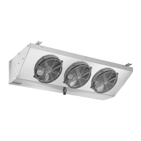
- Page 1 MANUALE USO E MANUTENZIONE AEROEVAPORATORI A SOFFITTO USE AND MAINTENANCE HANDBOOK CEILING UNIT COOLERS RSI REV. 05 04/08...
- Page 2 RSI Pag. 2 REV. 05 04/08...
- Page 3 • Non usare la macchina priva di protezioni (carenatura e griglia) • Evitare che la macchina sia esposta a fonti di calore. • In caso di incendio usare un estintore a polvere. • Il materiale dell’imballaggio deve essere smaltito nei termini di legge. RSI Pag. 3 REV. 05 04/08...
- Page 4 • sbrinamento: • matricola n° resistenze (*) Secondo la normativa EN 378/1 appartengono al Gruppo 2 i seguenti gas : R22,R134a,R507,R404A,R407C,R410A,R410B Tutti gli evaporatori RSI rientrano nella categoria 0 secondo la direttiva 97/23/CE (P.E.D.) Fig. 1 P+250 Etichetta di riconoscimento...
- Page 5 Per la movimentazione della macchina, usare guanti di protezione antitaglio o sistema di sollevamento idoneo. Assicurarsi che la struttura su cui andrà fissato l’RSI, sia adeguata al suo peso. Non canalizzare l’aria dei motoventilatori per non aumentare le perdite di carico.
- Page 6 La tubazione per lo scarico dell’acqua di condensa, và collegata all’attacco maschio da 20mm (per quanto riguarda i modelli 1250/1250ED E 2250/2250ED) o da 33mm (per tutti gli altri modelli RSI) situato al centro della vasca di raccolta (la pendenza minima deve essere superiore al 20%).
- Page 7 Sul lato opposto ai tubi di uscita (vedi Fig. 8), si trova la scatola di derivazione utilizzata per il collegamento di tutti i componenti elettrici dell’evaporatore. Per quanto riguarda i modelli RSI con diametro ø 250,all’interno della scatola di derivazione, sono presenti due morsettiere: la morsettiera per il collegamento di terra e la morsettiera ad innesto rapido dove collegheremo l’alimentazione dei...
- Page 8 1250 2250 3250 4250 Modello 1250ED 2250ED 3250ED 4250ED Motoventilatori n x ømm 1 x 250 2 x 250 3 x 250 4 x 250 Assorbimento 0,45 0,90 1,35 motoventilatori Potenza resistenze 1300 1800 RSI Pag. 8 REV. 05 04/08...
- Page 9 I motori sono dotati di un sistema di protezione interno a riarmo automatico. Se si intende utilizzare un sistema di regolazione del numero di giri del motoventilatore, accertarsi che sia compatibile con il motoventilatore stesso. RSI Pag. 9 REV. 05 04/08...
- Page 10 Importante: al termine della manutenzione, riposizionare tutte le protezioni rimosse (carenatura e griglia; vedi Fig. 8-9). Fig. 8 Pannello lato collegamento frigorifero Resistenza di sbrinamento Carenatura Batteria Scatola elettrica Sgocciolatoio Attacco scarico acqua di condensa RSI Pag. 10 REV. 05 04/08...
- Page 11 Resistenza sbrinamento Batteria Carenatura Sgocciolatoio Attacco scarico acqua di condensa SMALTIMENTO Qualora la macchina sia messa fuori servizio, è necessario scollegarla dall’impianto elettrico. Il gas contenuto all’interno dell’impianto non deve essere disperso nell’ambiente. RSI Pag. 11 REV. 05 04/08...
- Page 12 Resistenza per il tubo di scarico Viene inserita all’interno del tubo di scarico dell’acqua di condensa, in modo che l’acqua formatasi durante lo sbrinamento, non congeli all’interno dello scarico. Si utilizza per applicazioni su celle in bassa temperatura RSI Pag. 12 REV. 05 04/08...
-
Page 13: Table Of Contents
• Do not use the machine without its protections ( housing and grid) • Do not expose the machine to heating sources • In case of fire use a powder fire extinguisher • Packaging material must be suitably disposed of according to the low in force RSI Pag. 13 REV. 05 04/08... -
Page 14: Machine Identification
• heaters number (*) According to EN378/1 norm belong to the group 2 the following gas types: R22,R134a,R507,R404A,R407C,R410C,R410A,R410B All RSI range unit coolors belongs to CAT 0 in conformity with the 97/23/CE (P.E.D.) directive. Drawing 1 P+250 Identifying label Detail A RSI version with 4 fan motors and 3 fixing brackets;... -
Page 15: Installation
For moving the machine use safety anti-cut gloves and suitable hoisting device. Check that the structure where the RSI is going to be fixed is suitable to its weight . Do not convey the motor fan air in order not to increase load losses. -
Page 16: Condensate Drain Connection
Mount then the cover again and fasten the screws . * NOTE: For RSI models with ø=350, connect the thermostatic valve outlet to the distributor, which is already fitted with a coupling to be flanged. - Page 17 On the electrical connection side (see Drawing 8) it is placed the terminal box used for the connection of all electrical components of the unit cooler . For RSI models with a diameter of ø 250, inside the terminal box there are two terminal boards : one for the earth connection the other for the fast connections were the power supply of the fan motors and heaters will connected .
- Page 18 3250 4250 Model 1250ED 2250ED 3250ED 4250ED Fan motors n x ømm 1 x 250 2 x 250 3 x 250 4 x 250 Fan motor 0,45 0,90 1,35 absorptions Heater power 1300 1800 RSI Pag. 18 REV. 05 04/08...
- Page 19 The fan motors are equipped with an internal protection system with automatic cutout. In case there is the need of fitting a regulation system of fan motor number of revolutions , check that it is suitable for the fan motor itself . RSI Pag. 19 REV. 05 04/08...
-
Page 20: Technical Data
Important: once the maintenance is accomplished, replace all safeties previously removed (housing and grid ; see Drawing 8-9). Drawing 8 Refrigerating connection side panel Defrosting heaters Coil Housing Electrical Drip tray Condensate water drain connection RSI Pag. 20 REV. 05 04/08... - Page 21 DISPOSAL In case the machine is to be disabled , it is necessary to disconnect it from the mains. The gas inside the plant must not be dispersed in the environment. RSI Pag. 21 REV. 05 04/08...
- Page 22 Discharge pipe heater It is inserted into the condensation water discharge pipe so that the water formed during defrosting operations does not freeze inside the waste. This is used for application in low temperature cold rooms. RSI Pag. 22 REV. 05 04/08...
- Page 24 S.r.l. - Costruzione Gruppi Frigoriferi e Accessori Via Sicilia, 7 - 61020 Montecchio (PU) - Italy - Tel. +39 0721 919911- Fax +39 0721 490015 www.rivacold.com - info@rivacold.com...
Need help?
Do you have a question about the RSI and is the answer not in the manual?
Questions and answers