Table of Contents
Advertisement
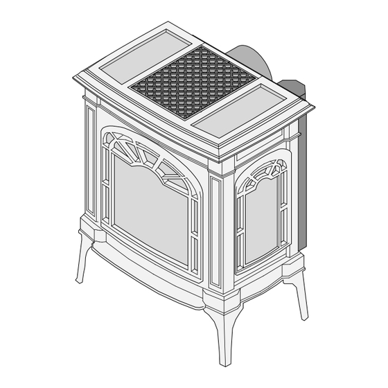
Featuring the
WARNING:
If the information in these instructions is not followed exactly, a fire or explosion
may result causing property damage, personal injury or loss of life.
-
Do not store or use gasoline or other flammable vapors and liquids in the vicinity of this or any
other appliance.
WHAT TO DO IF YOU SMELL GAS
• Do not try to light any appliance.
• Do not touch any electrical switch; do not use any phone in your building.
• Immediately call gas supplier from a neighbor's phone. Follow the gas supplier's instructions.
• If you cannot reach your gas supplier, call the fire department.
-
Installation and service must be performed by a qualified installer, service agency or the gas
supplier.
This appliance may be installed in an aftermarket permanently
located, manufactured home (USA only) or mobile home, where
not prohibited by local codes.
This appliance is only for use with the type(s) of gas indicated on
the rating plate. A conversion kit is supplied with the appliance.
Northfield
Owner's Manual
Installer:
After installation give this manual to the home-owner
and explain operation of this heater.
Copyright 2009, T.I.
Burner
$10.00
100-01239_000
• Direct Vent Freestanding Stove
• Natural Gas or Propane
• Vent Horizontally or Vertically
• Standard Residential
• Mobile Home Approved
Tested and Listed by
Omni-Test Laboratories, Inc.
Portland, Oregon
Report # 028–S–50d-5
ANSI Z21.88,
www.travisproducts.com
4800 Harbour Pointe Blvd. SW
4091120
Mukilteo, WA 98275
Advertisement
Table of Contents

Related Manuals for Travis Industries Lopi Northfield


Summary of Contents for Travis Industries Lopi Northfield
- Page 1 • Direct Vent Freestanding Stove • Natural Gas or Propane • Vent Horizontally or Vertically • Standard Residential • Mobile Home Approved Tested and Listed by Omni-Test Laboratories, Inc. Portland, Oregon Featuring the Burner Report # 028–S–50d-5 ANSI Z21.88, WARNING: If the information in these instructions is not followed exactly, a fire or explosion may result causing property damage, personal injury or loss of life.
-
Page 2: Introduction & Important Information
Introduction Introduction We welcome you as a new owner of a Lopi Northfield stove. In purchasing a Northfield you have joined the growing ranks of concerned individuals whose selection of an energy system reflects both a concern for the environment and aesthetics. The Northfield is one of the finest home heaters the world over. -
Page 3: Table Of Contents
Interior Masonry Chimney Conversion ....26 Finalizing the Installation Leak Test ............27 Pilot Adjustment (if necessary) ......27 Air Shutter Adjustment (if necessary) ....28 Check Flame ............28 Face and Glass Removal ........29 Log Installation ............ 31 © Travis Industries 4091120 100-01239_000... -
Page 4: Safety Precautions
© Travis Industries 4091120 100-01239_000... - Page 5 Always follow the instructions in this manual. • If the fiber logs become damaged, replace with Travis Industries log set. • Plug the heater into a 120V • Children and adults should grounded electrical outlet. be alerted to the hazards of...
-
Page 6: Features
This heater is shipped in natural gas (NG) configuration but may be converted to propane (LP) using the included LP conversion kit. The sticker on top of the gas control valve will verify the correct fuel. © Travis Industries 4091120... -
Page 7: Installation
Loosen the three screws holding the wire cover. Remove the wire cover and place it aside. c) Slide the switch box into place and secure with the three screws. d) Slide the wire cover into place, making sure it does not pinch any wires. Secure with the three screws. © Travis Industries 4091120 100-01239_000... -
Page 8: Packing List
Batteries (4 AA and 1 9v) • Rear Vent Flue Cover • Intake Damper Plates (2) • Exhaust Restrictor Extender Plate Installation Overview See "Vent "Clearances" Requirements" See "Gas Line Installation" See "Floor Protection Requirements" © Travis Industries 4091120 100-01239_000... -
Page 9: Installation Hints
When the stove is installed in a mobile home, it must be bolted to the floor and the appliance grounded (use the optional blower with a grounded circuit or other suitable grounding method - current ANSI/NFPA 70 or CSA C22.1). © Travis Industries 4091120 100-01239_000... -
Page 10: Top To Rear Vent Modification
See the directions below. DIFFUSER SIDE VIEW Bottom of inner Before (Stock - Position # 1) flue assembly After (Position # 2) Replace the Remove the diffuser. diffuser. © Travis Industries 4091120 100-01239_000... - Page 11 Make sure the gaskets are correctly positioned and form an air- tight seal. The flue cover with a cutout may be discarded. Use the flue cover designed for rear vent applications. © Travis Industries 4091120 100-01239_000...
-
Page 12: Heater Placement Requirements
(Minimum the rubber tips may tear. 21-1/4” wide by 15-7/8” deep). Electrical Requirements • Plug the stove into a grounded receptacle supplying a minimum 1.5 amps (120 Volts, 60 Hz, 180 watts). © Travis Industries 4091120 100-01239_000... -
Page 13: Optional Wall Switch Or Thermostat Installation
“ON” position for the thermostat (or on/off switch) to operate. Burner Circuit Wires POWER SUPPLY Black Green White Black BATTERY MAIN COMFORT TRAY BURNER CONTROL Bypass Series Thermostat or White On/Off Switch Thermostat or On/Off Switch Green Green White © Travis Industries 4091120 100-01239_000... -
Page 14: Gas Line Installation
Contact the local gas supplier if the regulator is at an improper pressure. Standard Input Pressure Natural Gas 7” W.C. (1.74 Kpa) 13” W.C. (3.23 Kpa) Propane © Travis Industries 4091120 100-01239_000... -
Page 15: Vent Requirements
• Horizontal sections require a 1/4" rise every 12" of travel • Horizontal sections require non-combustible support every three feet (e.g.: plumbing tape) © Travis Industries 4091120 100-01239_000... -
Page 16: Approved Vent Configurations
Attach the damper plates to the back wall of Remove the four screws above the firebox with the screws removed earlier. the air inlets inside the firebox. Intake Damper Plates (2) (found in the owner's pack) © Travis Industries 4091120 100-01239_000... -
Page 17: Exhaust Restrictor
(see Top to Rear Vent Configuration for details). diffuser so it is bent (position # 2). DIFFUSER SIDE VIEW Bottom of inner Before (Stock - Position # 1) flue assembly After (Position # 2) Replace the Remove the diffuser. diffuser. © Travis Industries 4091120 100-01239_000... -
Page 18: Rear Vent Configurations With Horizontal Termination And No Rise
• Use 8” Diameter Vent with a 6-5/8” to 8” adapter (increaser). We recommend using the minimum vent kit from Travis Industries (SKU 96200311). This kit contains the following components used to vent the stove through a typical exterior wall: -- 6-5/8”... - Page 19 Intake Restrictor Position #3 Min. 1' (03m) Vertical Section Required 0 feet 0 feet Horizontal Elbow Horizontal elbows are elbows placed between two horizontal sections of pipe. One 45° or 90° horizontal elbow is allowed for this configuration. © Travis Industries 4091120 100-01239_000...
-
Page 20: Rear Vent Configurations With Vertical Termination
20 feet (6m) 20 feet (6m) 15 feet (4.5m) 15 feet (4.5m) Exhaust Restrictor Position #3 Intake Restrictor Position #4 10 feet (3m) 10 feet (3m) 5 feet (1.5m) 5 feet (1.5m) 0 feet 0 feet © Travis Industries 4091120 100-01239_000... - Page 21 Do not install the intake damper plate or exhaust restrictor extender plates. High Wind Termination 46DVA-VCH Liner Termination Kit (Flashing and Adapter) 46DVA-GK 3" (77mm) Dia. Flex Lines Min. 18" Co-Axial to Co-Linear Adapter 46DVA-TCL © Travis Industries 4091120 100-01239_000...
-
Page 22: Top Vent Configuration With Vertical Termination
10 feet (3m) 5 feet (1.5m) 5 feet (1.5m) 0 feet 0 feet Horizontal Elbow Horizontal elbows are elbows placed between two horizontal sections of pipe. One 45° or 90° horizontal elbow is allowed for this configuration. © Travis Industries 4091120 100-01239_000... -
Page 23: Top Vent Configuration With Horizontal Termination
5 feet (1.5m) Min. 2' (0.61m) Rise Required 0 feet 0 feet Horizontal Elbow Horizontal elbows are elbows placed between two horizontal sections of pipe. One 45° or 90° horizontal elbow is allowed for this configuration. © Travis Industries 4091120 100-01239_000... -
Page 24: Vent Termination Requirements
NOTE: Measure clearances to the nearest edge of the exhaust hood. • Use the vinyl siding standoff when installing on an exterior with vinyl siding. • Vent termination must not be located where it will become plugged by snow or other material © Travis Industries 4091120 100-01239_000... -
Page 25: Class A Chimney Conversion
Retro Connector Screw the Retro Simpson Duravent Direct Connector to the Retro Vertical Top Vent Pipe Sections Flex Pipe (use adjustable section) Additional Required Equipment: 4" Flex (#711 or U.L. 1777) Termination (#991) Co-Axial Sections © Travis Industries 4091120 100-01239_000... -
Page 26: Interior Masonry Chimney Conversion
(or other UL 1777 Gas Liner) Make sure the coaxial pipe maintains a 1” clearance to any Connector (included in #934 combustible. The vent must be Masonry Conversion Kit) sealed air-tight. secured and sealed to block-off plate. © Travis Industries 4091120 100-01239_000... -
Page 27: Leak Test
(see the illustration below). Velcro is used to secure the 9v battery. Battery Holder AA Battery Tray Swing the control cover down to access the batteries. Battery Holder for Control Panel Lights © Travis Industries 4091120 100-01239_000... -
Page 28: Air Shutter Adjustment (If Necessary)
The flames should burn off of each burner hole. If the heater does not work correctly, contact your Travis dealer for a remedy. 11. Give this manual to the home owner for future reference and fully explain operation of this heater. © Travis Industries 4091120 100-01239_000... -
Page 29: Face And Glass Removal
Swing the glass frame into place - you may have to lift it slightly to allow it to fit over the top of the firebox. c) Attach the upper latches (follow the instructions above in reverse). d) Replace the stove front and top. © Travis Industries 4091120 100-01239_000... - Page 30 Top of Firebox Glass Frame Anchor Note how the washer on the latch fits behind the flange on the glass frame anchor. Once fully inserted, turn the latch until it is upright. © Travis Industries 4091120 100-01239_000...
-
Page 31: Log Installation
See page 45 for details on burner removal. Rear Log Placement The rear log has two holes on the bottom. Place the log so the pins on the burner insert into the holes on the log (see photos below). © Travis Industries 4091120 100-01239_000... -
Page 32: Travis Industries
(see photos below). Right Log Placement The right log has two holes on the bottom. Place the log so the two pins on the burner insert into the holes on the log (see photos below). © Travis Industries 4091120 100-01239_000... - Page 33 The right twig has two holes in the bottom that fit over the pin on the back and right log (see photos below). The lower side of the twig rests on the right log. Place the twig as shown below. © Travis Industries 4091120...
- Page 34 Use a stiff brush to apply a thin layer of rockwool fibers onto the burner. Do not use the entire bag of rockwool. Use only a small amount and save the remainder. Over-use of rockwool will diminish the glow and may cause sooting or other adverse conditions. © Travis Industries 4091120 100-01239_000...
-
Page 35: Before You Begin
Comfort Control This switch turns the rear burner on and off. This holder contains 4 AA batteries that allow the stove to operate during AA Battery Holder power outages. © Travis Industries 4091120 100-01239_000... -
Page 36: Starting The Stove For The First Time
Adjusting the Flame Height This stove has an adjustable flame to tailor the look and heat output to your specific needs. It is adjusted by turning the flame adjust knob. © Travis Industries 4091120 100-01239_000... -
Page 37: Accent Light
Frequent On / Off Operation – if you are frequently turning the stove on and off, you may wish to leave it in continuous pilot. This allows the burner to turn on more quickly, without pilot ignition delay. © Travis Industries 4091120... -
Page 38: Normal Operating Sounds
This appliance has several areas that reach high temperatures. Dust or other particles on these areas may burn and create a burnt-paper smell. This is normal during startup. You may notice the smell is more acute if the appliance was left idle for a long period. © Travis Industries 4091120 100-01239_000... -
Page 39: Maintenance
LED lights do not operate, replace the 9v battery (see the illustration below). Velcro is used to secure the 9v battery. Battery Holder AA Battery Tray Swing the control cover down to access the batteries. Battery Holder for Control Panel Lights © Travis Industries 4091120 100-01239_000... -
Page 40: Accent Light Replacement
If the pilot or main burners do not burn correctly, contact your dealer for service. Monitor blower operation. Remove any debris or vegetation near the vent termination. Contact your dealer if any sooting or deterioration is found near the vent termination. © Travis Industries 4091120 100-01239_000... -
Page 41: Troubleshooting Table
Replace the AA batteries (see page 39) Comfort Control Does not Work The logs or coals are placed incorrectly See "Log Set Installation" Thin Layer of Soot Improper air shutter adjustment Adjust Air Shutter - contact your dealer Covers the Glass © Travis Industries 4091120 100-01239_000... -
Page 42: Wiring Diagram
Warning: Do not operate appliance with the glass front removed, cracked, or broken. Replacement of the glass should be done by a licensed or qualified service person. Contact your local Travis Industries Dealer for a Replacement Parts List © Travis Industries 4091120... -
Page 43: Safety Label
Electrical Rating: 115v, 1.5 Amps, 60 Hz Optional Blower: #99000142 Manufacture 2009 Jan. Apr. Jul. Oct. Date: 2010 Feb. Aug. Nov. 4800 Harbour Pointe Blvd. SW Mukilteo, WA 98275 2011 Mar. Jun. Sep. Dec. www.travisproducts.com IGN 0847 © Travis Industries 4091120 100-01239_000... -
Page 44: Warranty
2. Travis Industries has the option of either repairing or replacing the defective component. 3. If your dealer is unable to repair your appliance’s defect, he may process a warranty claim through TRAVIS INDUSTRIES, INC., including the name of the dealership where you purchased the appliance, a copy of your receipt showing the date of the appliance’s purchase, and the serial number on your appliance. -
Page 45: Optional Equipment
1 Remove the glass (see page 29). Remove the logs and embers (if installed - page 31). 2 Remove the burner (see below). Grasp the burner with both hands and lift it straight up and out of the firebox. © Travis Industries 4091120 100-01239_000... - Page 46 Use a 1/2" open end wrench to unscrew the two orifices. Look here for the orifice identification Screw each LP orifice in so the orifice protrudes 15/16" (24mm) Front (indicating full insertion). Rear 15/16" 24mm © Travis Industries 4091120 100-01239_000...
- Page 47 T-20 Torx or Slotted Screwdriver Make the gas line connection, bleed the gas line (if applicable), start the heater and thoroughly leak- test all gas connections and the gas control valve. © Travis Industries 4091120 100-01239_000...
-
Page 48: Greensmart™ Remote Control Installation
(2) #8 x ½” Machine Screws (2) Wire Ties Torx T-20 Wrench Wall Mount (for placing the transmitter on a wall) (2) Drywall anchors (for wall mount) (2) #8 x 3/8” Type B Screws © Travis Industries 4091120 100-01239_000... - Page 49 CONTROL SPARK ROD DIAGNOSTIC ADAPTER VALVE COMMAND POWER GROUND Green Orange POWER SUPPLY Yellow / Green IPI / CPI Black Green Blue White White Black CONTINUOUS PILOT BATTERY COMFORT MAIN BURNER TRAY GREENSMART CONTROL PILOT © Travis Industries 4091120 100-01239_000...
- Page 50 Receiver IPI / CPI Blue White CONTINUOUS (4) AA Batteries PILOT FAN CONTROL Fan Controller POWER 120 VAC INTERMITTENT Power In 110V OUT AUX OUT PILOT Accent Thermodisk Light (s) Optional Blower(s) Accent Light Rheostat © Travis Industries 4091120 100-01239_000...
- Page 51 Remove the four screws holding the control panel to the front of the stove (see Figure 3). Carefully remove the control panel, making sure you do not disconnect any wiring (see Figure 4). Figure 4 Figure 3 © Travis Industries 4091120 100-01239_000...
- Page 52 Figure 6 Disconnect the two leads on the back of the control panel for the IPI / CPI switch (continuous pilot / greensmart pilot – see Figure 7). Figure 7 © Travis Industries 4091120 100-01239_000...
- Page 53 Pull the plate and wiring forward (see Figure 12). Un-hook the wires from the wire-locks and remove the wiring harness, plate, battery holder, and ac adapter (see Figure 13). These items may be discarded. Figure 13 Figure 12 © Travis Industries 4091120 100-01239_000...
- Page 54 16) – tighten to 25 Lb-inches. Leak test this area after installation to verify proper installation. Figure 16 Figure 15 11 Place the GreenSmart wiring harness in front of the stove, noting the position of each connector (see .Figure 17). Figure 17 © Travis Industries 4091120 100-01239_000...
- Page 55 13 Attach the blue and white wires to the IPI/CPI switch (see Figure 20). Connect the wiring harness to the stepper motor (see Figure 21). Figure 21 Figure 20 14 Attach the wiring harness to the comfort control valve connection (see Figure 22). Figure 22 © Travis Industries 4091120 100-01239_000...
- Page 56 17 Access the back of the stove and disconnect the power lead from accent light (see Figure 26). Connect the accent light wiring to the power lead included with this kit (see Figure 27). Figure 26 Figure 27 © Travis Industries 4091120 100-01239_000...
- Page 57 19 Slide the receiver through the control panel and attach the “RECEIVER” connector to the receiver (see Figure 29). Attach the control panel to the stove using the four screws removed earlier (see Figure 30). Figure 30 Figure 29 © Travis Industries 4091120 100-01239_000...
- Page 58 (see Figure 34 - use a paperclip to press the “PRG” button, let it beep, then press any button on the transmitter – the receiver should beep 5 times – see the operating instructions for further details). Figure 34 Figure 33 © Travis Industries 4091120 100-01239_000...
- Page 59 Use the included drywall anchors (and screws) to secure it to the wall (see Figure 37). Figure 37 25 Restore power to the stove and test operation of the remote (see the instructions included with the remote). © Travis Industries 4091120 100-01239_000...
-
Page 60: Index
Glass Installation and Removal ......29 Water on Glass (see Condensation) ....36 Hearth Requirements ........... 12 Weight ..............6 Heating Specifications ......... 6 Wiring Diagram ............ 42 Horizontal Vent Termination Requirements ..24 Yearly Service Procedure ........40 © Travis Industries 4091120 100-01239_000...
Need help?
Do you have a question about the Lopi Northfield and is the answer not in the manual?
Questions and answers