Table of Contents
Advertisement
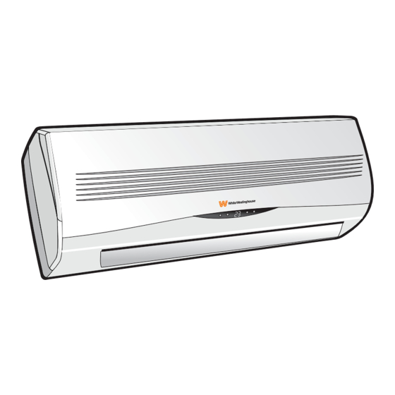
INSTRUCTIONS MANUAL
SPLIT TYPE ROOM AIR CONDITIONER
WAS(C,E)09C2ADLW / WAS(C,E)12C2ADLW / WAS(C,E)18C2ADLW
WAS(C,E)24C2ADLW / WAS(C,E)09C5ADLW / WAS(C,E)12C5ADLW
WAS(C,E)18C5ADLW / WAS(C,E)24C5ADLW / WAS(C,E)09P5ADLW
WAS(C,E)12P5ADLW / WAS(C,E)18P5ADLW / WAS(C,E)24P5ADLW
WAS(C,E)12C2ABLW
Please read this manual completely before operating your room air conditioner.
Advertisement
Table of Contents

Related Manuals for White-Westinghouse WASC09C2ADLW


Summary of Contents for White-Westinghouse WASC09C2ADLW
- Page 1 INSTRUCTIONS MANUAL SPLIT TYPE ROOM AIR CONDITIONER WAS(C,E)09C2ADLW / WAS(C,E)12C2ADLW / WAS(C,E)18C2ADLW WAS(C,E)24C2ADLW / WAS(C,E)09C5ADLW / WAS(C,E)12C5ADLW WAS(C,E)18C5ADLW / WAS(C,E)24C5ADLW / WAS(C,E)09P5ADLW WAS(C,E)12P5ADLW / WAS(C,E)18P5ADLW / WAS(C,E)24P5ADLW WAS(C,E)12C2ABLW Please read this manual completely before operating your room air conditioner.
-
Page 2: Table Of Contents
Contents Welcome to the world of simple handling and no worries. 01. Welcome....................01 Thank you for choosing White Westinghouse. This manual contains all of the 02. Environmental advices................01 information required to guarantee your safety and the appropriate use of 03. Contents....................02 your air conditioner. - Page 3 Safety precautions 16.5 Timer mode - turn off...............39 16.6 Fan mode................40 To prevent injury to the user or other people and property damage, the following instructions must be followed. 16.7 Dry mode................;40 16.8 Feel mode................41 Incorrect operation due to ignoring of instructions may cause harm or damage. 16.9 Sleep mode................42 The seriousness is classified by the following indications.
-
Page 4: Safety Precautions
7. Check that the socket is suitable for 15.Do not try to install the conditioner the plug, otherwise have the socket alone; always contact specialized changed. technical personnel. 8. Do not install the appliance at a 16.Cleaning and maintenance must be distance of less than 50 cm from carried out by specialised technical inflammable substances (alcohol,... - Page 5 22.Have repairs carried out only by an 28.The flaps must be directed authorised Service Centre of the downwards in the heating mode manufacturer . Incorrect repair and upwards in the cooling mode. could expose the user to the risk of 29.Only use the air conditioner as electric shock, etc.
-
Page 6: Prohibitions
Prohibitions 1. Do not bend , tug or compress the 8. Do not leave windows or doors power cord since this could open for long when the air damage it. Electrical shocks or fire conditioner is operating. are probably due to a damaged 9. -
Page 7: Parts List
Parts list Indoor unit Outdoor unit 1. Front panel 7. Ionizer generator(if installed) 2. Air filter 8. Deflectors 3. Optional filter (if installed) 9. Emergency button 1. Air outlet grille 4. Gas valve 4. LED Display 10. Indoor unit rating label 2. -
Page 8: Indoor Unit Instalation
Indoor unit installation Before starting installation, decide on the position of the indoor and outdoor Mounting plate units, taking into account the minimum space required around the units. Installation of the mounting plate 1. By using a level, put the mounting plate in a perfect square position vertically and horizontally. -
Page 9: Electrical Connections
Electrical connections Refrigerant piping connection Front panel 1. Lift the front panel. The piping can be run in the 3 directions indicated by numbers in the 2. Take off the cover as indicated in picture . When the piping is run in the piciure ( by removing a screw or direction 1or3, cut a notch along the by breaking the hooks). -
Page 10: Indoor Unit Condensed Water Drainage
Indoor unit condensed water After having connected the pipe drainage according to the instructions, install the connection cables. Now install the The indoor unit condensed water drain pipe. After connection,lag the drainage is fundamental for the Covered by vinyl tape pipe, cables and drain pipe with the success of the installation. -
Page 11: Outdoor Unit Instalation
Outdoor unit installation Electrical connections 1. The outdoor unit should be installed on a solid wall and fastened securely. 1. Take the cover away. 2. The following procedure must be observed before connecting the pipes and 2. Connect the cable wires to the connecting cables : decide which is the best position on the wall and leave terminal board using the same enough space to be able to carry out maintenance easily. -
Page 12: Bleeding
Operation test Installation diagram Bleeding Air and humidity left inside the refrigerant circuit can cause compressor malfunction. After having connected the indoor and outdoor units, bleed the air and humidity from the refrigerant circuit by using a vacuum pump. The air and humidity left inside the refrigerant circulation can cause compressor malfunction. -
Page 13: Indoor Unit Test
Informations Indoor unit test Fixed-speed Type Clamps 15/18k 22/24k 28/30k • Do the ON/OFF and FAN operate 1/4" 1/4" 1/4" 1/4" 3/8" 3/8" normally? Liquid pipe diameter (o6) (o6) (o6) (o6) (o9,52) (o9,52) • Does the MODE operate normally? 3/8" 3/8"... -
Page 14: Cable Wires Specification
Indoor unit display Cable wires specification 15/18k 22/24k 28/30k Fixed-speed Type sectional area 1,0mm² 2,5mm² 1,0mm² 1,0mm² 1,0mm² 4,0mm² (1,5mm²) 1,5mm² AWG14 AWG18 AWG18 AWG18 AWG12 AWG16 AWG18 H05RN-F (AWG16) 1,0mm² 2,5mm² Power supply cable 1,0mm² 1,0mm² 1,0mm² (1,5mm²) 1,5mm² 4,0mm²... -
Page 15: Display Functions
Display functions Auto-restart function Emergency function Emergency button The appliance is preset auto - restart If the remote control is lost,proceed as function by manufacturer. With this follows: Lift the unit s front panel to function the air conditioner can keep reach the emergency button of the the selected settings after a blackout or air conditioner. -
Page 16: Remote Control
Remote control How to insert the batteries When you insert the batteries for the first time in the remote control or if you Remove the cover from the battery change them, you need to program compartment , by sliding it in the the remote control of only cooling or direction of the arrow. -
Page 17: Remote Control Description
Remote control description Recommendations for locating and using the remote control (if present) The remote control may be kept in a wall-mounted holder Nº Button Function (Temp Up) Increase the temperature or time by 1 unit (Temp Dn) Decrease the temperature or time by 1 unit On/Off To switch the conditioner on and off. -
Page 18: Remote Control Display
Remote control display Nº Symbols Meaning Feel mode indicator Cooling indicator Dehumidifying indicator Fan only operation indicator Nº Button Function Heating indicator Anti-mildew To activate the function ANTI-MILDEW Signal reception indicator Display To switch on/off the LED display (if present) To switch - on /off HEALTHY funtion.It is a button which controls the Timer off indicator Healthy... -
Page 19: Modes Of Operation
Modes of operation The conditioner is designed to create the comfortable climatic conditions for the people in the room. Filter It can cool and dehumidify (and heat in models with heat pump) the air in a Heat completely automatic way. exchanger The air sucked by the fan enters from the grill of the front panel and passes... -
Page 20: Cooling Mode
Heating mode In cooling mode , orient the flaps in horizontal direction. The heating function allows the air conditioner to produce hot air. In heating mode, orient the flaps downward as the warm air always To activate the heating function (HEAT), tends to rise upward. -
Page 21: Fan Mode
Timer mode - Timer ON Fan mode To set the automatic switching-on of The conditioner works in only the air conditioner. ventilation. To program the time start,the To set the FAN mode , Press MODE appliance should be off. Press TIMER, untill (FAN ) appears in the... -
Page 22: Feel Mode
Feel mode Sleep mode Automatic mode. To activate the SLEEP mode of operation, press the SLEEP button on To activate the FEEL (automatic) mode of the remote control until the symbol operation, press the MODE button on the (AUTOQUIET) appears in the display. remote control until the symbol (FELL ) AUTO QUIET The function SLEEP... -
Page 23: Protective Device
Protective device Wiring diagram The protective device maybe trip and stop the appliance in the cases listed below. INDOOR UNIT INDOOR UNIT For T1 Climate condition models Nº Model Outdoor air temperature is over 24ºC POWER Outdoor air temperature is below -7ºC Heating SUPPLY OUTDOOR UNIT... -
Page 24: Maintenance
Maintenance Periodic maintenance is essential for Cleaning the heat exchanger keeping your air conditioner efficient. 1. Open the front panel of the unit Before carrying out any maintenance , and life it till its greatest stroke and disconnect the power supply by putting then unhooking it from the hinges the installation on/ off switch to off. -
Page 25: Troubleshooting
Solutions for problems Possible causes Malfunction Malfunction Possible causes Strange noises during operation. Switch off the air conditioner immediately Power failure/plug pulled out The appliance does not Faulty electronic control board and cut off the power operate Damaged indoor/outdoor unit fan motor supply in the event of: Faulty fuses or switches. -
Page 26: Technical Specifications
Technical specifications COOL MODELS OUTDOOR UNIT WASC12C2ABLW INDOOR UNIT WASE12C2ABLW OUTDOOR UNIT WASC09C2ADLW WASC12C2ADLW WASC18C2ADLW WASC24C2ADLW *Color INDOOR UNIT WASE09C2ADLW WASE18C2ADLW (W=White;S=Silver;M=Mirror) WASE12C2ADLW WASE24C2ADLW Cycle Cool *Color (W=White;S=Silver;M=Mirror) Cooling power (Btu/h) 12000 Cycle Cool Cool Cool Cool Heating power (Btu/h) - Page 27 Notes HEAT AND COOL MODELS OUTDOOR UNIT WASC09P5ADLW WASC12P5ADLW WASC18P5ADLW WASC24P5ADLW INDOOR UNIT WASE09P5ADLW WASE12P5ADLW WASE18P5ADLW WASE24P5ADLW *Color (W=White;S=Silver;M=Mirror) Cycle Heat/Cool Heat/Cool Heat/Cool Heat/Cool Cooling power (Btu/h) 9000 12000 18000 24000 9000 12000 18000 24000 Heating power (Btu/h) Rated voltage (V) Frequency (Hz) 1033 Indoor unit width (mm)
Need help?
Do you have a question about the WASC09C2ADLW and is the answer not in the manual?
Questions and answers