Napoleon NPS45 Installation And Operating Instructions Manual
Pellet stove heater/pellet insert heater
Hide thumbs
Also See for NPS45:
- Installation and operating instructions manual (56 pages) ,
- Maintenance & cleaning (6 pages) ,
- Installation and operating instructions manual (116 pages)
Table of Contents
Advertisement
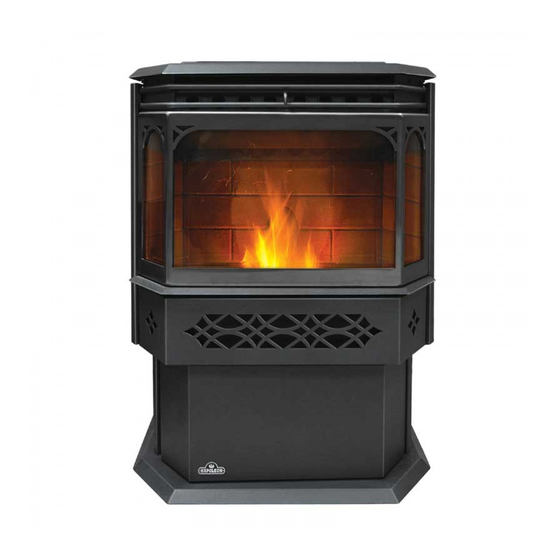
NPS45
PELLET STOVE HEATER
NPI45
PELLET INSERT HEATER
SAFETY INFORMATION
WARNING
!
PLEASE READ ENTIRE MANUAL BEFORE
YOU INSTALL OR USE THIS PELLET BURN-
ING HEATER. If the heater is not properly
installed, a house fire may result causing
personal injury or loss of life.
- Contact local building or fire officials about
restrictions and installation inspection require-
ments in your area.
- This heater is hot while in operation. Keep
children, clothing and furniture away. Contact may
cause skin burns.
- Do not start a fire with chemicals or fluids such
as gasoline, engine oil, etc...
Wolf Steel Ltd., 24 Napoleon Rd., Barrie, ON L4M 4Y8 Canada • (705)721-1212 • fax(705)722-6031
$10.00
INSTALLER: LEAVE THIS MANUAL WITH THE APPLIANCE
CONSUMER: RETAIN THIS MANUAL FOR FUTURE REFERENCE
OPERATING INSTRUCTIONS
THIS HEATER HAS BEEN TESTED TO ASTM E 1509, UL 1482, ULC S627.
www.napoleonfireplaces.com • ask@napoleon.on.ca
INSTALLATION AND
NPI45
NPS45
W415-0702 / 10.30.08
W415-0702 / 10.30.08
1
R
CM
C
US
Advertisement
Table of Contents

Related Manuals for Napoleon NPS45


Summary of Contents for Napoleon NPS45
- Page 1 INSTALLER: LEAVE THIS MANUAL WITH THE APPLIANCE CONSUMER: RETAIN THIS MANUAL FOR FUTURE REFERENCE INSTALLATION AND OPERATING INSTRUCTIONS THIS HEATER HAS BEEN TESTED TO ASTM E 1509, UL 1482, ULC S627. NPS45 PELLET STOVE HEATER NPI45 PELLET INSERT HEATER NPS45...
-
Page 2: Table Of Contents
TABLE OF CONTENTS IntroductIon WARNINGS & SAFETY PRECAUTIONS WARRANTY dImENSIONS 1.3.1 NPS45 1.3.2 NPI45 COmPlETE WITh NI800 FlAShING 1.3.3 NPI45 COmPlETE WITh Ak9 AdAPTER ANd CISk FlAShING 1.3.4 NPI45 COmPlETE WITh Ak8 AdAPTER ANd GICSk FlAShING INSTAllATION OvERvIEW General InformatIon... - Page 3 IN ThE EvENT OF A jAmmEd AUGER 10.0 normal operatInG sounds 11.0 WIrInG dIaGram 12.0 replacements 12.1 COmmON REPlACEmENT PARTS 12.2 NPS45 REPlACEmENT PARTS 12.3 NPI45 REPlACEmENT PARTS 12.4 COmmON ACCESSORY PARTS 12.5 NPI45 ACCESSORY PARTS 13.0 frequently asked questIons 14.0 troubleshootInG 15.0...
-
Page 4: Introduction
1.0 INTROdUCTION WARNINGS & SAFETY PRECAUTIONS Do Not operate the heater if you smell Before installing this heater, contact smoke coming from the heater. Turn the local building or fire authority and the Pellet Feed dial to “OFF”, monitor follow their guidelines. Notify your your heater, and call a trained insurance company of this heater as technician... - Page 5 This heater must be connected to a During a power outage this heater will standard 115 V., 60Hz grounded not operate. If a power outage does electrical outlet. Do not use an occur, check the heater for smoke adapter plug or sever the grounding spillage and open a window if any prong.
-
Page 6: Warranty
WARRANTY NAPOLEON® Pellet Heaters are manufactured under the strict Standard of the World Recognized ISO 9001 : 2000 Quality Assurance Certificate. NAPOLEON® products are designed with superior components and materials, assembled by trained crafts- men who take great pride in their work. The complete heater is thoroughly inspected by a qualified technician before packaging to ensure that you, the customer, receives the quality product that you expect from NAPOLEON®. -
Page 7: Dimensions
1.3.1 NPS45 fIGure 1.3.1b fIGure 1.3.1a 22 1/2” 26 5/8” 1 1/8” 30 1/2” 17 3/8” 11 3/4” 9 7/8” 22 3/8” 22 3/8” 1.3.2 NPI45 COmPLETE WITh NI800 FLAShING fIGure 1.3.2a fIGure 1.3.2b 38 3/8” 12 1/2” 15”... -
Page 8: Npi45 Complete With Ak9 Adapter And Cisk Flashing
1.3.3 NPI45 COmPLETE WITh Ak9 AdAPTER ANd CISk FLAShING fIGure 1.3.3b fIGure 1.3.3a 10 5/8” 16 1/2” 31” 28 1/8” Stand-offs 20 5/8” 7 5/8” 2 3/4” Center 26 1/2” line of 46 7/16” exhaust Center line of air intake 20 3/8”... -
Page 9: Npi45 Complete With Ak8 Adapter And Gicsk Flashing
1.3.4 NPI45 COmPLETE WITh Ak8 AdAPTER ANd GICSk FLAShING fIGure 1.3.4a fIGure 1.3.4b 46 7/16” 10 5/16” 15 5/8” Stand-offs 29 3/16” 20 3/8” 7 5/8” 2 3/4” Center 26 1/2” line of exhaust Center line 20 3/8” of air intake 8”... -
Page 10: Installation Overview
INSTALLATION OvERvIEW See the section “INSTALLATION - MINIMUM MANTEL CLEARANCES” fIGure 1.4 See the section Drywall “MINIMUM FRAMING (or other DIMENSIONS” combustible material) See the section See the sections “MINIMUM “GENERAL VENTING” CLEARANCES TO and “INSTALLATION” COMBUSTIBLES” Side Wall See the section “INSTALLATION INTO A BUILT-IN ENCLOSURE”... -
Page 11: General Information
2.0 GENERAL INFORmATION Thank you for purchasing the Wolf Steel Ltd. Pellet Heater. This heater is designed for use with Pelletized Wood Only. Please read this entire manual before installation and use of this pellet fuel-burning room heater. Failure to follow these instructions could result in property damage, bodily injury or even death. -
Page 12: Heating Specifications
Rate (Pounds per hour)** 1.0 to 5.0 maximum burn Time on low burn** 55 hours (NPS45), 45 hours (NPI45) hopper Capacity 55 Pounds (NPS45), 45 Pounds (NPI45) * Heating capacity will vary depending on the home's floor plan, degree of insulation, and the outside temperature. It is also affected by the fuel size, quality, and moisture level. -
Page 13: Installation Planning
If the heater is placed in a location where the ceiling height is less than 7' above the base of the heater, the installation must follow the requirements in the section "Alcove Installations Requirements". INSTALLATION OPTIONS nps45: To install in a Residential or mobile home see the section "Mobile Home Requirements". For alcove installations see the section "Alcove Installation Requirements". -
Page 14: Outside Air
OUTSIdE AIR Available from your Authorized Dealer (114KT) Outside air must not be drawn from an enclosed space (garage, unventilated crawl space). NOTE: Wolf Steel Ltd. strongly suggests using outside air for all residential installations, especially for those that are energy efficient, air-tight homes. Outside air supply must not be over 15' long. -
Page 15: General Venting
4.0 GENERAL vENTING WARNING Pellet vent must maintain a minimum 3" clearance to any combustible (install vent at clearances specified by the vent manufacturer). Do not connect the pellet vent to a vent or chimney serving any other appliance or heater. Do not install a flue damper in the exhaust venting system of this unit. -
Page 16: Minimum Air Terminal Location Clearances
mINImUm AIR TERmINAL LOCATION CLEARANCES fIGure 4.7 Illustration dimensions are to the center and the exhaust exit point of the vent. CLEARANCE Clearance above grade, veranda porch, deck or balcony. 24 INCHES (Including Vegetation and Mulch) Clearance beside or below any windows or doors that open. 48 INCHES 12 INCHES* Clearance above any window or door that opens. -
Page 17: Stove Venting Installation Examples
STOvE vENTING INSTALLATION ExAmPLES 4.6.1 ALCOvE INSTALLATION fIGure 4.6.1 minimum alcove dimensions 4.6.2 hORIzONTAL ExhAUST ThROUGh WALL INSTALLATION 3” Minimum fIGure 4.6.2 12” Minimum Wall Thimble 6” 5’ Maximum Minimum 11-3/4” Floor 17-3/8” Protection Outside Air (Recommended) Wall Thimble W415-0702 / 10.30.08... -
Page 18: Through Wall With Vertical Rise And Horizontal Termination
4.6.3 ThROUGh WALL WITh vERTICAL RISE ANd hORIzONTAL TERmINATION Wall Thimble fIGure 4.6.3 Outside Air (Recommended) 3” 2” 6” Minimum Floor Protection 4.6.4 mINImUm INSIdE vERTICAL CLEARANCES Vertical Cap Storm Collar Roof Flashing Vent must maintain 3” Ceiling Support clearance to combus- tibles. -
Page 19: Class A Chimney Retrofit
4.6.5 CLASS A ChImNEY RETROFIT Vertical Cap Storm Collar Roof Flashing Vent must maintain Class A Chimney 3” clearance to Ceiling Support combustibles. fIGure 4.6.5 3” 2” Floor Protection Outside air (Recommended) (Installation show- ing inlet of outside air in ventilated crawl space) 4.6.6 hEARTh mOUNT INSTALLATION Vertical Cap... -
Page 20: Installation Into A Masonry Heater
4.6.7 INSTALLATION INTO A mASONRY hEATER WARNING Do not remove bricks or mortar from the fireplace. Prior to installation: When installing into a masonry fireplace, do not remove any bricks or masonry. Do not weaken the structure, or reduce the protection for combustible materials to less then that required by the National Building Code. -
Page 21: Stove Installation
5.0 STOvE INSTALLATION mINImUm CLEARANCE TO COmBUSTIBLES 5.1.1 STRAIGhT INSTALLATION Interior vertical vents Through the Wall Installations fIGure 5.1.1b fIGure 5.1.1a 5.1.2 CORNER INSTALLATION Through the Wall vents Interior vertical vents fIGure 5.1.2b fIGure 5.1.2a note: If interior vertical pellet vent is used, the clearance to the back wall is determined by the upward-turning elbow or "tee". -
Page 22: Insert Installation
6.0 INSERT INSTALLATION mASONRY hEATER INSTALLATION WARNING Do not remove bricks or mortar from the fireplace. Prior to installation: Vertical Stand-offs may be removed to fit the insert into the fireplace. Storm Collar When installing the insert into a masonry fireplace, do not remove any bricks Cover Plate or masonry. -
Page 23: Factory Built (Metal) Heater Installation
FACTORY BUILT (mETAL) hEATER INSTALLATION Prior to installation: Vertical Stand-offs may be removed to fit the insert into the fireplace. Do not weaken the structure, or reduce the protection for combustible materials to less then that required by the National Building Code. Bolted or screwed together pieces Storm Collar (smoke shelf / deflectors) may be removed, but must be able to be re-installed if the... -
Page 24: Installation Into A Combustible Enclosure
INSTALLATION INTO A COmBUSTIBLE ENCLOSURE WARNING the stand-offs located on the back of the insert must not be removed when installing the insert into a built-in combustible enclosure. WARNING outside air is mandatory for a combustible built-in enclosure install. When installing the insert as a "built-in" heater, it is important to maintain the clearances to combustibles, see "mINImUm ClEARANCE TO COmbUSTIblES"... -
Page 25: Minimum Enclosure Clearances
6.3.2 mINImUm ENCLOSURE CLEARANCES WARNING the stand-offs located on the back of the insert must not be removed when installing the insert into a built-in combustible enclosure. WARNING fIGure 6.3.2 6 3/8” Minimum 2 1/4” 40” 3” all around (Refer to vent manufacturer’s instructions) 27”... -
Page 26: Minimum Mantel Clearances
6.3.4 mINImUm mANTEL CLEARANCES fIGure 6.3.4 6.3.5 REAR TO TOP vENT CONvERSION INSTRUCTIONS note: The insert is factory shipped in a rear vent configuration. Be fIGure 6.3.5 careful not to damage the gasket. exhaust cover If installing 4" diameter vent vertically, it will be necessary to start with a 12" section of 3"... -
Page 27: Insert Finishing
7.0 INSERT FINIShING FLAShING INSTALLATION fIGure 7.1.1 ● 7.1.1 Secure the Right Flashing to the right side of the heater using two of the #8 x 1/2" screws. NOTE: Feed the Air Control Rod into the Air Control Slot on the Right Flashing before securing. -
Page 28: Installing Viewing Door
INSTALLING vIEWING dOOR The main viewing door has been boxed separate from the heater, but MUST be installed before burning the heater. 7.3.1 ● Open both side panels, exposing the bushing on the left and the latches on the right. 7.3.2 ●... -
Page 29: Lighting Heater Manually
LIGhTING hEATER mANUALLY WARNING Heater may be hot. Other than placing a handful of pellets in the burn pot for lighting manually, never feed pellets through the glass viewing door. An "OVERFIRE" condition could occur, if more pellets enter the firebox than what the feed tube can deliver. -
Page 30: Control Adjustments
AUTO / T-STAT / MANUAL This switch is used to select the operating mode. MANUAL: Sliding the switch down to manual will allow you to manually select the heat and blower settings. In manual mode the heater will run at your desired settings indefinitely, until you manually turn the heater off or the heater runs out of pellets. -
Page 31: Installing A Thermostat
INSTALLING A ThERmOSTAT An optional millivolt thermostat is available to help keep the room temperature constant. NOTE: The thermostat must be installed by a qualified installer. ● Disconnect the power supply. 8.6.1 ● Remove the right side panel to gain access to the rear of the control panel. 8.6.2 ●... -
Page 32: General Maintenance
9.0 GENERAL mAINTENANCE dAILY (WhENEvER USING ThE hEATER) 9.1.1 OPEN mAIN vIEWING dOOR WARNING The front of the heater becomes very hot during operation. Let the heater cool completely before conducting service. A. Open the side doors on either side of fIGure 9.1.1a the heater. -
Page 33: Cleaning The Heat Exchanger Tubes
9.1.6 CLEANING ThE hEAT ExChANGER TUBES WARNING The front edge of the hopper lid becomes very hot, do not touch the area below the handle. This rod becomes very hot during operation. Wait till heater has cooled completely or you must wear heat resistant gloves when cleaning or handling this heater. -
Page 34: Bi-Weekly (Or Every 10 Bags Of Pellets)
BI-WEEkLY (OR EvERY 10 BAGS OF PELLETS) 9.2.1 vACUUm FIREBOx WARNING The firebox becomes very hot during operation. Let the heater cool completely before conducting service. The more frequently you clean out the fly ash, the more efficient your heater will burn. A. -
Page 35: Soot And Fly Ash Formation
9.3.2 SOOT ANd FLY ASh FORmATION The products of combustion will contain small particles of fly ash. The fly ash will collect in the exhaust venting system and restrict the flow of the flue gases. Incomplete combustion occurs during startup, shutdown, or incorrect operation of the room heater will lead to some soot formation which will collect in the exhaust venting system. -
Page 36: Check All Seals
9.3.6 ChECk ALL SEALS Check for air leaks around the door, glass, and ash pan and replace gaskets as required. Air leaks into the firebox will decrease the heater's performance greatly, leading to excessive soot, inefficient burning, and may even cause a malfunction. Test the door seal by shutting the door on a piece of paper in various locations. -
Page 37: Normal Operating Sounds
10.0 NORmAL OPERATING SOUNdS fIGure 10.0 TP - OPERATING SOUNdS_PEllET W415-0702 / 10.30.08... -
Page 38: Wiring Diagram
11.0 WIRING dIAGRAm fIGure 10.0 COMBUSTION HOPPER SWITCH LOW LIMIT VACUUM SWITCH BLOWER BLUE BLUE BLACK PURPLE BROWN BROWN AUGER POWER CONVECTION HIGH IGNITOR MOTOR CORD BLOWER LIMIT ORANGE BLACK GREY GREY BLACK YELLOW WHITE GREEN BLACK BLACK BLACK BLACK TP - WIRING dIAGRAm_PEllET W415-0702 / 10.30.08... -
Page 39: Replacements
12.0 REPLACEmENTS Contact your dealer or the factory for questions concerning prices and policies on replacement parts. Normally all parts can be ordered through your Authorized dealer / distributor. FOR WARRANTY REPLACEMENT PARTS, A PHOTOCOPY OF THE ORIGINAL INVOICE WILL BE REQUIRED TO HONOUR THE CLAIM. - Page 40 ExhAUST GASkET W010-1612 ExhAUST COllAR W010-0219 ExhAUST COvER W290-0122 ExhAUST GASkET W010-1673 RIGhT lOUvRE ASSEmblY W010-1685 lEFT lOUvRE ASSEmblY NPS45 COmPONENTS part no. descrIptIon W010-1508 WEldEd TOP ASSEmblY W010-1527 SIdE dOOR ASSEmblY W010-1529 hOPPER dOOR ASSEmblY W010-1667 ASh PAN ASSEmblY...
- Page 41 NPS45 ACCESSORIES part no. descrIptIon NPhE-40 hOPPER ExTENSION (INCREASES hOPPER CAPACITY FROm 55 lbS TO 100 lbS PEllETS) NPI45 ACCESSORIES part no. descrIptIon NI800 8" blACk FlAShING WITh blACk TRIm GICSk ARChEd CAST IRON SURROUNd AdAPTOR kIT (REq'd FOR GICSk)
-
Page 42: Common Replacement Parts
12.1 COmmON REPLACEmENT PARTS W415-0702 / 10.30.08... -
Page 43: Nps45 Replacement Parts
12.2 NPS45 REPLACEmENT PARTS W415-0702 / 10.30.08... -
Page 44: Npi45 Replacement Parts
12.3 NPI45 REPLACEmENT PARTS W415-0702 / 10.30.08... -
Page 45: Common Accessory Parts
12.4 COmmON ACCESSORY PARTS PRPP40 NPL41 12.5 NPI45 ACCESSORY PARTS NI800 W415-0702 / 10.30.08... -
Page 46: Frequently Asked Questions
13.0 FREqUENTLY ASkEd qUESTIONS Before calling a service technician, read the following guide for answers to frequently asked questions. Q. When I first light the heater, pellets were not feeding and the heater turned off? A. When first starting this heater or when you completely empty the hopper of pellets, the auger feed screw is empty. If proof of fire has not been established the heater will turn off. -
Page 47: Troubleshooting
14.0 TROUBLEShOOTING ALL TROUBLE SHOOTING PROCEDURES SHOULD BE CARRIED OUT BY QUALIFIED TECHNICIANS OR INSTALLERS. CAUTION: When checking connections, installing jumper wires (for test purposes only) or replacing components, unplug heater from the receptacle to prevent electrical shock or damage to the components. NOTE: Many of the following tests will require that the side panels are removed from the heater or the insert be removed from its cavity to access the components. - Page 48 SYMPTOM TEST SOLUTION HEATER SHUTS OFF AND THE #3 LIGHT FLASHES The hopper is out of - Refill the hopper. pellets. The hopper lid open. - Close the hopper lid. The burnpot is not - Ensure the burn pot locating notch engages with the ignitor and that the burn pot sits flat. seated completely into the burner housing.
-
Page 49: Smoke Smell Coming Back Into The Home
SYMPTOM TEST SOLUTION SMOKE SMELL COMING BACK INTO THE HOME There is a leak in - Inspect all vent pipe connections. Make sure they are sealed with RTV silicone that has a temperature the vent pipe system. rating of 500°F or higher. Also, seal joints with UL-181-AP foil tape. Also, make sure the square to round adapter piece on the combustion blower has been properly sealed with the same RTV. - Page 50 SYMPTOM TEST SOLUTION Circuit board - Time the fuel feed light at each setting (after the heater has completed the start-up cycle). If the auger malfunction. motor runs constantly, the board is defective. Bad pellets (applies - The brand of pellets or the batch of pellets that are being used may be of poor quality. If possible, try a to GLASS SOOT’S different brand of pellets.
-
Page 51: Service History
15.0 SERvICE hISTORY TP - SERvICE hISTORY W415-0702 / 10.30.08... - Page 52 NOTES TP - NOTES W415-0702 / 10.30.08...
Need help?
Do you have a question about the NPS45 and is the answer not in the manual?
Questions and answers