
Related Manuals for Provision ISR N Series


Summary of Contents for Provision ISR N Series
- Page 1 DVR User Manual N Series For H.264 4/8-channel digital video recorder All rights reserved...
- Page 2 DVR User Manual For H.264 4/8-channel digital video recorder All rights reserved...
- Page 3 Digital Video Recorder User Manual CAUTION Please read this user manual carefully to ensure that you can use the device correctly and safely We do not warrant all the content is correct. The contents of this manual are subject to change without notice This device should be operated only from the type of power source indicated on the marking label.
-
Page 4: Table Of Contents
Digital Video Recorder User Manual Table of Contents Introduction ..........................................7 1.1 DVR Introduction ....................................... 7 1.2 Main Features ........................................7 Hardware Installation ......................................10 2.1 Install Hard Drive ......................................10 2.1.1 Install Hard Drive ....................................10 2.2 Front Panel Instructions ....................................11 2.3 Rear Panel Instructions .................................... - Page 5 Digital Video Recorder User Manual 4.1 Basic configuration......................................24 4.1.1 System ........................................25 4.1.2 Time & date ......................................26 4.1.3 DST ........................................26 4.2 Live configuration ......................................27 4.2.1 Live ........................................27 4.2.2 SPOT........................................29 4.2.3 Mask ........................................30 4.3 Record configuration ......................................31 4.3.1 Enable ........................................
- Page 6 Digital Video Recorder User Manual 4.6.1 Network ......................................... 48 4.6.2 Network stream ...................................... 52 4.7 User management configuration ..................................54 4.8 P.T.Z configuration ......................................55 Record search & playback and backup ................................60 5.1 Time search ........................................60 5.2 Event search ........................................61 5.3 File manager ........................................
- Page 7 Digital Video Recorder User Manual 7.3 Remote playback & backup ....................................78 7.3.1 Remote playback ....................................78 7.3.2 Remote backup ...................................... 83 7.4 Remote System configuration ..................................84 Mobile Surveillance ......................................85 8.1 By Phones with Windows mobile ..................................85 8.2 By Phones with Symbian ....................................
-
Page 8: Introduction
Digital Video Recorder User Manual Introduction 1.1 DVR Introduction This model DVR (Digital Video Recorder) is designed specially for CCTV system. It adopts high performance video processing chips and embedded Linux system. Meanwhile, it utilizes many most advanced technologies, such as standard H.264 with low bit rate, Dual stream, SATA interface, VGA output mouse supported, IE browser supported with full remote control, mobile view(by phones), etc., which ensure its powerful functions and high stability. - Page 9 Digital Video Recorder User Manual RECORD & PLAYBACK • Record modes: Manual, Schedule, Motion detection and Sensor alarm recording • Support recycle after HDD full • Resolution, frame rate and picture quality are adjustable • 128MB for every video file packaging •...
- Page 10 Digital Video Recorder User Manual • Support 1 administrator and 15 users. • Support event log recording and checking, events unlimited NETWORK • Support TCP/IP, DHCP, PPPoE, DDNS protocol • Support IE browser to do remote view • Support setup client connection amount •...
-
Page 11: Hardware Installation
Digital Video Recorder User Manual Hardware Installation Notice: Check the unit and the accessories after getting the DVR. Please disconnect the power before being connected to other devices. Don't hot plug in/out 2.1 Install Hard Drive 2.1.1 Install Hard Drive Notice: 1. -
Page 12: Front Panel Instructions
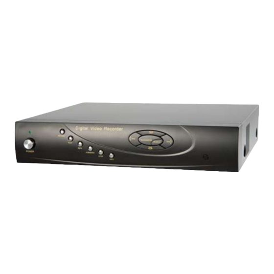
Digital Video Recorder User Manual Fig 2.2 Screw HDD 2.2 Front Panel Instructions Notice: The front panel descriptions are only for reference; please make the object as the standard. Type Item Name Description Power Power indicator, when connection , the light is blue When HDD is writing and reading , the light is blue When access to network , the light is blue Work state indicator... -
Page 13: Rear Panel Instructions
Digital Video Recorder User Manual Item Type Name Description 1. Rewind key REW/SPEED 2. SPEED function enables at PTZ mode 1. Enter search mode SEARCH/ZOOM 2.ZOOM function enables at PTZ mode. 1. Enter play interface PLAY /IRIS 2. IRIS function enables at PTZ mode 1. - Page 14 Digital Video Recorder User Manual Fig 2.3 Rear Panel for 4-ch Item Name Description Video out Connect to monitor Connect to monitor as an AUX output channel by channel. Only Spot out video display, no menu show Audio out Audio output, connect to the sound box Video in Video input channels from 1-4 DC12V...
- Page 15 Digital Video Recorder User Manual Item Name Description ALARM OUT 1-ch relay output. Connect to external alarm + 5V and GND +5 V and Grounding ALARM IN Connect to external sensor1-4 Audio in 4 CH Audio input Tab 2.1 Definitions of Front Panel Buttons The rear Panel interface for 8-ch is shown as Fig 2.4: Fig 2.4 Rear Panel for 8-ch Item...
-
Page 16: Remote Controller
Digital Video Recorder User Manual Item Name Description Video in Video input channels from 1-8 DC12V POWER INPUT VGA port VGA output, connect to monitor Network port USB port Connect USB mouse or connect external USB devices Connect to speed dome Connect to keyboard ALARM OUT 1-ch relay output. - Page 17 Digital Video Recorder User Manual Fig 2.6 Remote Controller Item Name Function Power Button Soft switch off to stop firmware running. Do it before power off. INFOR Button Get information about the DVR like firmware version, HDD information REC Button To record manually Digital Button Input digital or choose camera...
-
Page 18: Control With Mouse
Digital Video Recorder User Manual Item Name Function BACKUP Button To enter backup mode To control PTZ camera: PTZ Control Button Move camera/ZOOM/FOCUS/IRIS/SPEED control Operation processes with remote controller to control multi-DVR The device ID of the DVR is 0. When use of remote controller to control single DVR, it’s not necessarily to reset the device ID, user can do operation directly;... - Page 19 Digital Video Recorder User Manual In setup: Click left button to enter. Click right button to cancel setup, or return to the previous. If want to input the value, move cursor to the blank and click. An input window will appear as Fig2.7. It supports digitals, letters and symbols input. Fig 2.7 Digital Numbers and Letters Input Window Users can change some value by the wheel, such as time.
-
Page 20: Basic Function Instruction
Digital Video Recorder User Manual Basic Function Instruction 3.1 Power On/Off Before you power on the unit, please make sure all the connection is good. 3.1.1 Power on Step1: connect with the source power; switch on the power button near the power port in the rear panel Step2: the device will be loaded, and the power indicator will display blue Step3: before start, a WIZZARD dialogue box will be pop-up (refer to below picture) and show some information about time zone and time setup. -
Page 21: Power Off
Digital Video Recorder User Manual 3.1.2 Power off User can power off the device by using remote controller、keyboard and mouse. By remote controller: Step1: press Power button, the Shut down window will appear, click OK, the unit will power off after a while. Step2: disconnect the power By keyboard and mouse: Step1: enter into... -
Page 22: Live Preview
Digital Video Recorder User Manual 3.3 Live preview Fig 3-2 live preview interface The explanation of symbol in the live preview interface: symbol meaning symbol meaning Green Manual record or time record Alarm record Yellow Motion detection record Figure icon Move event 3.3.1 Live playback Click Play... - Page 23 Digital Video Recorder User Manual Fig 3-3 live playback...
-
Page 24: Main Menu Setup Guide
Digital Video Recorder User Manual Main menu setup guide Click right mouse or press ESC button on the front panel, the control bar will display on the bottom of the screen, refer to Fig 4-1: Fig 4-1 main menu toolbar Click the icon beside the screen display mode, a channel select dialog will appear as below: Take 8-channel DVR for example: user can tick off channels form 1-ch to 8-ch at random to display the live pictures, 6 channels can be selected... -
Page 25: Basic Configuration
Digital Video Recorder User Manual Fig 4-2 system setup Click Setup icon will pop-up the configuration menu: 4.1 Basic configuration Basic configuration includes three sub menus: system、date& time and DST. -
Page 26: System
Digital Video Recorder User Manual 4.1.1 System Step1: enter into system configuration basic configuration system; refer to Fig 4-3: Fig 4-3 basic configuration-basic Step2: in this interface user can setup the device name, device ID, video format, max network users, VGA resolution and language. The definitions for every parameters display as below: Device name: the name of the device. -
Page 27: Time & Date
Digital Video Recorder User Manual Max network uses: set the max user amount of network connection VGA resolution: the resolution of live display interface, range from: VGA800*600、VGA1024*768、VGA1280*1024and CVBS Note: : : : When switch between VGA and CVBS will change the menu output mode, please connect to relevant monitor. Language: setup the menu language. -
Page 28: Live Configuration
Digital Video Recorder User Manual Fig 4-5 basic configuration-DST Step2: in this interface, enable daylight saving time, time offset, mode, start & end month/week/date, etc. Step3: click “default” button to resort default setting; click “apply” button to save the setting; click “exit” button to exit current interface. 4.2 Live configuration Live configuration includes four submenus: live, host monitor, SPOT and mask. - Page 29 Digital Video Recorder User Manual Fig 4-6 live configuration live Step2: tick off camera name; click “setting” button, a window will pop-up as Fig 4-7: Fig 4-7 live-color adjustment...
-
Page 30: Spot
Digital Video Recorder User Manual Step3: in this interface, user can adjust brightness, hue, saturation and contrast in live; click “default” button to resort default setting, click “OK” button to save the setting. Step4: user can setup all channels with same parameters, tick off “all”, then do relevant setup. Step5: click “default”... -
Page 31: Mask
Digital Video Recorder User Manual 4.2.3 Mask User can setup private mask area on the live image picture, max threes areas. Fig 4-9 live configuration-mask Setup mask area: click Setting button, enter into live image to press left mouse and drag mouse to set mask area, refer to below picture. Click Apply button to save the setting. -
Page 32: Record Configuration
Digital Video Recorder User Manual Setup mask area Live image mask area 4.3 Record configuration Record configuration includes five sub menus: enable, record bit rate, time, recycle record and stamp. -
Page 33: Enable
Digital Video Recorder User Manual 4.3.1 Enable Step1: enter into system configuration record configuration enable; refer to Fig 4-10: Fig 4-10 record configuration-enable Step2: tick off record, audio and record time Step3: user can setup all channels with same parameters, tick off “all”, then to do relevant setup. Step4: click “default”... -
Page 34: Record Stream
Digital Video Recorder User Manual 4.3.2 Record stream Step1: enter into system configuration record configuration record bit rate; refer to Fig 4-11: Fig 4-11 record configuration-record bit rate Step2: setup rate, resolution, quality Step3: user can setup all channels with same parameters, tick off “All”, then to do relevant setup. Step4: click “default”... -
Page 35: Time
Digital Video Recorder User Manual Definitions and descriptions of Record stream: Parameter Meaning Range from: 1-30(NTSC)1-25(PAL) Rate Resolution Support CIF and D1 Quality The quality of recorded images. The higher the value is, the clearer the recorded image is. Six options: lowest, lower, low, medium, higher and highest. 4.3.3 Time Step1: enter into system configuration record configuration time;... -
Page 36: Recycle Record
Digital Video Recorder User Manual Expire time: the hold time of saved records. If the set date is overdue, the record files will be deleted automatically. Step2: user can setup all channels with same parameters, tick off “all”, then to do relevant setup. Step3: click “default”... -
Page 37: Schedule Configuration
Digital Video Recorder User Manual Step2: tick off camera name, time stamp; click Set button, user can use cursor to drag the camera name and time stamp in random positions, refer to below Figures: Before drag after drag Step3: user can setup all channels with same parameters, tick off “all”, then to do relevant setup. Step4: click “default”... - Page 38 Digital Video Recorder User Manual Fig 4-14 schedule configuration-schedule Step2: select channel, double-click and a dialog box will pop-up as Fig 4-15, user can edit week schedule: Fig 4-15 schedule-week schedule...
-
Page 39: Motion
Digital Video Recorder User Manual ① Click “add” button to add a certain day schedule; click “delete” button to delete the selected schedule; Copy: user can copy the specify schedule to other dates. Click “OK” button to save the setting, click “Exit” button to exit current interface. ①... -
Page 40: Sensor
Digital Video Recorder User Manual 4.4.3 Sensor Step1: enter into system configuration schedule configuration alarm; refer to Fig 4-17: Step2: the setup steps of alarm are familiar with schedule; user can refer to 4.4.1 Schedule for details. Note: the default schedule of sensor is full-selected, that is, the color of schedule setting interface is blue. Fig 4-17 schedule configuration-sensor 4.5 Alarm configuration Alarm configuration includes five sub menus: sensor, motion, video loss, other alarm and alarm out. - Page 41 Digital Video Recorder User Manual Fig 4-18 alarm configuration-sensor-basic Step2: enable sensor alarm, set the alarm type according to triggered alarm type. Two option: NO and NC. Step3: user can setup all channels with same parameters, tick off “all”, then to do relevant setup. Step4: click “default”...
- Page 42 Digital Video Recorder User Manual Fig 4-19 alarm configuration-sensor-alarm handling Step2: select hold time, click Trigger button, and a dialog box will pop-up as Fig 4-20: Fig 4-20 alarm handling-trigger Step3: tick off Buzzer, there will be triggered buzzer alarm out; Full screen alarm: when triggered alarm, there will pop up full screen alarm;...
- Page 43 Digital Video Recorder User Manual button to exit the current interface. To record: tick off recoding channels, it will record the camera when alarm triggered. Click OK button to save the setting; click Exit button to exit the current interface. To P.T.Z: set linked preset and cruise for alarm.
-
Page 44: Motion
Digital Video Recorder User Manual 4.5.2 Motion Motion includes two sub menus: motion and schedule. ① Motion Step1: enter into system configuration alarm configuration motion; refer to Fig 4-22: Fig 4-22 alarm configuration-motion Step2: enable motion alarm, set alarm hold time which means time interval between two adjacent detective motions. If there is other motion detected during the interval period which is considered continuous movement;... - Page 45 Digital Video Recorder User Manual Fig 4-23 motion-area Step5: in the Area interface, user can drag slide bar to set the sensitivity value (1-8), the default value is 4. The higher the value is the higher sensitivity you get. Due to the sensitivity is influenced by color and time (day or night), user can adjust its value according to the practical conditions;...
-
Page 46: Video Loss
Digital Video Recorder User Manual Step6: user can setup all channels with same parameters, tick off “all”, then to do relevant setup. Step7: click “default” button to resort default setting; click “apply” button to save the setting; click “exit” button to exit current interface. ①... -
Page 47: Other Alarm
Digital Video Recorder User Manual Fig 4-25 alarm configuration-video loss Step2: the setup steps of video loss trigger are familiar with alarm handling; user can refer to Chapter 4.5.1 Sensor alarm handling for more details. Step3: user can setup all channels with same parameters, tick off “all”, then to do relevant setup. Step4: click “default”... -
Page 48: Alarm Out
Digital Video Recorder User Manual Step1: enter into system configuration other alarm; refer to Fig 4-26: Step2: select a hard disk in the pull down list box, when the disk capacity is lower than that value, there will appear some text information on the lower right of the live image. -
Page 49: Network Configuration
Digital Video Recorder User Manual Note: the default schedule of motion detection is full-selected, that is, the color of schedule setting interface is blue. ① Buzzer Step1: enter into system configuration buzzer; Step2: tick off Buzzer, set buzzer alarm hold time 4.6 Network configuration Network configuration includes two submenus: network and network stream. - Page 50 Digital Video Recorder User Manual Step2: HTTP port: the default value is 80. If the value changed, user needs to add the port number when typing IP address in IE address blank .i.e. set HTTP port to 82, IP address: http://192.168.0.25, user needs to input that address: http://192.168.0.25:82 into IE browser.
- Page 51 Digital Video Recorder User Manual Fig 4-29 Register dialog box (2) Login Step 1: Return to homepage after registering successfully. Step 2: Click "Account Manager" on the right of homepage to login. Step 3: Input the username and password with the information that you have registered. Step 4: Click "Enter"...
- Page 52 Digital Video Recorder User Manual Fig 4-30 Log in (3) Domain Setup Step 1: Click "Domain Management" on the left to set the domain. Fig 4-31 Domain setup Step 2: Input the domain in the textbox. For example, you set DVR as the domain. Step 3: Click "Submit"...
-
Page 53: Network Stream
Digital Video Recorder User Manual server name, user name and password. Click Save button to save the setting. ① Enter into configuration interface of the router, map the server port and IP address. Click Save button to save the setting ①... - Page 54 Digital Video Recorder User Manual Fig 4-32 network configuration-sub stream Step2: select fps, resolution, quality Step3: user can setup all channels with same parameters, tick off “all”, then to do relevant setup. Step4: click “default” button to resort default setting; click “apply” button to save the setting; click “exit” button to exit current interface. Definitions and descriptions of network stream: Parameter Meaning...
-
Page 55: User Management Configuration
Digital Video Recorder User Manual Quality The quality of the clients’ image. The higher the value is, the clearer the record image. Six options: lowest, lower, low, medium, higher and highest. 4.7 User management configuration Step1: enter into system configuration user management configuration; refer to Fig 4-33: Fig 4-33 user management configuration Step2: click Add button, a dialog box will pop-up as Fig 4-34: Fig 4-34 add-general... -
Page 56: Configuration
Digital Video Recorder User Manual ① General: Input user name, password; select user type: normal and advance, input the MAC address of the PC; click OK button, this user will be added into the user list box; click Exit button to exit the current interface. Note: when the default value of binding PC MAC address is 0, the user is not bind with the specify computer;... - Page 57 Digital Video Recorder User Manual Step3: user can setup all channels with same parameters, tick off “all”, then to do relevant setup. Step4: click “default” button to resort default setting; click “apply” button to save the setting; click “exit” button to exit current interface. Definitions and descriptions of network stream: Parameter Meaning...
- Page 58 Digital Video Recorder User Manual Step2: in the Advance interface, click preset “Setting” button, a dialog box will pop-up as Fig 4-37: Fig 4-37 advance-preset setting a. in the preset set interface, click Setting button, a dialog will pop-up as Fig 3-38: Fig 3-38 preset set-setting b.
- Page 59 Digital Video Recorder User Manual d. in the preset interface, click OK button to save the setting; click Exit button to exit current interface. Step3: in the Advance interface, click cruise “Setting” button, a dialog box will pop-up as Fig 4-39: Fig 4-39 cruise set a.
- Page 60 Digital Video Recorder User Manual b. click Add icon to set the speed and time of preset point; select a preset point, click Delete icon to delete that preset point; click Modify icon to modify the setting of a preset point. User can click those icons to adjust the position of preset point.
-
Page 61: Record Search & Playback And Backup
Digital Video Recorder User Manual Record search & playback and backup Search configuration includes three submenus: time search, event search and file manager. 5.1 Time search Step1: enter into Search configuration time search; refer to Fig 5-1: Fig 5-1 Search configuration-time search Step2: select channel, screen display mode, the highlight date in the calendar means have record data Step3: select a date, press Search button, click the time grid to set the play start time or input play record time manually. -
Page 62: Event Search
Digital Video Recorder User Manual Playback buttons Note: when the monitor resolution is VGA800*600, the time search interface will appear a hide button, click this button, the whole interface can be expanded. 5.2 Event search Step1: enter into Search configuration event search; refer to Fig 5-2: Fig 5-2 Search configuration-event search... -
Page 63: File Manager
Digital Video Recorder User Manual Step2: click Search button, the searched event information will displayed in the event list box, user can select date, channel, tick off Motion, Sensor or All accordingly. Step3: double check a certain record file to playback. Note: when the monitor resolution is VGA800*600, the event search interface will appear a hide button, click this button, the whole interface can be expanded. -
Page 64: Backup
Digital Video Recorder User Manual Step3: tick off “All” button; user can lock/unlock or delete all files in the file manager column. Step4: double click an unlocked item to playback. Note: when the monitor resolution is VGA800*600, the file manager interface will appear a hide button, click this button, the whole interface can be expanded. - Page 65 Digital Video Recorder User Manual Fig 5-5 backup information Step4: in the backup information interface, user can check the relevant information of backup files, storage type, save file type, etc. click Apply button to starting backup. Note: when the monitor resolution is VGA800*600, the file manager interface will appear a hide button, click this button, the whole interface can be expanded.
-
Page 66: Manage Dvr
Digital Video Recorder User Manual Manage DVR 6.1 Check system information Check system information includes five submenus: system, event, log, network and online user. 6.1.1 System information In this interface, user can check the hardware version, MCU version, kernel version, device ID, etc. refer to Fig 6-1: Fig 6-1 system information 6.1.2 Event information In this interface, user can check record events according to set date;... -
Page 67: Log Information
Digital Video Recorder User Manual Fig 6-2 event information 6.1.3 Log information In this interface, user can check relevant log information according to set date; refer to Fig 6-3: Fig 6-3 log information... -
Page 68: Network Information
Digital Video Recorder User Manual 6.1.4 Network information In this interface, user can check relevant parameters of network; refer to Fig 6-4: Fig 6-4 network information 6.1.5 Online information In this interface, user can check the details of the current connection of online users; refer to Fig 6-5: Fig 6-5 online information... -
Page 69: Manual Alarm
Digital Video Recorder User Manual 6.1.6 Manual alarm In this interface, user can check the relevant parameters of manual alarm; refer to Fig 6-6: Fig 6-6 manual alarm 6.1.7 Disk manager Step1: enter into disk manager interface; refer to Fig 5-7: Fig 6-7 disk manager Note: please format the hard disk before record. -
Page 70: Upgrade
Digital Video Recorder User Manual Step2: click Refresh button to refresh the disk information of the list box; set the property of the disk then click Apply button to save the setting Step3: checked a hard disk, click Format button to star format. Note: all recorded files in the hard disk will be lost after formatted. -
Page 71: Remote Surveillance
Digital Video Recorder User Manual Remote Surveillance 7.1 Accessing DVR If making remote view, the DVR must connect with LAN or internet. Then enable network server in the unit. Please refer to 4.6 Network Configuration. This unit supports IE browser, not any client software installed. In addition, it supports XP and Vista. 7.1.1 On LAN Step1: Input IP address, Subnet, Gateway. - Page 72 Digital Video Recorder User Manual Fig 7.1 View with IE browser Notice: If HTTP port is not 80, other number instead, need add the port number after IP address. For example, set HTTP port as 82, need input IP address like 192.168.0.25:82. User name and password here are the same with that used on the DVR.
-
Page 73: On Wan
Digital Video Recorder User Manual 7.1.2 On WAN There are two ways that the DVR is connected to internet. 1. Connect the DVR to internet through a router or virtual server. Step1: Input IP address, Subnet, Gateway. If using DHCP, please enable DHCP in both the DVR and router. Step2: Enter Video to set network video parameters like resolution, frame rate etc. -
Page 74: The Remote Live Preview Interface As Below
Digital Video Recorder User Manual 7.2 The remote live preview interface as below: Fig 7-2 Remote live preview interface Symbol and function Definitions:... - Page 75 Digital Video Recorder User Manual ① ② ③ Channel indicator Screen display mode volume ④ ⑤ ⑥ Snapping picture Start record Playback ⑦ ⑧ ⑨ Master/sub stream Color adjustment PTZ control status Note: click button to record manual and the record file will be saved in user’s PC. Screen display mode: Click the icon beside the screen display mode, channel select dialog will appear as below:...
- Page 76 Digital Video Recorder User Manual Fig 7-4 Single snap User can multiple pictures , select the picture number from Frame pull down list box, such as 3, tick off “Title” and “Time”, it will show capture title and time on the snap pictures simultaneously. Refer to Fig 6-5: Fig 7-5 Multi-picture snap Click “Browse”...
- Page 77 Digital Video Recorder User Manual Color adjustment: Drag the slide bar to adjust Brightness, Contrast, Hue, and Saturation. Click Default to reset them to original value. Description Buttons Drag the scroll bar to adjust the brightness of channel Drag the scroll bar to adjust the contrast of channel Drag the scroll bar to adjust the saturation of channel Drag the scroll bar to adjust the hue of channel Click this button to recover the default value of brightness, contrast, saturation and hue.
- Page 78 Digital Video Recorder User Manual 'Zoom' button. Click button near 'Zoom' button to zoom in the locale picture of this camera. Click button near 'Zoom' button to zoom out the locale picture of this camera. 'Focus' button. Click button near 'Focus' button to have long focus. Click button near 'Focus' button to have short focus.
-
Page 79: Remote Playback & Backup
Digital Video Recorder User Manual 7.3 Remote playback & backup 7.3.1 Remote playback Click button to enter into record playback interface, refer to Fig 7-7: Select the record date and channels; double-click the file name in the record file list box, user can play that file and preview the picture. Fig 7-7 Play record file interface... - Page 80 Digital Video Recorder User Manual This DVR supports remote time search, event search and file management. By Time Search: Step1: Enter into Search time search; refer to Fig 7-8: Fig 7-8 time search interface Step2: click “Search” button. The record data will be displayed in the data information list box; the highlight date in the area② means have record...
- Page 81 Digital Video Recorder User Manual data, click those data; select the record channels in area③ Step3: User can set the data playing time and display mode in the area① as required Step4: Select certain item from the data information list box, click “play” button to playback Step5: Click the relevant buttons in the interface;...
- Page 82 Digital Video Recorder User Manual By Event Search: Step1: Enter into Search event search; refer to Fig 7-10: Fig 7-10 event search interface Step2: click the highlight date and select record channels and then tick off the event type: motion and sensor, click “search” button Step3: the events will be display in the event list box, double-click certain item to playback...
- Page 83 Digital Video Recorder User Manual File Management Step1: Enter into Search file management; refer to Fig 7-11: Fig 7-11 file management interface Lock: select certain file item in the file list box, click “Lock” button to lock this file that ca not be deleted or overlaid Unlock: select a locked file, click “unlock”...
-
Page 84: Remote Backup
Digital Video Recorder User Manual 7.3.2 Remote backup Click Backup button to enter into backup interface, refers to Fig 7-12: Fig 7-12 remote backup interface Step1: select channels, set the start and end time, then click “search’ button, the file information will be displayed in the file list box Step2: select backup files, click “browse”... -
Page 85: Remote System Configuration
Digital Video Recorder User Manual 7.4 Remote System configuration User can remote setup the parameters of the device. Functions of remote configurations include: basic configuration, live configuration, record configuration, schedule configuration, alarm configuration, network configuration, PTZ configuration and user configuration. User should firstly select an item in the menu list on the left, and then setup the relative parameters. -
Page 86: Mobile Surveillance
Digital Video Recorder User Manual Mobile Surveillance This DVR supports mobile surveillance by Iphone, Gphone or smart phones with Windows mobile and symbian OS. At the same time, it supports 3G network. We tested Dopod D600 (WM5) and Dopod S1 (WM6), which work fine with the DVR. It wants to make mobile surveillance, need first enable network service on the DVR, and refer to Chapter 4.6 Network configuration. - Page 87 Digital Video Recorder User Manual Step3: : : : Click “Yes” to start downloading and installing: Step4: : : : PCam will be opened automatically after installed...
- Page 88 Digital Video Recorder User Manual Step5: Input the server’s address, ID and password respectively in the columns of “Server”, “User” and “Password”, and click “Go” to log on the server. It will show the picture if access successfully. Step6: Camera 1 is the default channel after login. Change the channel in rolling-down menu of “Channel”: Notice: User name and password here are the same with that used on the DVR.
-
Page 89: By Phones With Symbian
Digital Video Recorder User Manual 8.2 By Phones with Symbian Please use the smart phones with symbian version supported by this unit. Step1: Firstly enable the network access on mobile phone. Then run Web browser. Step2: Input the DVR server’s IP address in a new-built bookmark. Click this bookmark to connect to the DVR. Step3:... - Page 90 Digital Video Recorder User Manual Live view: to do mobile live view Image view: to check the pictures snapped in live view System setting: Login setting and Alarm setting. Help: function indication and help Step7: Click System setting--->Login Setting to enter login interface.
- Page 91 Digital Video Recorder User Manual Step8: Input the server’s address, ID and password respectively. Then save. Notice: About Access point, there may be different access points in different countries or from service providers. Step9: Enter Live View, it will connect the server and display pictures. Notice: User name and password here are the same with that used on the DVR.
-
Page 92: The Operation Method For Iphone Mobile Clients
Digital Video Recorder User Manual 8.3 The operation method for iPhone mobile clients At present, the software only supports version of iPhone os2.2 and above, if phone firmware lower than this version please upgrade it. Below is the operation method for iPhone mobile clients: Step1:Enter into App Store function of iPhone function to search “SuperCam”, the required programs will be displayed on the top of search box Step 2: Enable “search”... - Page 93 Digital Video Recorder User Manual Step 3: Click SuperCam, enter into “introduce” interface and click FREE”, it will change into “INSTALL” Step 4: Enter into iTunes Store password, click “OK”will display below interface Note: if it was the first time for user to operate please enter into user ID; if there is no Store account, user need to apply one. Step 5: Just be patient to download and install.
- Page 94 Digital Video Recorder User Manual Step 6: Click “System setting”, enter into login interface. Enter into server’s IP address (or domain name), user’s ID and password. Click Back to save. Step 7: Click Live View, the default Cam1 picture will be displayed. Click to capture picture.
- Page 95 Digital Video Recorder User Manual Step 8: On function interface, click Image View to view the captured picture. Click to switch to next or previous picture. Click delete the current picture. Iphone help...
- Page 96 Digital Video Recorder User Manual Pic1 Pic2 Pic3 Live View After successfully installed SuperCam software, Click on System Setting (Pic 1), and then input Server IP address or Domain, User name and password to log in (Pic 2). If connected successfully, it will go to Live View of CH1 as default (Pic 3), please choose other desired channels from channel button underneath.
- Page 97 Digital Video Recorder User Manual Image View Pic 4 Pic 5 Item Buttons Explanations Item Buttons Explanations Item Buttons Explanations Previous picture Next Picture The first Picture The last picture Delete Search Pictures, search page as Pic 5...
-
Page 98: Appendix A Faq
Digital Video Recorder User Manual Appendix A Q1. Why the DVR cannot start after connected to the power? a. The adapter has been damaged. Please change an adapter b. The power of the adapter is not enough. Please remove the HDD to check c. - Page 99 Digital Video Recorder User Manual Q5. Cannot record a. Don't format HDD. Please format it manually first. b. Don't enable record function or incorrect setup. Please refer to Chapter 5 Record search & playback and backup. c. HDD is full and not enables recycle function. Please refer to 4.3 Record configuration. Chang a new HDD or enable recycle. d.
- Page 100 Digital Video Recorder User Manual ③ Enable all the sub options under “ActiveX controls and plug-ins” refer to Fig 7-2 ④ Then click ok to finish setup. b. Other plug-ins or anti-virus block ActiveX. Please uninstall or close them. Fig7-1 Fig7-2 Q8: How to deal with when DVR starts, it displays “please wait…”all the time First possible reason: hard-disk cable and data cable are not well connected.
- Page 101 Digital Video Recorder User Manual Second possible reason: It is forced to stop because hard disk has disabled track which causes the system checking hard disk cannot skip Solution: Change another new hard disk or reformat the broken one Q9: How to input password and digital numbers The method to input password and digital numbers is to click the box behind password or items needing to input by numbers, and then the small keyboard will appear.
- Page 102 Digital Video Recorder User Manual Motherboard Intel 845 512M NVIDIA GeForce MX440/FX5200 ATIRADEON 7500/X300 Windows 2000(SP4 above) /Windows XP(SP2 above) /VISTA DirectX Q13: What are the PC configurations for 16-ch real time product with fully open channel mainstream? PC Module Parameters Intel Core(TM)2 Duo CPU E4600 Motherboard...
- Page 103 Digital Video Recorder User Manual b. Right click IE browser (refer to Fig 14-2), select Run as administrator to run browser.
-
Page 104: Appendix B Calculate Recording Capacity
Digital Video Recorder User Manual Appendix B Calculate Recording Capacity Users can calculate the size of hard disk according to the saving time and DVR recording settings. The DVR uses fixed video bit rate. The below are the details at different settings. Frame Rate Video Format... -
Page 105: Appendix C Compatible Devices
Digital Video Recorder User Manual Appendix C Compatible Devices 1. Compatible USB drive after test. Brand Capacity 512MB, 1G, 2GB Netac Kingston Aigo Smatter vider SanDisk Tab C.1 Compatible USB drive... -
Page 106: Appendix D 4-Ch Dvr Specifications
Digital Video Recorder User Manual Appendix D 4-CH Specifications Compression format Standard H.264 Baseline Composite:1.0V p-p/75 ,BNC×2 , VGAX1 Video output Composite:1.0V p-p/75 ,BNC×4 Video input VGA Resolution 1280*1024 /1024*768/ 800*600 Record Resolution 352*288/704*576 (PAL), 352*240/704*480(NTSC) Display Frame Rate 100FPS (PAL), 120FPS (NTSC) Record Frame Rate 100FPS (PAL),... -
Page 107: Appendix E 8-Ch Dvr Specifications
Digital Video Recorder User Manual Appendix E 8-CH Specifications Compression format Standard H.264 Baseline Composite:1.0V p-p/75 ,BNC×2 , VGAX1 Video output Composite:1.0V p-p/75 ,BNC×8 Video input VGA Resolution 1280*1024 /1024*768/ 800*600 Record Resolution 352*288/704*576 (PAL), 352*240/704*480(NTSC) Display Frame Rate 200FPS (PAL), 240FPS (NTSC) Record Frame Rate 200FPS (PAL),... - Page 108 Digital Video Recorder User Manual...
Need help?
Do you have a question about the N Series and is the answer not in the manual?
Questions and answers