Table of Contents
Advertisement
Advertisement
Table of Contents

Related Manuals for Dennis FT 430


Summary of Contents for Dennis FT 430
-
Page 1: Instruction Manual
FT RANGE FINE TURF CASSETTE MOWER INSTRUCTION MANUAL DENNIS, Ashbourne Road, Kirk Langley, Derby, DE6 4NJ, United Kingdom Telephone:- 01332 824777 Fax:- 01332 824 525 E-mail:- sales@dennisuk.com E-mail:- spares@dennisuk.com SP20001_REV_2 www.dennisuk.com 02/10... -
Page 3: Declaration Of Conformity
ENGINE SERIAL NUMBER Introduction The reliability and quality of performance of the DENNIS FT depends upon some simple care maintenance carried out regularly. This manual has been prepared to allow the user to carry out all such work. It is advisable to read the instructions carefully. Proper care and attention will enable the machine to give a continuous, satisfactory, and reliable service. -
Page 4: Table Of Contents
Contents Page Product Application Matrix ..............................2 Declaration of Conformity ..............................3 Serial Numbers ..................................3 Introduction ................................... 3 Technical Data ..................................4 Machine Description ................................5 Important Safety Instructions ..............................6 Operating Instructions ..............................7 - 8 General Adjustments ..............................9 - 11 Removing The Cassette Unit .............................. -
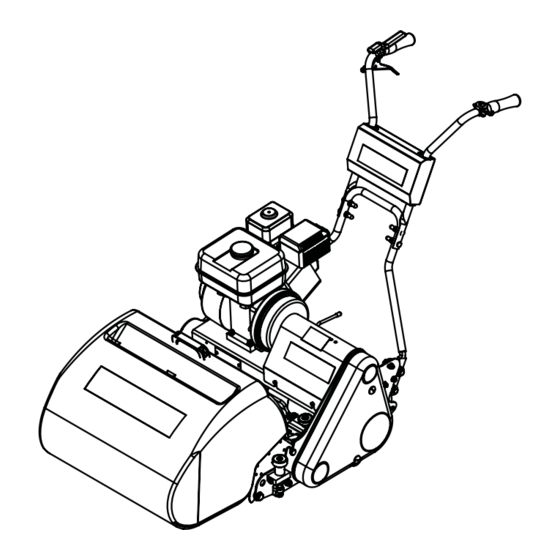
Page 5: Machine Description
Machine Description Manufactured with a 17” (43cm) 20” (51cm) or 24” (61cm) cutting width this mower is powered by a 5.5 h.p. air cooled single cylinder four stroke petrol engine (3.5hp FT430) The rear roller is powered via a slipping brake band clutch mechanism that allows infi... -
Page 6: Important Safety Instructions
TRAINING READ THE INSTRUCTIONS CONTAINED IN THIS MANUAL WITH CARE. IF YOU ARE IN CAUTION ANY DOUBT PLEASE ASK YOUR EMPLOYER OR CONTACT US DIRECT AT DENNIS. • Be familiar with the controls and the proper use of the equipment. -
Page 7: Operating Instructions
Operating Instructions BEFORE YOU OPERATE THIS MACHINE YOU MUST READ AND STUDY THIS MANUAL. CAUTION IF YOU ARE IN ANY DOUBT PLEASE ASK YOUR EMPLOYER OR CONTACT US DIRECT. PREPARATION FOR USE • Before commencing ensure the turf is free from stones or other obstructions which may damage the cassette unit. •... - Page 8 Operating Instructions STARTING THE ENGINE Once the preparatory steps have been completed as outlined on page 7 the engine may be started. (See manufacturer operating manual for full details). 1) Switch on the fuel tap. 2) Switch the handlebar cut off switch to ON, or depress deadmans handle (Item 1) 3) Set the throttle control to a half open position.
-
Page 9: General Adjustments
General Adjustments SETTING FOR HEIGHT OF CUT Always stop the engine before adjusting the height of cut. Failure to do this may result in severe injury. The length of grass after cutting, or depth of scarifi cation / dethatching / brushing, depends on the setting of the front roller in relation to the main frame of the machine. - Page 10 General Adjustments CUTTER SETTING ADJUSTMENT For cutter cylinder cassettes (5 or 9 blade units). For a full view of the setting operation we suggest you remove the cassette from the machine and place on the back fl at edge of the frame at a comfortable height. It is now possible to make adjustments in the machine without cassette removal should you prefer.
- Page 11 General Adjustments HANDLEBAR ADJUSTMENT The height of the Handle Bars can be adjusted to suit various operators. Follow the below instructions:- 1. Remove Bolt (Item 1) on both sides of the machine. 2. Select the require position out of the 3 available. 3.
-
Page 12: Removing The Cassette Unit
Removing The Cassette Unit To remove the cassette unit for maintenance or to exchange cassettes the following procedure should be followed:- 1) Unscrew the hand wheel of the retaining pin for about half-an-inch (13mm) until the pip end is inside the nut on the side frame. 2) Slide the cassette unit along the tie bars as far as it will go until the cutter nut and coupling is clear of the three pins in the driving coupling. -
Page 13: Routine Maintenance
ENGINE The FT is fi tted with a Honda GX160 (GX120 on FT 430) petrol engine. All are single cylinder, overhead valve, 4 stroke, forced air colled engines. For full specifi cations please refer to the manufacturers instruction manual included. -
Page 14: Routine Maintenance
Routine Maintenance BRAKE BAND ADJUSTMENT (Rear Axle Drive) The brake band assembly is mounted on the end of the rear axle spindle on the right hand side of the machine. The assembly comprises a cast iron drum inner member, which is stopped or braked with a lined steel brake band. This operates dry and no lubrication of any kind is required. -
Page 15: General Lubrication
General Lubrication REAR ROLLER The centre section gear case chamber of the rear roller is an assembly in two halves and contains the epicyclic gear system, which runs in an oil bath. The chamber is charged with gear oil EP 90 before the machine leaves the works and should require no further fi lling during the cutting season. -
Page 16: Storage
ENGINE NUMBER. A BOX TO ENTER THESE FOR EASY REFERENCE IS AT THE BEGINNING OF THE MANUAL. This manual contains listing of parts for the Dennis FT430, FT510 and FT610 machines. An illustration of the parts as an assembly is shown above the list. -
Page 17: Guide To Cassette Use
FT Guide to Cassette Use 9 BLADE CYLINDER (SEE PAGE 33) • For cutting fi ne turf areas. • Three bottom blade options. • Comb active or passive. 5 BLADE CYLINDER (SEE PAGE 33) • For general purpose cutting. • Comb active or passive. -
Page 18: Parts Listings
1.01 Chassis - Main Assembly Item No. Part No. Description Quantity Item No. Part No. Description Quantity 229492 Retaining Plate Assy SP02018 Nut 3/8” UNF Nyloc 230004 Support Bracket SP03008 Washer M8 Form A 230006 Support Plate Engine 800104 Cassette Retaining Screw 800020 FT L.H. - Page 19 1.02 Chassis - LH Side Plate Item No. Part No. Description Quantity J209253 Side Plate LH 229741 Buffer Block 229742 Buffer J209072 Chain Case Stud J20216 Unit Limiting Stud J20238 Shoulded Gearing Stud J20008 Back Plate With Hole J20221 Male Coupling J209203 Cassette Driven Pulley / Shaft J209206...
- Page 20 1.03 Chassis - RH Side Plate Item No. Part No. Description Quantity J209254 Side Plate RH J20023 Unit Limiting Stud 229741 Buffer Block 229742 Buffer SP03003 Washer M6 Toothed SP01008 Hex Set Screw M6 x 16 J209229 Clutch Rod Stop J209078 Retaining Screw Plate SP01016...
- Page 21 2.01 Cutter Engagement - Main Assembly Item No. Part Number Description Quantity J209230 Dog Clutch Fork Assy. J179231 17” Clutch Control Rod J209231 20” Clutch Control Rod J249231 24” Clutch Control Rod J20017 Knob - Red J209024 Nut 5/16 BSF Lock (Thin) J209026 Nut 5/16 UNF Lock (Thin) J209019...
- Page 22 3.01 Front Roller - Main Assembly Item No. Part No. Description Quantity 800002 Front Roller Assy 17” 800502 Front Roller Assy 20” 800503 Front Roller Assy 24” J20522 End Block RH J20521 End Block LH 800149 Click Height Adjuster RH 800148 Click Height Adjuster LH 800182...
- Page 23 4.01 Grassbox - Main Assembly Item No. Part No. Description Quantity J179237 FT430 Grassbox Moulding J209237 FT510 Grassbox Moulding J179237 FT610 Grassbox Moulding J209062 Mesh (FT510) J249062 Mesh (FT610) J17257 17” Grassbox Edging Strip J209063 20” Grassbox Edging Strip J249063 24”...
- Page 24 5.01 Guards - Main Assembly Item No. Part No. Description Quantity B32902 Decal Dennis J209074 Brake Band Cover Screw 194946 Chain Case Screw 228031 Belt Guard Seal 1.23m J20712 Belt Guard J20206 Brake Band Cover B32903 Decal Union Jack 228031 Brake Band Seal 0.62m...
- Page 25 229724 Arm Pivot Bush 229725 Pivot Arm Lower Handle 229726 Bush Handle Pivot 229736 Pivot Bolt B32902 Decal Dennis 230035 Handle Lower 17” W.A. 230020 Handle Lower 20” W.A. 230030 Handle Lower 24” W.A. 230040 Handle Upper W.A. Not Shown J20112 Throttle Cable (Honds MKII &...
- Page 26 17 29 7.01 Engine & Drive Kit - Main Assembly Item No. Part No. Description Quantity Item No. Part No. Description Quantity 228103 Coupling Element J209106 E Clip 16mm 230004 Support Bracket 228104 Circlip N1460-0087 See 2.01 Cutter Engagment Assy (FT430) 228105 Circlip D1460-25 See 2.01...
- Page 27 7.02 Engine & Drive Kit - Centrifugal Clutch Item No. Part No. Description Quantity 229900 Engine (Honda GX120) 229901 Engine (Honda GX160) 800027 Flywheel Assembly 800026 Clutch Hub Assembly J209233 Stub Shaft 228102 Coupling Shaft (7/8”) J209025 Key (3/16” x 3/16” x 1 3/4”) J20467 Grub Screw (M8 x 8) J20367...
- Page 28 8.01 Rear Roller - Main Assembly Item No. Description Part Number Quantity See 8.02 Rear Roller Assy J20119 Spring Scraper Brake Band J20256 Roller Slot Cover Plate J20461 Brake Drum J20463 Brake Band Assy J209201 Rear Roller Driven Pulley SP03016 Washer M10 Form C SP02008 Nut M10 Nyloc...
- Page 29 8.02 Rear Roller - Roller Assembly Item No. Description Part Number Quantity See 8.05 RH Differential Assy See 8.04 LH Differential Assy See 8.03 Outer Roller Assy See 8.03 Outer Roller Assy J20477 LH Spacer Collar J20450 LH Bearing Housing J20454 Bearing R18 2RS J20475...
- Page 30 8.03 Rear Roller - Outer Roller Assembly Item No. Part Number Description Quantity J179540 17” LH Outer Roller c/w Bush J179541 17” RH Outer Roller c/w Bush 800019L 20” LH Outer Roller c/w Bush 800019R 20” RH Outer Roller c/w Bush 800044L 24”...
- Page 31 8.04 Rear Roller - LH Differential Assembly Item No. Part No. Description Quantity 800005 Pinion Shaft Assy (FT430) 800014 Pinion Shaft Assy (FT510) 800039 Pinion Shaft Assy (FT610) J20400 Planet Gear Case J17401 17” Pinion Gear Case Tube J20401 20” Pinion Gear Case Tube J24401 24”...
- Page 32 8.05 Rear Roller - RH Differential Assembly Item No. Part No. Description Quantity 800006 17” Annular Gear Shaft Assy 800015 20” Annular Gear Shaft Assy 800040 24” Annular Gear Shaft Assy J20420 Annular Gear Case J17421 17” Annular Gear Case Tube J20421 20”...
- Page 33 9.01 Cassette - Cutter Item No. Part No. Description Quantity Item No. Part No. Description Quantity J19998 Cassette Side Plate W.A. L.H. J209303 Adjuster Rod J19999 Cassette Side Plate W.A. R.H. J209304 Shim Od: 22 Id:16 THK 0.3 J17040 Cylinder 5 Blade 17” J20008 Back Plate With Hole J20040...
- Page 34 * - Multi Brush Shown 9.02 Cassette - Brush Item No. Part No. Description Quantity Item No. Part No. Description Quantity 228062 3/4” Tube Bung (3132) SP01011 Hex Set Screw (3/8” UNF x 3/4”) 800174 Brush Shaft Assembly (17” Multi) SP02004 Nut Nyloc (M6) 800186...
- Page 35 1 & 2mm Std 2mm Tungsten 9.03 Cassette - Scarifi ers Item No. Part No. Description Quantity Item No. Part No. Description Quantity 228062 3/4” Tube Bung (3132) SP01008 Hex Set Screw (M6 x 16) 800047 1mm Scarifi er Hob Assy (17”) SP01009 Hex Set Screw (M8 x 20) 800052...
- Page 36 9.04 Cassette - Slitter Item No. Part No. Description Quantity Item No. Part No. Description Quantity 230318 Blanking Plate J20057 Scarifer Blade 2mm J20000 Cassette Side Plate WA ND J17011 Cassette Tie Bar (17”) Not Shown J20011 Cassette Tie Bar (20”) J20059 Nut 7/8”...
- Page 37 9.05 Cassette - Sorrel Item No. Part No. Description Quantity 228062 3/4” Tube Bung (3132) 230318 Blanking Plate J20000 Cassette Side Plate WA ND J17011 Cassette Tie Bar (17”) J20011 Cassette Tie Bar (20”) J24011 Cassette Tie Bar (24”) J20023 Unit Limiting Stud J20051 Bearing Housing (6204)
- Page 38 Tungsten 9.06 Cassette - Verticutters Item No. Part No. Description Quantity Item No. Part No. Description Quantity 228062 3/4” Tube Bung (3132) SP02016 Nut (1/2” UNF) 800049 Verticutter Hob Assy (17”) SP03004 Washer (M8 Toothed) 800054 Verticutter Hob Assy (20”) SP03005 Washer (M10 Toothed) 800059...
-
Page 39: Notes
Notes FT Range SP20001_REV_2... - Page 40 DENNIS, Ashbourne Road, Kirk Langley, Derby, DE6 4NJ, United Kingdom Telephone:- 01332 824777 Fax:- 01332 824 525 E-mail:- sales@dennisuk.com E-mail:- spares@dennisuk.com www.dennisuk.com...