Table of Contents
Advertisement
This .pdf document is bookmarked
Operating Instructions and Parts Manual
42" x 24" Woodturning Lathe
Model 4224B
WALTER MEIER (Manufacturing) Inc.
427 New Sanford Road
LaVergne, Tennessee 37086
Part No. M-1794224B
Ph.: 800-274-6848
Revision B2 09/2012
www.powermatic.com
Copyright © 2012 Walter Meier (Manufacturing) Inc.
Advertisement
Table of Contents

Related Manuals for Powermatic 4224B


Summary of Contents for Powermatic 4224B
- Page 1 This .pdf document is bookmarked Operating Instructions and Parts Manual 42” x 24” Woodturning Lathe Model 4224B WALTER MEIER (Manufacturing) Inc. 427 New Sanford Road LaVergne, Tennessee 37086 Part No. M-1794224B Ph.: 800-274-6848 Revision B2 09/2012 www.powermatic.com Copyright © 2012 Walter Meier (Manufacturing) Inc.
-
Page 2: Warranty And Service
This warranty covers only the initial purchaser of the product. WHAT IS THE PERIOD OF COVERAGE? The general POWERMATIC warranty lasts for the time period specified in the product literature of each product. WHAT IS NOT COVERED? The Five Year Warranty does not cover products used for commercial, industrial or educational purposes. Products with a Five Year Warranty that are used for commercial, industrial or education purposes revert to a One Year Warranty. -
Page 3: Table Of Contents
13.0 Optional accessories ............................29 14.0 Troubleshooting the 4224B..........................30 15.0 Recommended Lathe Speeds (per diameter of workpiece) ................31 16.0 Belt Positions for 4224B ............................ 31 17.0 Replacement Parts ............................32 17.1.1 Headstock Assembly – Exploded View ....................33 17.1.2 Headstock Assembly –... - Page 4 17.7.2 Tailstock Riser Block Assembly (Optional Accessory) – Parts List ............47 17.8.0 Outboard Turning Stand (Optional Accessory) – Exploded View............48 17.8.1 Outboard Turning Stand (Optional Accessory) – Parts List ..............48 18.0 Electrical Connections – 4224B Lathe ......................49...
-
Page 5: Safety Warnings
10. Do not operate this machine while tired or under the influence of drugs, alcohol or any medication which may impair your judgment. 11. Make certain switch is in OFF position before 3.0 Safety warnings connecting machine to power supply. 12. -
Page 6: About This Manual
4.0 About this manual This manual is provided by Walter Meier (Manufacturing) Inc. covering the safe operation and maintenance procedures for a Powermatic Model 4224B Woodturning Lathe. This manual contains instructions on installation, safety precautions, general operating procedures, maintenance instructions and parts breakdown. -
Page 7: Features
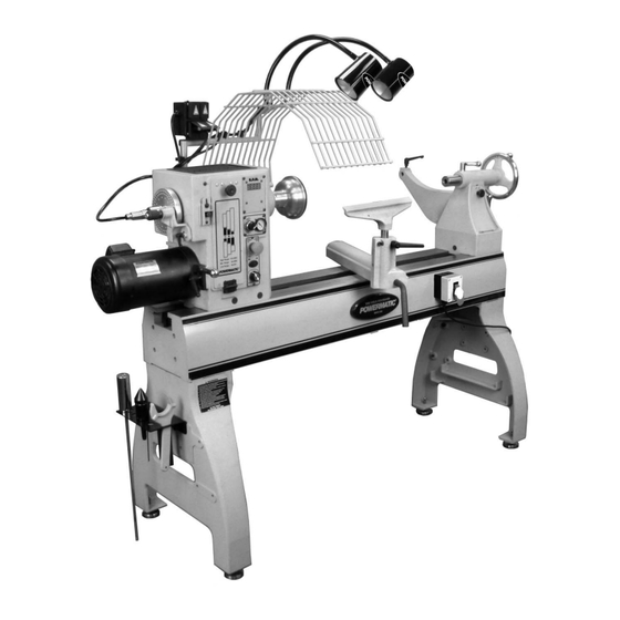
5.0 Features Figure 1 1. Sliding headstock 14. Ledges for shelf support 2. Rubber tool mat 15. Leveling feet 3. Quad receptacle 16. Sturdy cast iron bed with precision ways 4. Guard 17. Front-mounted controls 5. Gooseneck lamps (bulbs not included) 18. -
Page 8: Specifications
6.0 Specifications Model number ................................. 4224B Stock number..............................1794224K Motor and electricals: Motor type ......................totally enclosed fan cooled, induction Horsepower ............................3 HP (2.2 kW) Phase ...................................3 PH Voltage ................................220V Cycle ................................... 60Hz Listed FLA (full load amps)........................... 10 A Starting amps ................................. - Page 9 Dimensions: Leg footprint ......................... 63”L x 24”W (1600 x 610 mm) Bed length ............................63” (1600 mm) Overall height, floor to top of headstock, without levelers .............. 49-1/2” (1257 mm) Distance floor to spindle centerline (adjustable)..................... 44” Overall dimensions, shipping .............. 68”L x 27”W x 31.5”H (1727 x 686 x 800 mm) Overall dimensions, assembled ............
-
Page 10: Setup And Assembly
Comparator spur center ......1 Toolrest Base/Remote switch ....1 Comparator dead center ......1 Vacuum chuck......... 1 Hardware Package (p/n 4224B-HP): Air blow gun with hose......1 HP-1 Socket head cap screw, 3/8x1-1/4 ..2 Vacuum adaptor support bracket ..1 HP-2 Socket head cap screw 3/8x1-1/2 ... -
Page 11: Tools Required For Assembly
14mm open-end or socket wrench (for lamps) sure nothing is beneath that would scratch the bed ways). Turn it opposite direction from Powermatic logo plate to prevent damage to Other tools may be required, depending upon any plate. optional accessories you purchased. -
Page 12: Tool Caddy
7.7 Lamp holder set 8. With assistance, raise bed and leg assembly right-side up. 1. Install shaft of lamp holder (F, Figure 9) into guard bracket hole, and tighten handle (G). Bed and leg assembly is 2. Install collar (H) beneath and tighten set screw heavy. -
Page 13: Air/Vacuum System
4. The guard can be pivoted to one of two The following items are optional and purchased positions: Operating mode, or tilted back for separately. See your Powermatic dealer for stock loading. information. If you did not purchase an optional 5. - Page 14 Figure 16 4. Install elevating system (Figure 17) to bed extension with four 3/8" screws and washers, Figure 14 and to lathe leg with three 1/2” screws and washers (A, Figure 17). Note that top screw is 7. Unscrew stop bolt from lathe bed (Figure 15), installed from inside the leg and secured with and insert it into hole at end of bed extension.
-
Page 15: User-Made Shelf Assembly
IMPORTANT TIP: It is unlikely that a full-size shelf can be completely built and then inserted between the Lathe legs. Therefore, construct the shelf in pieces and insert screws only after the shelf has been established beneath the Lathe. Shelf Style 1 (Figure 20) Lay two 2x6 boards flat upon the inner ledges. -
Page 16: Electrical Connections
This machine must be properly grounded to help prevent electrical shock and possible fatal injury. The 4224B Lathe will operate on single phase or three phase, 230 volt power supply. Make sure the characteristics of your power supply match the power specifications on the lathe inverter. -
Page 17: Extension Cords
The inverter does not require any programming; it has been pre-programmed from the factory. The buttons on the face of the inverter should never be pushed at any time. Use only the controls on the front of the headstock. If you suspect a problem with the inverter or its settings, contact Walter Meier (Manufacturing) Inc., technical service at 1-800-274-6848. -
Page 18: Tool Support
9.3 Tool support now be removed by holding body stationary while unscrewing cone. A 14” tool support is provided with your lathe. It is designed to allow adjustment for height, position on 9.6 Indexer the bed, and angle to the work. The indexer is used to create evenly spaced Loosen locking handle on tool support base (C, features in a workpiece, while keeping the lathe... -
Page 19: Centers: Installing/Removing
9.7 Centers: Installing/removing If at any time you will be reversing spindle rotation, make sure the two 1. Disconnect lathe from power source. set screws in the face plate are tight! Failure to 2. To install a spur center or live center (a spur do this may cause the face plate to loosen from center should first be mounted to your the headstock spindle. -
Page 20: Speed Change
4. There should be sufficient slack in the belt to reposition it to the other steps on the sheaves. The label on the access door shows the required belt position. Figure 29 3. Install comparator dead center comparator bracket and tighten lock handle. See Figure 30. -
Page 21: Sheave And Belt Alignment
NOTE: You may have to tap the end of the spindle with a wood block to move it. (Never use a steel face hammer directly against the spindle.) Figure 32 5. The bearing lock nut should be tightened just enough to remove end play, and spindle should still rotate freely. -
Page 22: Operating Controls
10.0 Operating controls 11.0 Operation See Figures 33 and 34. The information which follows is general in nature and not intended to be a complete course in (H) Vacuum on/off switch with gauge. woodturning. Nothing can replace the knowledge gained by talking with experienced woodturners or (I) On/Off (headstock): Push in to stop lathe;... -
Page 23: Spindle Turning
11.3 Spindle Turning Parting Tool - 1/8", used for scraping, making a cut-off, or to set diameters for sizing. Spindle turning takes place between the centers of the lathe. It requires a spur or drive center in the headstock and a live or dead center in the tailstock. A cup center rather than a cone center in the tailstock will often reduce the risk of splitting the stock. -
Page 24: Cutting Techniques
3. Drive the spur center about 1/4” into the used. Consult digital readout workpiece, using a wood mallet or dead blow headstock. hammer as shown in Figure 38. Be careful that you do not split the workpiece. Never use a steel face hammer and never drive the workpiece onto the spur center while it is mounted in the Lathe spindle. -
Page 25: Face Plate And Bowl Turning
6. Add details to the workpiece with skew, parting tool, scraper or spindle gouge. 11.5.2 Beads 1. Make a parting cut for what is to be a bead to the desired depth. Place the parting tool on the tool support and move tool forward to make the full bevel of the tool come into contact with the workpiece. - Page 26 11.6.1 Mounting Stock 11.6.2 Faceplate or Chuck? Use of a face plate is the most common method for While faceplates are the simplest, most reliable holding a block of wood for turning bowls and method of holding a block of wood for turning, plates: chucks can also be used.
-
Page 27: Bowl Turning Techniques
other gouges. Most average sized bowl work can 10. Finish turning the outside of bowl with 1/2" or be accomplished with a 3/8" or 1/2" bowl gouge. A 3/8" bowl gouge. Leave additional material at 1/4" bowl gouge is best suited for smaller bowls base of bowl for support while turning interior. -
Page 28: Maintenance
Failure to comply may cause serious injury. 7. Develop wall thickness at the rim and maintain Maintenance on the 4224B Lathe should be it as you work deeper into the bowl (Once the performed at periodic intervals to ensure that the... -
Page 29: Optional Accessories
13.0 Optional accessories These items, purchased separately, can enhance the functionality of your lathe. Contact your Powermatic dealer for more information. p/n 6294732 – Heavy duty outboard turning stand p/n 6294905 – 20-inch Bed Extension p/n 6294900 – 20-inch Bed Extension Kit p/n 6294740 –... -
Page 30: Troubleshooting The 4224B
14.0 Troubleshooting the 4224B Trouble Probable Cause Remedy Lathe won’t start. No incoming power. Check power supply, lead connections Remote switch stop is active. Reset remote switch. Contact Walter Meier Technical Problem with inverter. Service. Motor fails to develop Undersized wires in power supply Increase supply wire size. -
Page 31: Recommended Lathe Speeds (Per Diameter Of Workpiece)
1080 1650 6” to 8” 1240 8” to 10” 1000 10” to 12” 12” to 14” 14” to 16” 16” to 20” 20” to 24” Table 3 16.0 Belt Positions for 4224B High: 135-3500 Medium: 80-2000 Low: 40-970 Figure 46... -
Page 32: Replacement Parts
17.0 Replacement Parts Replacement parts are listed on the following pages. To order parts or reach our service department, call 1- 800-274-6848 Monday through Friday (see our website for business hours, www.waltermeier.com). Having the Model Number and Serial Number of your machine available when you call will allow us to serve you quickly and accurately. -
Page 33: Headstock Assembly - Exploded View
17.1.1 Headstock Assembly – Exploded View... -
Page 34: Headstock Assembly - Parts List
5 ....6294725 ....Spur Center............MT2 ......1 6 ....4224B-106 ....Spindle ....................1 7 ....4224B-107 ....Key ..............6 x 6 x 90 mm..... 1 8 ....4224B-108 ....Key ..............6 x 6 x 35 mm..... 1 9 ....BB-6209ZZ ....Ball Bearing............6209ZZ ...... 2 10 .... - Page 35 ....6295760-1 ....Remote Switch Safety Key ..............1 111 ..4224B-1112.....Magnet ....................2 ....4224B-KRA .....Knockout Rod Assembly (includes #113 thru 117) ........ 1 113 ..3520B-288 ....Slide Hammer ..................1 114 ..TS-0267041 ....Set Screw ............1/4"-20 x 3/8” ....2 115 ..
- Page 36 119 ..TS-0206031 ....Socket Head Cap Screw ........#10-24 x 5/8” ....7 120 ..4224B-143 ....Wave Washer..................1 121 ..6294786 ....Spindle Lock Guard ................1 122 ..4224B-1122.....Spindle Lock Tab ................1 123 ..TS-069204 ....Flat Washer............#10 ......1 124 ..4224B-1124.....Warning Label, Faceplate..............1...
-
Page 37: Bed And Leg Assembly - Exploded View
17.2.1 Bed and Leg Assembly – Exploded View... -
Page 38: Bed And Leg Assembly - Parts List
21 .... TS-0253031 ....Socket Head Button Screw ........#10-24 x 1/2” ....2 22 .... 3728005 ....Quill Lock Sleeve ................1 ....4224B-LBA ....Lock Bolt Assembly (includes #23 and 25)..........1 23 .... 4224B-223 ....Lock Bolt .................... 1 24 .... TS-0209061 ....Socket Head Cap Screw ........3/8”-16 x 1-1/4” ... 1 25 .... - Page 39 Description Size Q’ty 58 .... 4224B-258 ....Socket Head Cap Screw ........1/2”-12 x 1”....2 59 .... TS-0680041 ....Flat Washer............3/8” ......11 60 .... TS-0720091 ....Lock Washer ............3/8” ......10 61 .... TS-0209071 ....Socket Head Cap Screw ........3/8”-16 x 1-1/2” ... 8 62 ....
-
Page 40: Lamp Holder Set - Exploded View
17.3.1 Lamp Holder Set – Exploded View... -
Page 41: Lamp Holder Set - Parts List
42 .... * ......Stud ..............M51 ......2 43 .... * ......Lock Washer, Internal tooth .......3/8” ......2 44 .... * ......Jam Nut ............3/8” ......2 NOTE: Powermatic lamps are supplied by Moffatt. For replacement parts indicated by an asterisk (*), contact Moffatt directly at 800-346-0761. -
Page 42: Vacuum System - Exploded View
17.4.1 Vacuum System – Exploded View... -
Page 43: Vacuum System - Parts List
25 .... 4224B-425 ....Union ....................1 26 .... 4224B-426 ....Elbow Fitting.............1/4” NPT ....3 ....4224B-BGS .....Air Blow Gun Set (includes #27 thru 28) ..........1 27 .... 4224B-427 ....Air Line ............3M ......1 28 .... 4224B-428 ....Air Blow Gun ..................1 29 .... -
Page 44: 20-Inch Extension Bed Kit (Optional Accessory) - Exploded View
17.5.1 20-inch Extension Bed Kit (Optional Accessory) – Exploded View... -
Page 45: 20-Inch Extension Bed Kit (Optional Accessory) - Parts List
....6294900 ....20” Extension Bed Kit (includes #1 thru 27) .......... 1 1 ....6294905 ....20” Extension Bed with mounting hardware .......... 1 2 ....4224B-502 ....Socket Head Cap Screw ........1/2”-12x2” ....7 3 ....TS-0720111 ....Lock Washer ............1/2” ......6 4 .... -
Page 46: 63-Inch Extension Bed Assembly (Optional Accessory) - Exploded View
....6294904 ....63” Extension Bed with Leg (includes #1 thru 10 .) ........ 1 1 ....4224B-201 ....Bed....................1 2 ....4224B-202 ....Leg ....................1 3 ....4224B-502 ....Socket Head Cap Screw ........1/2”-12x2” ....4 4 ....TS-0720111 ....Lock Washer ............1/2” ......4 5 ....TS-0680061 ....Flat Washer............1/2” ......4 6 .... -
Page 47: Tailstock Riser Block Assembly (Optional Accessory) - Exploded View
Size ....6294903 ....Tailstock Riser Block Assembly (includes #1 thru 16) ......1 ....6295754 ....Stop Bolt .................... 1 2 ....4224B-602 ....Riser Block Casting ................1 3 ....4224B-165 ....Lock Handle ..................1 4 ....4224B-229 ....Rod ....................1 5 .... -
Page 48: Outboard Turning Stand (Optional Accessory) - Exploded View
17.8.0 Outboard Turning Stand (Optional Accessory) – Exploded View 17.8.1 Outboard Turning Stand (Optional Accessory) – Parts List Index No. Part No. Description Size Qty....6294732 ....Heavy Duty Outboard Turning Stand Assembly (includes # 1 thru 7) ..1 ....3042503 ....Turning Stand Base ................1 2 .... -
Page 49: Electrical Connections - 4224B Lathe
18.0 Electrical Connections – 4224B Lathe... - Page 50 NOTES...
- Page 51 NOTES...
- Page 52 WALTER MEIER (Manufacturing) Inc. 427 New Sanford Road LaVergne, Tennessee 37086 Phone: 800-274-6848 www.powermatic.com www.waltermeier.com...
Need help?
Do you have a question about the 4224B and is the answer not in the manual?
Questions and answers